Arduinos and Microcontrollers ref: Rotary Table Mew 249

Advert

Arduinos and Microcontrollers ref: Rotary Table Mew 249

Home Forums Electronics in the Workshop Arduinos and Microcontrollers ref: Rotary Table Mew 249

Viewing 18 posts - 226 through 243 (of 243 total)
  • Author
    Posts
  • #551792
    John Haine
    Participant
      @johnhaine32865

      If you have some small nut driver sockets a simple tip to make spacers is to mount one in the lathe chuck, feed a small stack of appropriate sizes nuts into the hex hole, bring a nominal clearance drill for the thread size in the t/s so so it nearly touches the first nut, start the lathe and feed slowly. As each nut is drilled out it slides onto the drill as you go into the next. Use nylon nuts for plastic spacers.

      Advert
      #551797
      Greensands
      Participant
        @greensands

        Journeyman – I have sent you a PM

        #551802
        Journeyman
        Participant
          @journeyman

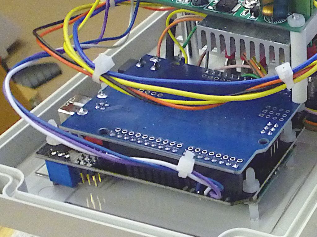
          Greensands, replied to PM. This image might help.

          unomount.jpg

          John

          #573536
          Tony Pratt 1
          Participant
            @tonypratt1
            Posted by SillyOldDuffer on 09/12/2016 20:07:18:

            Posted by Engine Builder on 09/12/2016 19:39:26:

            sillyoldduffer,

            I manged to alter the sketch to verify the key voltages and got similar results to your one.

            If it helps other builders my LCD shield is badged DF ROBOT (Drive the Future)

            This is the results I got.

            • NO_KEY 1023
            • RIGHT_KEY 0
            • UP_KEY 98
            • DOWN_KEY 253
            • LEFT_KEY 408
            • SELECT_KEY 639

            Good work, you're officially a computer hacker now!

            My LCD is a DF Robot as well – perhaps they all produce voltages like that.

            I haven't got any further than getting the arduino and display to work. I wrongly thought I had a suitable motor, lack of which has taken the wind out of my sales…

            Cheers,

            Dave

            Hi All, I'm now having a go at this project but have failed at the first hurdle, my figures are NO KEY 1022, SELECT 6412, LEFT 4112, RIGHT 0022, UP 1002, DOWN 2572, these seem way too high?? any ideas? Thanks, Tony

            #573544
            SillyOldDuffer
            Moderator
              @sillyoldduffer
              Posted by Tony Pratt 1 on 29/11/2021 19:43:05:

              Posted by SillyOldDuffer on 09/12/2016 20:07:18:

              Posted by Engine Builder on 09/12/2016 19:39:26:

              sillyoldduffer,

              I manged to alter the sketch to verify the key voltages and got similar results to your one.

              If it helps other builders my LCD shield is badged DF ROBOT (Drive the Future)

              This is the results I got.

              • NO_KEY 1023
              • RIGHT_KEY 0
              • UP_KEY 98
              • DOWN_KEY 253
              • LEFT_KEY 408
              • SELECT_KEY 639

              Good work, you're officially a computer hacker now!

              My LCD is a DF Robot as well – perhaps they all produce voltages like that.

              I haven't got any further than getting the arduino and display to work. I wrongly thought I had a suitable motor, lack of which has taken the wind out of my sales…

              Cheers,

              Dave

              Hi All, I'm now having a go at this project but have failed at the first hurdle, my figures are NO KEY 1022, SELECT 6412, LEFT 4112, RIGHT 0022, UP 1002, DOWN 2572, these seem way too high?? any ideas? Thanks, Tony

              That's strange Tony. The buttons short out a line of resistors (circuit here, see lower right), and the values can only be between 0 and 1024. Your 1022 and 0022 look right but the other readings are off the scale. What hardware are you using?

              Dave

              #573555
              Tony Pratt 1
              Participant
                @tonypratt1

                Hi Dave, thanks for the swift reply! The board is a Sunfounder model Uno R3, the shield has no name that I can see? I have ordered a new board & shield from Amazon to see if the figures make any sense with them, if no go is there any particular brand that is reliable, as most seem to be made in China generics?

                Thanks Tony

                #573616
                An Other
                Participant
                  @another21905

                  Arduino Unos have an analog input resolution og 10 bits, so the value read will be between 0 to 1023. Some Arduino board types have 12 bit resolution, so the value read will be between 0 and 4095. It is possible there are some 3rd party boards with 12 bit resolution (I have at least 2 of these)

                  As noted, the shield has a resistor chain connected between 0 and +5v, and the pushbuttons are connected across these resistors,so when you press one, the value of the chain changes, therefore the voltage at the Arduino analog input is changed, and the Arduino reads this as a value between 0 and 1023 (see above) – note that this switching is on the shield, not the Arduino.

                  The values read are not 'absolute' – they can vary slightly, and will not be the same from one board to another, due to things like resistor tolerance, so when testing for a value, you should check they lie between an upper and lower value (say a range of +/- 5 or 10).

                  It would appear to me that the odd values noted by Tony may be due to a programming error. There are many shields carrying LCDs/buttons – they all have different resistor chains, so although a 'testing' program could have the same format, the values read will be different.

                  #573618
                  An Other
                  Participant
                    @another21905

                    Duplicate post removed.

                    Edited By An Other on 30/11/2021 10:20:37

                    #573622
                    An Other
                    Participant
                      @another21905

                      If its any use- below is my test code for these LCD/Button Shields.

                      .

                      #include <LiquidCrystal.h>

                      //LCD pin to Arduino
                      const int pin_RS = 8;
                      const int pin_EN = 9;
                      const int pin_d4 = 4;
                      const int pin_d5 = 5;
                      const int pin_d6 = 6;
                      const int pin_d7 = 7;

                      const int pin_BL = 10;

                      LiquidCrystal lcd( pin_RS, pin_EN, pin_d4, pin_d5, pin_d6, pin_d7);

                      void setup() {

                      lcd.begin(16, 2);

                      lcd.setCursor(0,0);

                      lcd.print("LCD Key Shield&quot;
                      lcd.setCursor(0,1);
                      lcd.print("Press Key:&quot;
                      }

                      void loop() {
                      int x;
                      x = analogRead (0);
                      lcd.setCursor(10,1);

                      //The values given below may need changing depending on the LCD/Button shield
                      if (x < 60) {
                      lcd.print ("Right &quot;
                      }
                      else if (x < 200) {
                      lcd.print ("Up &quot;
                      }
                      else if (x < 400){
                      lcd.print ("Down &quot;
                      }
                      else if (x < 600){
                      lcd.print ("Left &quot;
                      }
                      else if (x < 800){
                      lcd.print ("Select&quot;
                      }
                      } /End

                      #573624
                      Michael Gilligan
                      Participant
                        @michaelgilligan61133

                        Don’t you just hate those smileys angry

                        MichaelG.

                        #573630
                        An Other
                        Participant
                          @another21905

                          Thats really annoying – they weren't there when I posted. I left the site, came back later to check something else, and found this – worse than graffiti. If anyone is confused,it seems that the smileys replace the right-hand round bracket – they aren't part of the code laugh – and that smiley was deliberate!

                          Something else odd – when I opened the thread, the line at the top indicated there were 12 pages (7 89 10 11 12), but after posting, this changed to 10 pages (7 8 9 10) – are there some pages missing?, or is it just this lousy software.

                          Edited By An Other on 30/11/2021 11:08:42

                          #573632
                          Tony Pratt 1
                          Participant
                            @tonypratt1

                            Thanks guys, comments noted.

                            Tony

                            #573641
                            Peter Cook 6
                            Participant
                              @petercook6

                              While this thread is resurrected, I thought I might point people at the prototyping sheilds I found when making my lathe controller. They are from Electronics – W19 Design, and have by far the nicest layout I have come across.

                              Rather than being an array of through holes, there is an array of 3 or 4 hole tracks and some longer ( power rails) which makes making connections between components and the Arduino pins far simpler and neater.

                              I have no connection other than a very happy user.

                              #573643
                              Michael Gilligan
                              Participant
                                @michaelgilligan61133
                                Posted by Peter Cook 6 on 30/11/2021 12:38:27:

                                While this thread is resurrected, I thought I might point people at the prototyping sheilds I found when making my lathe controller. […]

                                .

                                Those do look very tidy, Peter yes

                                But, am I right in assuming that the company has no association with Vero

                                [ purveyors of strip-boards to the gentry ] ?

                                MichaelG.

                                .

                                Ref. http://verotl.com/circuitboards/protoboards

                                Edited By Michael Gilligan on 30/11/2021 12:58:30

                                #573658
                                Peter Cook 6
                                Participant
                                  @petercook6

                                  Michael, Not that I know of – I'm just a customer. They seem to be a firm that makes custom exhibition stands, and this is something they designed to make construction of Arduino based specials easier.

                                  Personally I'm glad they put them on the market – the short tracks make laying out and building one-off's far easier than the usual shields – although it would be interesting to know if they have permission from Vero for the name!!

                                  Edited By Peter Cook 6 on 30/11/2021 14:19:38

                                  #573670
                                  Michael Gilligan
                                  Participant
                                    @michaelgilligan61133
                                    Posted by Peter Cook 6 on 30/11/2021 14:17:11:

                                    […]

                                    – although it would be interesting to know if they have permission from Vero for the name!!

                                    .

                                    Thanks, Peter … Yes that was my point

                                    They do look very useful though yes

                                    MichaelG.

                                    #573677
                                    SillyOldDuffer
                                    Moderator
                                      @sillyoldduffer
                                      Posted by Tony Pratt 1 on 29/11/2021 21:34:52:

                                      Hi Dave, thanks for the swift reply! The board is a Sunfounder model Uno R3, the shield has no name that I can see? I have ordered a new board & shield from Amazon to see if the figures make any sense with them, if no go is there any particular brand that is reliable, as most seem to be made in China generics?

                                      Thanks Tony

                                      Yes, you might have a duff Uno or Shield. Values higher than 1023 suggest a hardware failure. My LCD Shield came from DF-Robot, and I've used Sunfounder several times without bother, but the breed do turn up poorly sometimes. I try to avoid the very cheap no-brand boards, but the few I've used have been OK (I think I've only had two failures in over 100 purchases.)

                                      You might try this test program, which can be used to test the Uno because it doesn't need the LCD shield plugged in. Instead it reports to the IDE's Serial Monitor at 9600baud.

                                      Compile and load it onto the bare Uno, then turn the serial monitor on and set the baud rate to 9600 baud.

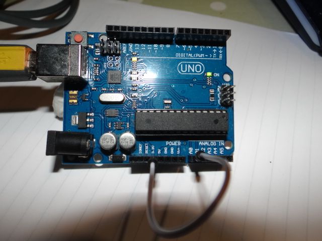
                                      With nothing plugged into pin A0 should display a random value between 0 and 1023 due to picking up mains hum. Connect a jumper wire from A0 to the 3.3V socket:

                                      dsc06555.jpg

                                      Mine read 647 which equates to 3.16V (Maths: v= 647/1023 * 5V)

                                      Reconnecting the jumper from A0 to a Gnd socket should read 0

                                      And connecting the jumper from A0 to the 5V socket should read 1023

                                      DO NOT connect the jumper from A0 to Vin!!! It will probably fry the ADC function,

                                      This proves the UNO is Ok.

                                      Next plug the shield in. The display won't work, but pressing the buttons down for a few seconds should show the ADC level each causes.

                                      Fingers crossed, both work.

                                      I can't think of a reason why A0 should ever read more than 1023. Possibly the ADC circuit behind A0 is has been spiked. They're robust unless fed more than whatever is on the supply rail, which is 5.0V. I've never killed one, but static might do it.

                                      Dave

                                      #573781
                                      John Olsen
                                      Participant
                                        @johnolsen79199

                                        I've just been playing with an Arduino myself lately so found some of the above quite interesting.

                                        A few points about speed and stepper motors. They can go quite fast, but sometimes need a few tricks. One is that in order to build up the current and hence the magnetic field quite quickly, the drive voltage can be increased. To avoid overcooking things when the motor is running slow or holding, this is done with either a constant current drive or more simply, a resistor in series. The high initial supply voltage gives a faster rise to the current, but the constant current part ensures that the current never exceeds what the winding is rated for.

                                        Then there is the acceleration thing. Depending on the rotational inertia of the whole drive train, if you just start switching at a high speed, the rotor can lose lock. So the controller needs to be set up to accelerate at a reasonable rate, and similarly to decelerate at a reasonable rate. This requires that the controller knows in advance when it is going to be asked to stop the load, so is not so good for unplanned emergency stops. Really if high speeds and sudden changes are needed, a servo motor become a better solution.

                                        I've just implemented some code from the web to allow using the Arduino to remotely display the output from the usual common digital calipers. The original code only did millimeters, so I have messed around a bit and after a few changes have got it to read out correctly for either millimeters or inches, including reading the fourth decimal place correctly. I might get around to doing a DRO for the Myford yet…

                                        John

                                      Viewing 18 posts - 226 through 243 (of 243 total)
                                      • Please log in to reply to this topic. Registering is free and easy using the links on the menu at the top of this page.

                                      Advert

                                      Latest Replies

                                      Viewing 25 topics - 1 through 25 (of 25 total)
                                      Viewing 25 topics - 1 through 25 (of 25 total)

                                      View full reply list.

                                      Advert

                                      Newsletter Sign-up