Arduino Rotary Table MEW 249

Advert

Arduino Rotary Table MEW 249

Home Forums Drawing Errors and Corrections Arduino Rotary Table MEW 249

Viewing 9 posts - 101 through 109 (of 109 total)
  • Author
    Posts
  • #287821
    SillyOldDuffer
    Moderator
      @sillyoldduffer

      There's a new version of my keypad controlled indexer available here.

      The main changes are:

      * v0.6 beta added extra ratios ( Thanks to John Stevenson)

      * v0.7 beta changed keypad to use Pin 11 rather than 13. (Fixes a keypad issue due to pin 13 being 'special' )

      WARNING!

      WIRING CHANGE: Motor PULSE (aka STEP) is now output on Pin 13 not PIn 11 as before. The motor will not turn unless this hardware change is made.  Also Pin 11 replaces Pin 13 on the keypad.  The circuit diagram is not updated yet.

      * v0.8 beta Adds Key repeat. (May be repeating too quickly!)

      * v0.9 beta Allows numbers to be got from keypad by entering # in the JOG, ANGLE & STEP modes. A second # finishes entry . It is now possible to type in a JOG, STEP or ANGLE rather than using +/- to change the number. (Thanks to Duncan Webster)

      Dave

      Edited By SillyOldDuffer on 08/03/2017 19:26:26

      Advert
      #288027
      SillyOldDuffer
      Moderator
        @sillyoldduffer

        Another update here.

        Now that numbers can be changed from the keypad, using + and – keys to increment parameters has been abandoned. It is now possible to change the table gear ratio to any N:1 value.

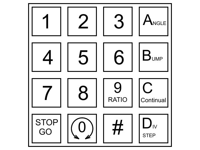
        The keypad layout has been changed to better match a standard 4×4 matrix type. It is laid out like this:

        rt_keypad.jpg

        The right hand ABCD and 9 keys set the operating mode. The table can be turned through an angle, Bumped (jogged), run Continuously, and Division Stepped. Key 9 allows the Ratio to be set.

        The # key allows a number to be typed in, for example the number of degrees to be turned in Angle Mode. Motor speed, Division Step, Bump distance (aka Jog) and Ratio may be controlled in the same way.

        Motor direction is toggled between clockwise and anticlockwise by pressing the 0 key. (This works unless the keypad is entering numbers.)

        The motor is toggled on and off by pressing the * key (marked STOP GO on the diagram).

        The function that allows the Indexer to be controlled by a USB connected PC is still to be tested. I am looking at an I2C display version, but apart from that the project is nearly complete. Unless you know different!

        Dave

        #290992
        john hill 1
        Participant
          @johnhill1

          Hi all,

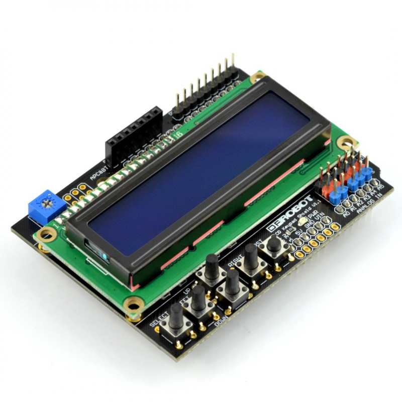
          Thanks for your postings I was able to get my arduino controller to work as I had a DFRobot LCD shield . Changing the numbers to Andrew Holdaway's figures it is working.

          John Australia

          #607202
          Peter Cook 6
          Participant
            @petercook6

            Can I just resurrect this thread to say a big thank you to Dave (SOD) for both the Arduino code and the motor mount design – seen in a different thread.

            I built the mount for my little table, and after wiring up the electronics it all works fantastically well. I only need to mount the electronic components in a box, and I am in business.

            Thanks again for making this available.

            #607218
            john fletcher 1
            Participant
              @johnfletcher1

              I would like to thank Carl Wilson for the help he gave me when making a controller. I went a bit a stray but got there in the end. Three of my friend were so impressed when I cut some gears for my Myford lathe, no counting of holes or thin teeth, they convinced me to do the electronic wiring bits for them. So four down and one more to go. John

              #607333
              SillyOldDuffer
              Moderator
                @sillyoldduffer
                Posted by Peter Cook 6 on 24/07/2022 18:08:54:

                Can I just resurrect this thread to say a big thank you to Dave (SOD) for both the Arduino code and the motor mount design – seen in a different thread.

                I built the mount for my little table, and after wiring up the electronics it all works fantastically well. I only need to mount the electronic components in a box, and I am in business.

                Thanks again for making this available.

                Glad to hear it works Peter! Always a worry that a bug will escape and cause chaos. Not so far, touch wood.

                The late great John Stevenson deserves credit for the idea. He mentioned in connection with the other Arduino table drivers about that he didn't like push-buttons and nested menus, which are unavoidable if the 5 button DF Robot keypad module is used.

                Having 16 keys on a 4 by 4 keypad allows the user interface to avoid nests and numbers can be typed straight in.

                As far as I know, no-one has used the feature I was most proud of, not even me. Complex sequences can be pre-programmed and sent from a PC to the rotary table via the Arduino rather than entered manually with the keypad – a basic Numeric Control capability that might be useful for making cams or such. In practice I've not found an actual practical use for it though. So much for fancy bells and whistles, ho, ho!

                Dave

                #607347
                Peter Cook 6
                Participant
                  @petercook6

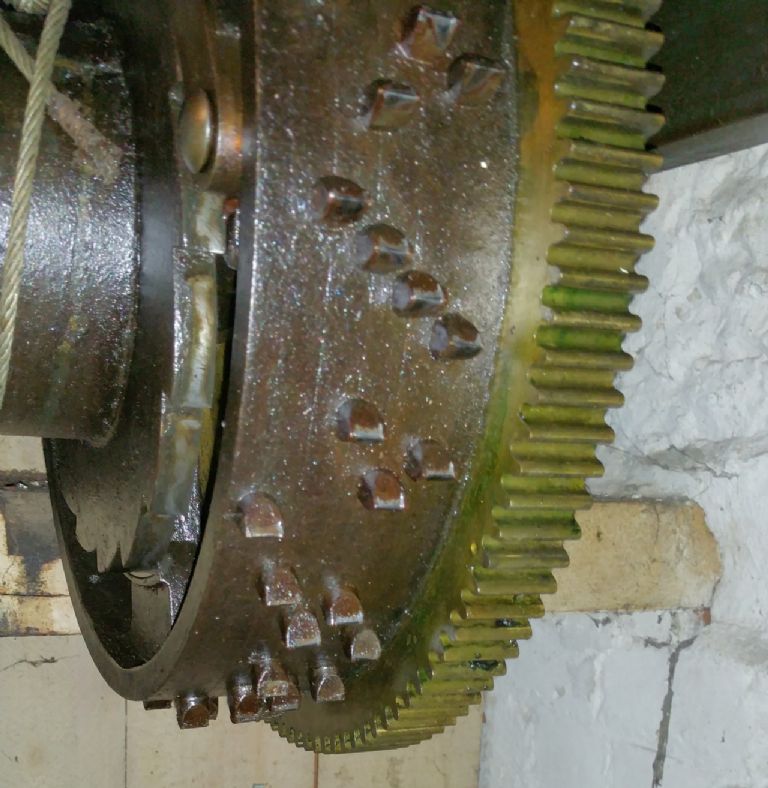
                  Ah, but I do have plans for that function – if they ever come to fulfilment I will let you know. As part of my clock project ( and the table controller is on the plan to help with gear cutting), I will need to make the chime barrel.

                  chime barrel original.jpg

                  It has five tracks with 16 pins per track. The angular spacing of the pins create the sequence of notes for the tune.

                  I am thinking of setting up the barre on the rotary table, and creating a spreadsheet of the angular positions based on the tune. Export that as a sequence of angle commands one for each track and use the commands to drill the necessary holes.

                  PS I made a small change to the code. I have set the default table ratio to 72 to suit my table, and added a default value for  backlashSteps to avoid setting it up every time I switch on.

                  Edited By Peter Cook 6 on 25/07/2022 19:14:56

                  #607357
                  SillyOldDuffer
                  Moderator
                    @sillyoldduffer
                    Posted by Peter Cook 6 on 25/07/2022 19:10:31:

                    Ah, but I do have plans for that function … As part of my clock project …I will need to make the chime barrel.

                    chime barrel original.jpg

                    It has five tracks with 16 pins per track. The angular spacing of the pins create the sequence of notes for the tune.

                    PS I made a small change to the code. I have set the default table ratio to 72 to suit my table, and added a default value for backlashSteps to avoid setting it up every time I switch on.

                    Chime barrel – fiendishly clever, I'd never have thought of that! I wonder how difficult it would be to program a converter to calculate angle and pin positions from a musical score? It would make it easy for a clock designer to provide barrel plans so builders could choose from a large number of different chimes.

                    Default for backlashSteps – good idea. Now why didn't I think of it? Doh!

                    Dave


                    Edited By SillyOldDuffer on 25/07/2022 21:35:22

                    #608579
                    Peter Cook 6
                    Participant
                      @petercook6

                      A final input if anyone stumbles over this thread when planning to build one.

                      I cased the electronics for mine in a nice ABS box, and used it for the first time in anger the other day. It worked like a charm. Taking multiple cuts to mill curved slots in brass was soooo simple.

                      However It all got fiendishly hot. The motor got fairly warm, but no-one has mentioned how hot the stepper controller can get – especially in a closed box. The two bolts holding the stepper driver to the side of the box got so hot I almost burned my fingers.

                      This was my first experience of a stepper motor – the brushless motor on the lathe has a controller with exactly the same chassis and heat sink – but it never gets beyond vaguely warm. I suppose I should have realised. 12v in and only about 2V out with 2.8 amps holding current says that the driver is dissipating about 28 watts

                      Fortunately there was enough room in the box for a 40mm 12v fan ( the system runs on 12v) from the bits box, so some hole making and fettling provided a cooling flow. Things are much better now!

                      But now I know – stepper drivers get hot!

                    Viewing 9 posts - 101 through 109 (of 109 total)
                    • Please log in to reply to this topic. Registering is free and easy using the links on the menu at the top of this page.

                    Advert

                    Latest Replies

                    Viewing 25 topics - 1 through 25 (of 25 total)
                    Viewing 25 topics - 1 through 25 (of 25 total)

                    View full reply list.

                    Advert

                    Newsletter Sign-up