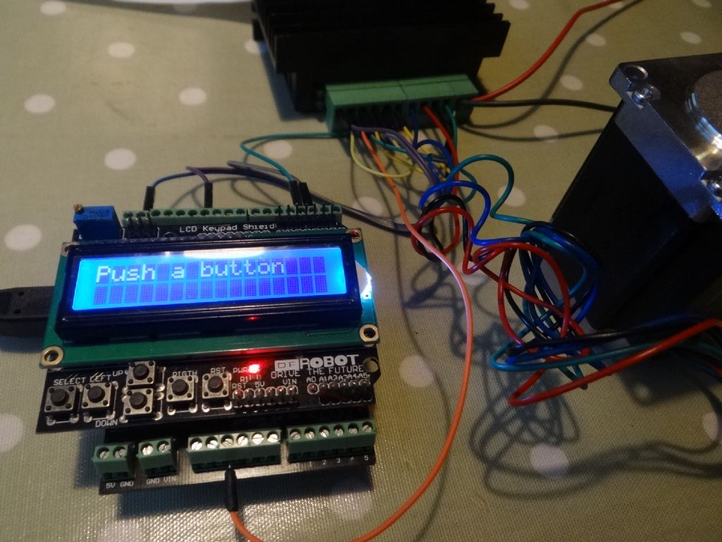
Hello thank you everybody for your invaluable help i have just got both arduinos and the keypads to work after putting so many numbers to get the right hand key to work i arrived at
850 return no key
85 return right key
230 return up key
35o return down key
450 return left key
850 return select key.
The only problem now is even with a 24volt supply it only revolves at about 14rpm as i had hoped to drive a small mill head up and down with one of them with a 3 to 1 reduction Thanks again Graham
Have you changed the sketch to disable microstepping? At the top of the sketch you will see this line
#define Microsteps 1 // Depending on your stepper driver, it may support
// microstepping. Set this number to the number of microsteps
// that is set on the driver board. For large ratios, you may want to
// use no microstepping and set this to 1.
The figure after #define Microsteps should be 1 to give the fastest speed.
Hi. I have built my indexer but I am getting weird results. Everything runs,the arduino is able to select all modes, all the keys do as they should but the stepper motor ( nema 23 ) runs very slowly and I am getting 72000 steps per rev, with ratio set 9 to 1. According to MEW article I should be getting 18000 steps per rev. Where have I gone wrong? I am using Gary Liming’s code ver 2.3. Any help would be well recieved….
#define StepsPerRevolution 200 // Change this to represent the number of steps
// it takes the motor to do one full revolution
// 200 is the result of a 1.8 degree per step motor
#define Microsteps 8 // Depending on your stepper driver, it may support
// microstepping. Set this number to the number of microsteps
// that is set on the driver board. For large ratios, you may want to
// use no microstepping and set this to 1.
Make sure that the motor you are using is 200 steps per revolution, and set Microsteps tp 1.
Also make sure that the DIP switches on the TB6560 are not set for microstepping.
Many thanks, I will have to get a magnifying glass as I cannot see the dip switch chart printed on the board. Stepper motor did not seem to work at first, but after copying switch positions from article I got where I am now. I couldn’t make out the positions of the three black switches so made a guess…
Hello all, thanks to Carl and others on here, Im happy with the way my Arduino RT project has finished up. One strange thing I noticed when using it recently is the way the CW and CCW buttons work in the RUN mode.When using divisions , angles or jog, the left (CW) button turns the table clockwise, and the right (CCW) anti clockwise as it should. However, in the RUN mode, the FIRST press of the left button turns the table anti clockwise, so does the other button. But if I press the left button again, it turns the table clockwise as its supposed to, and then normal after that.!!! This happens every time I select the RUN mode, then corrects itself.
Posted by Roger Williams 2 on 09/02/2017 10:06:43:
Hello all, thanks to Carl and others on here, Im happy with the way my Arduino RT project has finished up. One strange thing I noticed when using it recently is the way the CW and CCW buttons work in the RUN mode.When using divisions , angles or jog, the left (CW) button turns the table clockwise, and the right (CCW) anti clockwise as it should. However, in the RUN mode, the FIRST press of the left button turns the table anti clockwise, so does the other button. But if I press the left button again, it turns the table clockwise as its supposed to, and then normal after that.!!! This happens every time I select the RUN mode, then corrects itself.
Anyone else had this problem ?. Many thanks.
This sounds like the software is losing track (unlikely), resetting the stepper driver or switching between microstep and normal modes.
I think I have cracked it! Altered microstepping to 1 ans put both microstepping dip switches to off. Set ratio to 90 to 1 and set 1 step. Display reported 18000 steps/div, which corresponds to magazine article. I will no doubt find out for cure once motor is grafted on to rotary table. Many thanks Andrew….
i thought you might like to see my offering of my dividing head based on the chuck felllows deign with the software from the one in model engineer workshop
Hi thanks to the help from forum members i got my dfrobot keypad to work running a r/t but i then bought a sainsmart one for another project and in the house in the warm it seems to work ok but take it down to the cold workshop and make it work hard driving a small Emco milling head up an down in the run mode and it does what Roger Williams 2 does.Graham
Now that all seems to be working correctly I am a little confused. When I program in a number of steps, say 4 whenratio is set to 9 :1, the shaft spins a number of times to arrive at division 1. When the button is pressed for division 2, again, the shaft spins a number of times before stopping, but, not at 90 degrees to where division 1 was. I was expecting the shaft to spin as it does, but was expecting it to land 90 degrees on. I am hoping this is due to the ratio and will come right once grafted on to rotary table. I am going to add a 1:1 ratio as a test, as every division should then be equal.
Posted by Nick Clarke 2 on 11/02/2017 17:07:31:
Now that all seems to be working correctly I am a little confused. When I program in a number of steps, say 4 whenratio is set to 9 :1, the shaft spins a number of times to arrive at division 1. When the button is pressed for division 2, again, the shaft spins a number of times before stopping, but, not at 90 degrees to where division 1 was. I was expecting the shaft to spin as it does, but was expecting it to land 90 degrees on. I am hoping this is due to the ratio and will come right once grafted on to rotary table. I am going to add a 1:1 ratio as a test, as every division should then be equal.
If you have a 36:1 ratio table then four divisions = 36/4 = 9 full turns per division
Well I grafted the stepper on to my Sorba rotary table and was most disapointed. Table turns painfully slowly. When I go for 4 divisions the table only moves a tiny portion og the required division, and 45 degrees moves 10 degrees. See video https://youtu.be/yrPmzaC1mMo
Hi thanks to the help from forum members i got my dfrobot keypad to work running a r/t but i then bought a sainsmart one for another project and in the house in the warm it seems to work ok but take it down to the cold workshop and make it work hard driving a small Emco milling head up an down in the run mode and it does what Roger Williams 2 does.Graham
Graham,
This sounds as if your key values aren't quite right.
The Arduino works out which key is pressed by measuring a voltage. The voltage varies: not only with the make and version of the board, but also with the tolerances of the resistors used. If the voltage measured is near a boundary, you may get inconsistent results.
Gary Limings wrote this helpful comment in his code:
// average values for my board were: 0, 144, 324, 505, 742
// add approx 100 to those values to set range
But he didn't explain how to measure those 'average values'.
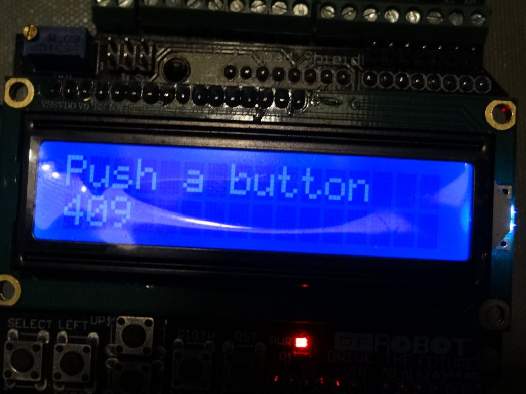
I've knocked up this short program to do just that. It should be compiled and loaded into the Arduino just to find out what your key values actually are. It can be done with the motor connected; the program doesn't use any of the pins.
Once the key values are known, Gary's program can be modified to match your LCD board and reloaded.
In use, the program displays "Push a Button"
After a key has been pressed, it's actual measurement will be displayed for 1.5 seconds. Write the results down for each key (apart from RST!).
From my DFRobot I got: RIGHT 0, UP 100, DOWN 255, LEFT 409 and SELECT 638.
Open Gary's program in the Arduino IDE and scroll to the very end. The last few lines of his code look something like this:
if (key_in > 850) return NO_KEY;
if (key_in < 70) return RIGHT_KEY;
if (key_in < 230) return UP_KEY;
if (key_in < 350) return DOWN_KEY;
if (key_in < 450) return LEFT_KEY;
if (key_in < 850) return SELECT_KEY;
It's the numbers that need to be right. Using Gary's 'add 100 rule' and the measured numbers, the code should be amended to read.
if (key_in > 738) return NO_KEY;
if (key_in < 100) return RIGHT_KEY;
if (key_in < 200) return UP_KEY;
if (key_in < 355) return DOWN_KEY;
if (key_in < 509) return LEFT_KEY;
if (key_in < 738) return SELECT_KEY;
Hello all, just done Silly Old Duffer's LCD Push Button sketch, added 100 to the figures as per Gary Liming, but still the same glitch,….Run mode CW direction goes wrong way on the initial Left button press, then corrects itself after that. . Step, Angle and Jog are perfect !. Must be doing something wrong somewhere.
One thing I have done when re-programming the Arduino, was to make a hole in the box to connect up the USB cable , so much easier than disturbing everything.