Latest report, I've not been idle. Mk2 upgrade now operational and been the target of much experimentation. Physically the clock has a new electromagnet holder, with the magnet fixed to one side and the wiring has been routed to allow the shield to be mounted, but not evacuated yet.

Software upgrades include a general tidy-up, auto start, determination of amplitude and a primitive amplitude regulator.
Experimentation focussed on when best to trigger the impulse. The idea was to minimise the amount of disturbance by minimally pulsing the magnet close to top of swing. Although the software allows me to impulse the bob at any time, working out exactly when is a little difficult. Thanks to Michael, Duncan and John I put this diagram together. (First attempt at this involved extrapolating a sine wave from the circle, but this is clumsy and unnecessary. Woodward's "My Own Right Time" describes the method in the chapter on Disturbed Harmonic Motion, which I read after painfully re-inventing the wheel. Woodward calls it a Phase Diagram.)

The time taken by the pendulum to move between any two points can be found. It takes about 0.883mS for the pendulum to swing from one side to the other in back, which is 360° around the circle. The horizontal line represents the distance travelled by the pendulum; mine swings about 4°. Could be graduated in millimetres. Anyway, my beam break sensor is mounted about 1.5° off swing centre. This corresponds to an angle of about 112° from extreme right so:
time from right to sensor = 112/360 * 0.883 = 0.27mS
So if I decide to fire the impulse when the pendulum is at -3.5°, the Phase Diagram shows this to be 39° past sensor, or 39/360 * 0.883 = 0.096mS. The analysis reveals a problem: the maximum pulse must fit into the time between 'fire' and 'left'. Fussy to set-up.
By analogy I expected the pendulum to behave like a child's swing. There would be a resonance. However, impulsing at various times between 'sensor' and 'left', failed to find a sweet spot. I believe the analogy is false: the amount of energy needed to overcome losses and keep the bob swinging is constant. Further, provided the bob is travelling towards the magnet, it doesn't matter when the impulse is applied. As theory suggests the bob should be impulsed when it's travelling at maximum speed (centre), it's best to pulse at sensor as soon as the beam is broken. Doing this also eliminates any need for complicated timing calculations.
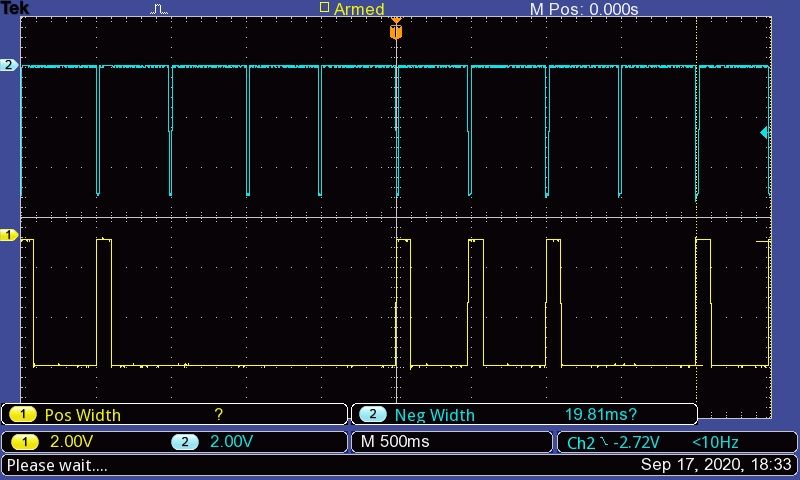
Although the magnet holder could be modified to hold the beam breaker sensor at 'centre', I decided to leave it offset. This is based on another unproven notion, which is that changes in amplitude can be detected by comparing the time spent by the bob on each side of the sensor. I believe time spent left of my offset sensor decays faster than time spent right of it. So the mark space ratio can be used to detect if amplitude is increasing or decreasing, and used to regulate impulse strength. A high-amplitude pendulum is closer to 50:50 than this example:

Last night's test run is promising, and has spawned some new ideas. The clock is on the dining table in my south facing radiator about 1m away from the window and central heating radiator. Shield off.

Weakish correlations are detected between period and both humidity and temperature. There's a major disturbance just after 7am. My first thought was it's due to temperature resulting from my central heating firing up. However, as I've had bother with the beam breaker sensor, I think it's more likely to be daylight. The vertical blue and red lines show civil twilight and sunrise respectively. I suspect increasing light falling on the sensor alters the impulse trigger point.
My simple amplitude regulator is akin to the hit and miss device used on old single cylinder oil engines, and amplitude gradually decaying overnight shows it's not quite set right. A more linear algorithm would help, but I need to re-test with the shield in place first. Also, an IR level sensor should be added to log ambient brightness.
Dave
Edited By SillyOldDuffer on 19/10/2020 12:22:17
SillyOldDuffer.


