Back to the clock! My vacuum pump is working well enough to proceed. Pumping out the clock shield doesn't cause it to collapse, or even to bend noticeably, which fits in with Fusion360's FEA which said my drain pipe concoction has a 15X safety factor.
Despite the awful noise the pump makes I could hear shield hissing due to leaks. Looking at the ends of the pipe showed my band-saw hadn't done a marvellous job; cut not quite square, visible tooth-marks, and a bump where the pipe separated.
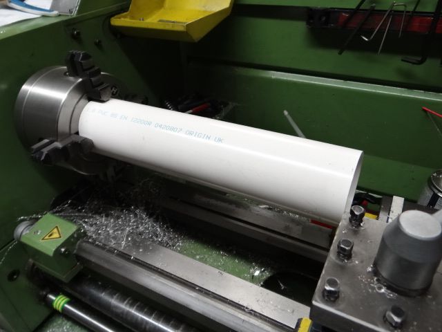
The obvious way to square and polish it off was in the lathe:

One end is poorly supported by the chuck and the other is in mid-air. All the red lights are flashing. Worth a try with soft plastic and a sharp cutter, I thought. Silly me. It's a Widow Maker! One touch with the cutter and the pipe ejected violently, nearly jambing between the jaws and the bed before bouncing off and landing on my foot. A metal pipe could do a lot of damage.
Still trying to think of a quick simple way of supporting the pipe, but I tied the ends up with a set-square, file, and sand-paper. Considerable improvement: with the pump running I was unable to pull the end-cap off bull-worker style The area of the end-cap is about 6 square inches, so I guess the vacuum was at least 10psi below atmospheric (ie about 60lbs holding the cap on.)
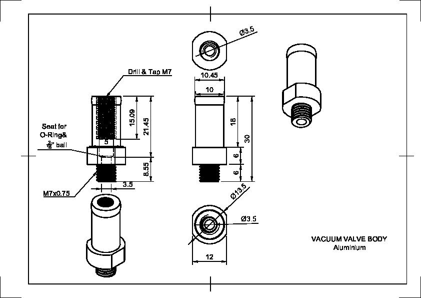
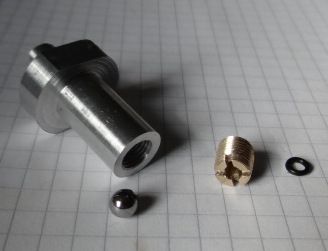
Next step, my vacuum valve:

Nothing special, the ball bearing keeps the valve sealed under atmospheric pressure and the brass thingy stops the ball bearing from coming out. After a sharp tap with a hammer seals fairly well, but the O-ring makes leaks worse. I think this is because the O-ring should squidge into a squared corner, whereas mine sits in a cone. Any o-ring experts out there?
At the moment the vacuum holds for only about 8 seconds after the pump is switched off, which is poor. The leaks need more attention. The pipe ends need polishing. Maybe thread sealant?
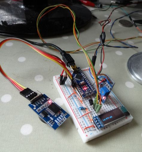
Meanwhile the electronics and software have been improved by adding a display and a Real Time Clock module. The RTC is a diagnostic aid – it lets me compare pendulum time with an accurate clock for debugging purposes.

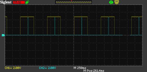
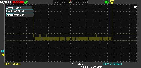
For example, the RTC confirms the clock runs for about 75 minutes before the pendulum becomes unstable, and also that pendulum seconds and real seconds are similar. Tuning the impulse has the clock running on 2mS pulses. The timing isn't quite correct, so smaller pulses should be possible. At the moment the pendulum gradually builds momentum until it bumps a pillar and crashes. (Design intent is a swing under 5°!) Not difficult to tweak the code to make pulses with microsecond resolution.
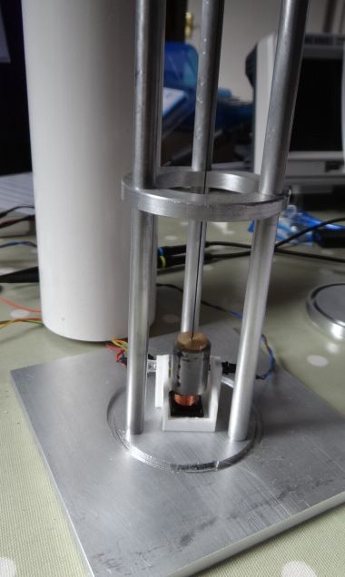
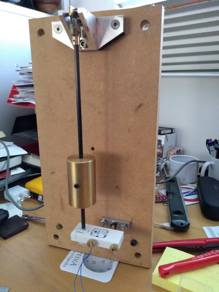
A second fault is due to the electromagnet being glued in off centre. If the pendulum doesn't get a clean start, it takes a diagonal course, which tends to go elliptical, and eventually the bob bumps into a side cheek and crashes. The thin carbon fibre rod does nothing to stop this. I'll upgrade the 3D printed magnet holder by adding a couple of locating rails so the magnet has to sit straight. As can be seen below there are only a few millimetres clearance between bob and cheeks. As the beam breaker is vulnerable to sunlight might be worth printing the holder in black plastic.

Another embarrassment: there's no way of leading the wires outside the shield. The shield can't be put on the base, let alone pumped out.
Hours of fun ahead…
Dave
Edited By SillyOldDuffer on 29/09/2020 16:35:00
SillyOldDuffer.


