Arduino Pendulum Clock Design – Comments Welcome

Advert

Arduino Pendulum Clock Design – Comments Welcome

Home Forums Clocks and Scientific Instruments Arduino Pendulum Clock Design – Comments Welcome

Viewing 25 posts - 51 through 75 (of 307 total)
  • Author
    Posts
  • #494858
    Peter Bell
    Participant
      @peterbell11509

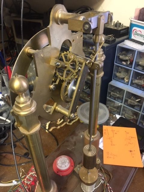
      Really interesting to follow this thread. I made the John Wilding "Simple Electric Clock" in 1987 and soon found it to be very unreliable. It works on the Hipp principle and the contacts were forever going out of adjustment and needing cleaning. Adding some transistors to help the switching didnt help so it was forgotten for years.

      Eventually replaced the Hipp arrangement with two magnetic sensors (optical sensors soon failed with dust?)and 555 timers to control the pulse and it worked but soon found that the soft iron core of the magnet was magnetising the swinging armature and eventually becoming unreliable and stopping, abandoned again!

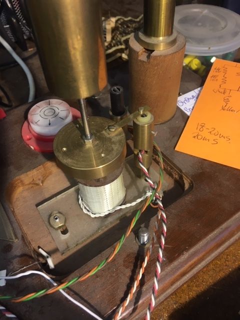
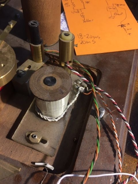
      Fast forward a few more years and I made an energising coil without an iron core (fine wire 2K ohms) and replaced the swinging armature with a 6mm neodymium disc magnet so that there was no interaction when swinging and unenergised..On the 555 it worked but was complicated. Discovered Picaxe micros and got a version working after learning some programming. Eventually moved onto Arduino and the latest version measures the pulse width with a magnetic sensor and stops energising the coil when a predetermined pulse width is reached. When its being energised by the Arduino the armature with magnet is pushed away.

      Been going a few months now and think its the best I've managed to get it running. The pundulum is on knife edges and quite a bit of friction in the train which I've reduced. but could be improved on.

      Not in the precision league I'm afraid that Dave's trying for but I'm pleased with the progress!

      Peter

      10.jpg

      12.jpg

      13.jpg

      Advert
      #494944
      SillyOldDuffer
      Moderator
        @sillyoldduffer

        Nice clock Peter! Hard to beat the character added by brass and moving parts; people like it. I like it!

        Mine has no aesthetic qualities whatever. With the shield on it looks exactly like a foot of old drainpipe! The technical interest must be an acquired taste. My family think I'm daft! What's it for?

        Thanks for confirming the iron core issue; it's on my 'fix' list. Also for the pulse width hint.

        Cheers,

        Dave

        #494951
        Martin Kyte
        Participant
          @martinkyte99762

          I was fortunate to be able to source some Swedish Iron for my Synchronome electromagnets.

          PS You know when you are on th eright track when people think you are daft.

          regards Martin

          #494989
          duncan webster 1
          Participant
            @duncanwebster1

            Really like Peter's clock.

            For iron with no residual magnetism try old transformer laminations. Not easy to make it round, but no-one said cores have to be circular. Perhaps others could comment on the use of ferrite aerial cores, I have no idea.

            Another approach to a central impulse self starting pendulum might be the Brillie style.

            **LINK**

            This could be duplicated with a neodinium magnet fastened to a curved brass member fixed to the end of the pendulum so the magnet swung through the coil

            And in response to Martin's final sentence, most people think I'm barking mad!

            #495030
            John Haine
            Participant
              @johnhaine32865

              One thing to remember is just how little energy is needed to keep the pendulum swinging. Mine gets impulsed once a minute by allowing a weight of ~10g to drop 2mm, or about 2e-4 joules. That's a dissipation in the entire system of 3.3 microwatts. Only a tiny force is needed to replenish the lost energy. With a neodymium magnet an air-cored coil will be fine and eliminate any concern about remanent flux. You can always increase the current, efficiency isn't really an issue.

              Though it never got into a finished clock I experimented with a wound bobbin removed from a printer with its core removed (it worked some sort of interlock) and a 1x3mm neo magnet on the end of the rod and there was clearly far more force than needed even for moderate current.

              #495043
              Peter Bell
              Participant
                @peterbell11509

                My high friction clock is impulsed for 80ms but will run with a pulse width of 40ms. The magnetic sensor looks for a pulse length of 20ms before switching off and it can only manage a couple of swings before its re-energized .

                If I switch off completely it takes 10 secs before it stops incrementing the count wheel and approx 60 secs before the pendulum is stationary. It takes a tiny push to get it going and around 30 secs to build up sufficiently before it is up to full swing and limiting.

                Its quite nice to stop the clock and see it build up again with the led in series with the coil flashing then stop and bounce on/off when its limiting!

                I have another more conventional experimental pendulum running on a similar impulse system but pre arduino which uses a pulse on time of around 5ms but its not driving anything.

                Peter

                #495046
                SillyOldDuffer
                Moderator
                  @sillyoldduffer
                  Posted by John Haine on 10/09/2020 10:41:11:

                  One thing to remember is just how little energy is needed to keep the pendulum swinging. Mine gets impulsed once a minute by allowing a weight of ~10g to drop 2mm, or about 2e-4 joules. That's a dissipation in the entire system of 3.3 microwatts. Only a tiny force is needed to replenish the lost energy. …

                  Started reading Woodward's "My Own Right Time" which arrived yesterday. Excellent complement to "The Science of Clocks and Watches". Lot to take in though!

                  The tiny amount of energy needed to keep a pendulum swinging makes it less likely that the Arduino will dominate the pendulum I hope. Martyn has me twitching. As Woodward describes how to measure Q more simply than I knew, I'll have a go at that next. If my pendulum takes a lot of energy to keep swinging (low Q), then the risk the Arduino is accidentally dominating the pendulum is higher than if the pendulum is high Q and the Arduino only pulses it at low level.

                  I've corrected the start problem: someone who shall remain nameless messed with the Arduino code while checking pulse timings with his oscilloscope and forgot to put it back…

                  Dave

                  #495286
                  SillyOldDuffer
                  Moderator
                    @sillyoldduffer

                    Measuring Q is a complete fiasco and the last attempt ended with me knocking the clock over. The method I'm using would take about 20 minutes on an ordinary pendulum clock; on this thing everything is against me. I keep disturbing the bob by bumping the table, and the cat is a menace. The tripod construction and tight space inside make it hard to measure amplitude because there's always something in the way. Also tricky to start the pendulum running straight by hand. Takes a long time to do the observations and I've yet to get a trustworthy result. Frustrating.

                    Plan B is to 3D print the magnet assembly and fit the IR beam to establish Q. Now where the h*ll did I leave the 3D printer's SD card?

                    Argh

                    Dave

                    #495810
                    SillyOldDuffer
                    Moderator
                      @sillyoldduffer

                      Bit of progress.

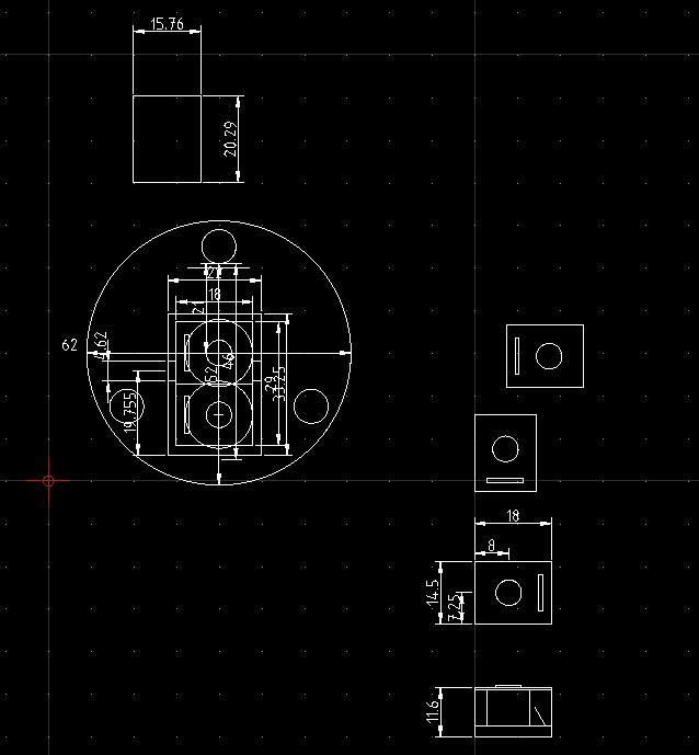
                      I used Qcad to layout a plan of the clock base using the dimensions of the bob and magnets etc. I find it easier to do this sort of work in 2D.

                      clockbaseplan.jpg

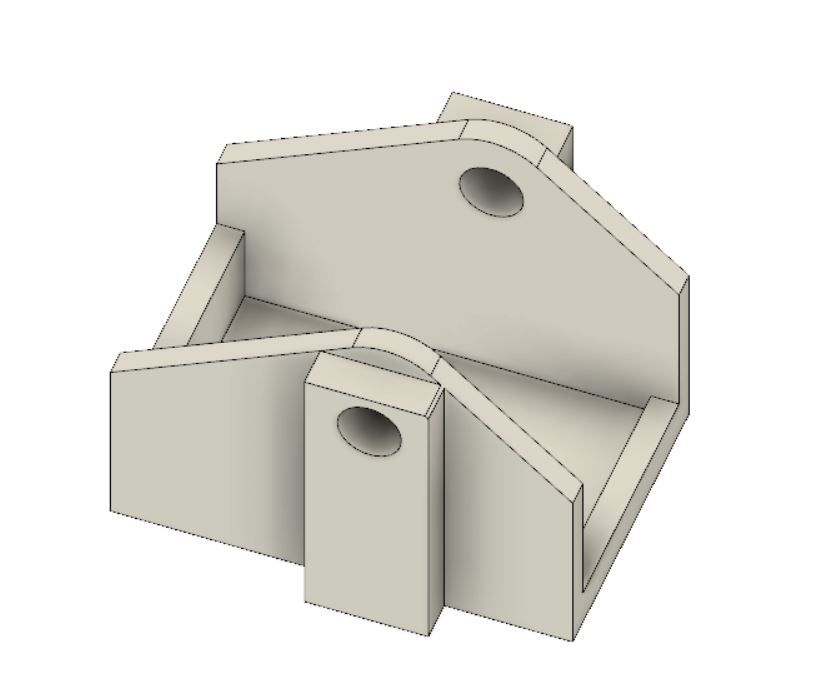
                      Having established the fit in 2D, I moved to Fusion 360 and designed a box to hold two electromagnets with cheek pieces to hold the IR LED and detector.

                      clockmagnetbase.jpg

                      The idea is to use one magnet at the side to start the pendulum swinging from rest, and the other underneath to impulse the bob. One end-wall is lowered so the 'start' magnet rests on it and tilts towards the bob. This late change bit back.

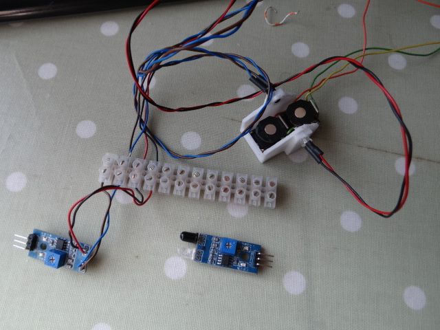
                      Exported the F360 design as STL and printed it via gcode with my Creality Ender 3D printer. Shown below with magnets glued in and the infra-red components plugged into the cheeks.

                      dsc06308.jpg

                      Below right under the terminal strip is an unmodified Arduino IR Proximity detector module. Normally the clear LED emits a beam that bounces back off obstacles and is detected to stop a robot hitting something. The module contains a comparator chip and sensitivity adjustment pot. Rather than design and build my own circuit, I modified a module simply by extending the LED and detector on wires.

                      Fans of duffer cock-ups will note the terminal strip swaps the connectioms over. Despite making notes and marking the LEDs to make sure they were reconnected the right way round, I soldered them back onto the module the wrong way. Ho hum.

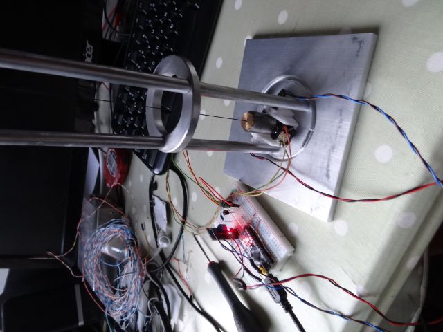
                      Here it is connected and assembled for first fitting. Nothing is fixed down yet.

                      dsc06310.jpg

                      Although it looks reasonable, it's a very tight fit. I failed to allow space for the IR beam wiring. Worse, because the electromagnets are rectangular and asymmetric, the bob was pulled off centre. Rearranging the magnets fore and aft to correct that means the poles can't quite be positioned correctly under the bob. Might work but it's way off design.

                      I'll probably go back to a single electromagnet to test the pendulum while rethinking the dual coil idea.

                      Dave


                      Edited By SillyOldDuffer on 14/09/2020 20:26:54

                      #495828
                      Marcus Bowman
                      Participant
                        @marcusbowman28936

                        I have had a test rig sitting on my bench for a while. It is a half-second pendulum suspended on a carbon fibre rod, and has a samarium-cobalt magnet attached under the pendulum. It originated with a series in ME by Dick Stephen. I built the rig because here were problems with the timing circuit and I thought I could do the job another way, using a microprocessor. There is a flat coil (no centre iron) which acts both as detector and as impulser (at least that's he theory). The original used two concentric coils, one for sense and the other for impulse, but I think more than one coil is unnecessary.

                        The pendulum will auto-start if timed pulses are applied to the coil.

                        The problem is that because the magnetic field is doughnut-shaped, the pendulum will tend to move in a slightly circular or elliptical path. Restraining the pendulum will mean frictional forces probably at the sides of the ball bearing at the top of the pendulum shaft. I am uncertain whether the fore-and-aft tendency is a result of the magnetic field, or simply created by minor random sideways forces – despite careful leveling of the rig, a rigid bench, and a concrete floor.

                        One of the problems with this kind of system, as Dick Stephen found, is that regular pulses tend to produce over-swinging, taking the pendulum far from any intended isochronous arc. Yes; we are trying to create a stable oscillator, but it must be resonant at the pendulum's natural frequency.

                        I don't think that a plan to apply regular pulses to the pendulum is necessarily a good way to ensure the pendulum swings at its own natural (resonant) frequency, and my plan is to use a statistical approach to try to identify what that frequency is, then try to maintain it. That means the adjustment of the frequency of swing will be by altering the effective length of the pendulum, which is what you would do on a mechanical clock, rather than attempting to drive the pendulum at a particular frequency to force it to time.

                        This is not a particularly urgent project. It has been maturing on the far end of the bench since 2007, and gets attention as the muse comes upon me.

                        It will be interesting to see your own results.

                        Marcus

                        #495844
                        Peter Bell
                        Participant
                          @peterbell11509

                          Reading the post from Marcus made me realise where I got the inspiration to try an energising coil without a core, it was from reading the Dick Stephen article and was a breakthrough moment for me.

                          I also considered that the magnetic field would be a srange shape without a core to concentrate so I used iron filings on a sheet of paper above the coil and got a result with a dead position in the middle so I thought I had the centre of the bobbin was too large, however it worked fine on my simple clock pushing the magnet out of the way once started until the detected pulse width stopped over swinging..

                          I considered that the swing was going to be eliptical, my question is how can the circular error of the pendulum be measured, apologies if it's already been covered somewhere? Did wonder about a laser mounted on the swinging pendulum bob shining onto a card or something?

                          Peter

                          #495847
                          John Haine
                          Participant
                            @johnhaine32865

                            Peter, what do you mean by circular error? It has a specific meaning in horology, being the increase in period with amplitude. Do you mean this, or the ellipticity?

                            #495859
                            John Haine
                            Participant
                              @johnhaine32865

                              Regarding elliptical swinging, this can happen if the impulse is not exactly coaxial with the bob, but also if the axis of suspension is not quite orthogonal to the suspension. For example, often the suspension has a back-to-front pivot to allow the pendulum to hang vertical, but if this has some stiction it may settle slightly out of vertical. Then when the bob swings in the "wanted" direction there will be a small force in the back/front plane so the pendulum will swing in that as well though with low amplitude. Usually the length in that plane is slightly longer so the period greater too, so the axis of ellipticity can precess – such behaviour has been observed. The period of the wanted resonance will also slightly wander at the difference frequency.

                              I'm not sure I understand the logic of a pancake coil. A simple solenoidal coil seems intuitively to be better as it focuses the impulse and the sensing too if dual purpose. Also is probably easier to adjust to get it on-axis.

                              #495860
                              John Haine
                              Participant
                                @johnhaine32865

                                There is a beautifully simple scheme for using an Arduino to drive one of these magnetic pendulums here. The code has 6 lines in its main loop().

                                #495878
                                Michael Gilligan
                                Participant
                                  @michaelgilligan61133
                                  Posted by John Haine on 15/09/2020 09:19:59:

                                  There is a beautifully simple scheme for using an Arduino to drive one of these magnetic pendulums here. The code has 6 lines in its main loop().

                                  .

                                  Great link, John … Thank You !

                                  This reduces the drive ‘mechanism’ to what it should be [a motor]

                                  … leaving experimenters free to concentrate on the timing performance that can be extracted from a pendulum.

                                  MichaelG.

                                  #495880
                                  SillyOldDuffer
                                  Moderator
                                    @sillyoldduffer
                                    Posted by Marcus Bowman on 14/09/2020 23:31:42:

                                    There is a flat coil (no centre iron) which acts both as detector and as impulser (at least that's he theory). The original used two concentric coils, one for sense and the other for impulse, but I think more than one coil is unnecessary.

                                    problem is that because the magnetic field is doughnut-shaped, the pendulum will tend to move in a slightly circular or elliptical path. Restraining the pendulum will mean frictional forces probably at the sides of the ball bearing at the top of the pendulum shaft. I am uncertain whether the fore-and-aft tendency is a result of the magnetic field, or simply created by minor random sideways forces – despite careful leveling of the rig, a rigid bench, and a concrete floor.

                                    One of the problems with this kind of system, as Dick Stephen found, is that regular pulses tend to produce over-swinging, taking the pendulum far from any intended isochronous arc. Yes; we are trying to create a stable oscillator, but it must be resonant at the pendulum's natural frequency.

                                    I don't think that a plan to apply regular pulses to the pendulum is necessarily a good way to ensure the pendulum swings at its own natural (resonant) frequency, and my plan is to use a statistical approach to try to identify what that frequency is, then try to maintain it. That means the adjustment of the frequency of swing will be by altering the effective length of the pendulum, which is what you would do on a mechanical clock, rather than attempting to drive the pendulum at a particular frequency to force it to time.

                                    Marcus

                                    Very instructive to compare and contrast how others approach these problems!

                                    Ages ago I made a single-coil sense/impulse pendulum driven on every swing by a couple of transistors. A Meccano novelty with a Super-magnet on the bob rather than a clock. Problem as Marcus says, impulsing caused the bob to gain energy – good fun watching it swing about 60°, but useless for time-keeping! Learnt it's hard to time and control impulse strength with electronics, because the circuit gets ever more complex as it's improved. Microcontrollers make the same job easy.

                                    Microcontrollers have a built in clock and manage multiple inputs and outputs with almost unlimited logical flexibility: many possibilities open up without needing a soldering iron.

                                    I dislike sense coils because they're slightly intrusive; generating electricity absorbs energy. While tiny the disturbance can be avoided with a beam breaking sensor. So my version doesn't have a magnet on the bob (plain mild-steel, maybe cast-iron later), and swings are detected with an infrared beam. The microcontroller can be programmed to impulse the pendulum whenever I choose and by altering the length of the pulse I can control the amount of energy applied to the bob. Also possible to program it to not pulse on every swing, and to measure the pendulums amplitude so it only impulses when needed.

                                    Agree it's vital not to force the pendulum. Martyn made the point earlier and it's still worrying me. Proving my clock depends on it's pendulum to keep time rather than being locked to the microcontroller's crystal oscillator is top of my 'to do' list once the clock runs.

                                    Another feature of my design is it doesn't matter much what the pendulum period actually is; there's no need to set it to a particular value. Instead, the period can be accurately measured – whatever it is – and the ticks converted to human display time by calculation in the microcontroller. In effect the clock's 'gear train' can be any ratio I want, and the rate.

                                    Doughnutting is another worry, or at least making sure the pendulum swings straight. My lightweight construction is asking for trouble; the bob only weighs 30g. I hope firing a short impulse at just the right time will minimise disturbance and the bob will always move towards the centre of the magnetic field. The field is generated with a relay coil, which is more sharply focussed than a pancake. What we're on to here is an example of noise, which I'm reading about in Woodward's "My Own Right Time". at the moment. Noise due to friction, temperature and pressure changes, and tidal effects on gravity etc. sets the ultimate limit on pendulum accuracy, so getting rid of avoidable problems is good. John Haine recommended Woodward earlier in the thread, and it's a good 'un!

                                    I may be doing something original, or not. As there's nothing new under the sun in that pendulum clocks have been intensively explored in the past, I'm a tad concerned I'm working on an idea not mentioned in the books because it's naive and doesn't work. Or just maybe development of pendulum clocks stopped slightly short of the art of the possible when they were surpassed by crystal oscillators. Keeping me amused however it ends up. If nothing else fans of traditional methods may get to enjoy me failing to produce an accurate clock despite modern 3D CAD, 3D printing, and advanced electronics!

                                    Dave

                                    #495881
                                    Martin Kyte
                                    Participant
                                      @martinkyte99762

                                      Agree it's vital not to force the pendulum. Martin made the point earlier and it's still worrying me. Proving my clock depends on it's pendulum to keep time rather than being locked to the microcontroller's crystal oscillator is top of my 'to do' list once the clock runs.

                                      John Harrison stated that "The Pendulum must have dominion over the escapement" which I find very usefull to return to when the risk of getting lost in the complexity looms large.

                                      My other question is does it matter if the pendulum moves in an ellipse provided the oscillations in each axis are independent.

                                      regards Martin

                                      #495884
                                      duncan webster 1
                                      Participant
                                        @duncanwebster1

                                        The problem of excessive amplitude mentioned by Marcus is what lead me to have an end of travel sensor and miss out the next pulse until it was back within bounds. Dick Stephen used a copper pate/magnet damper at the end of travel to take energy out, this didn't appeal to me at all. I seem to recall that this idea was used by Brille as well.

                                        The Minimag chap used to sell a kit for impulsing a pendulum as described in John Haine's link. Quick look on his website doesn't reveal it..

                                        I wish this issue hadn't raised its head as I've promised myself not to start anything else until I've actually finished some of the half complete jobs, but the temptation is getting too great. Get thee behind me Satan!!!!!!

                                        #495885
                                        duncan webster 1
                                        Participant
                                          @duncanwebster1

                                          The problem of excessive amplitude mentioned by Marcus is what lead me to have an end of travel sensor and miss out the next pulse until it was back within bounds. Dick Stephen used a copper pate/magnet damper at the end of travel to take energy out, this didn't appeal to me at all. I seem to recall that this idea was used by Brille as well.

                                          The Minimag chap used to sell a kit for impulsing a pendulum as described in John Haine's link. Quick look on his website doesn't reveal it..

                                          I wish this issue hadn't raised its head as I've promised myself not to start anything else until I've actually finished some of the half complete jobs, but the temptation is getting too great. Get thee behind me Satan!!!!!!

                                          #495886
                                          John Haine
                                          Participant
                                            @johnhaine32865
                                            Posted by Martin Kyte on 15/09/2020 10:45:55:

                                            ……………..

                                            My other question is does it matter if the pendulum moves in an ellipse provided the oscillations in each axis are independent.

                                            regards Martin

                                            Yes, because as soon as the pendulum moves out of its intended plane there is a coupling to the other mode, so if the modes are at different frequencies they will beat and the here will be a cyclic variation in the wanted period. Bob Matthys observed this, and at his request I built a simulation which also shows the effect.

                                            That's one concern I have about Dave's approach, that a thin CF "rod" used as a spring/rod combination will have a rather complex motion as the rod may not be circular – certainly the thin CF "wire" I have is decidedly out of round.  So the period in different planes could be different and they will inevitably couple.

                                            Edited By John Haine on 15/09/2020 11:04:05

                                            #495892
                                            Michael Gilligan
                                            Participant
                                              @michaelgilligan61133

                                              Bold assertion … Feel free to contradict me:

                                              It doesn’t matter a jot what path the pendulum describes, or the extent of its displacement … provided that it is consistent … The real problem is finding ways to achieve that consistent behaviour.

                                              That was the logic behind my first post, on p1 of this thread.

                                              MichaelG.

                                              #495905
                                              Martin Kyte
                                              Participant
                                                @martinkyte99762

                                                I can see possibilities of energy being transferred from one axis to the other via the escapement/impulsing system which was not my actual question which was for a pendulum alone. Perhapse I wasn't clear The periods must be identical as it's the same pendulum and provided the suspension is from a point I cannot see a mechanism for coupling or resonance.

                                                regrds Martin

                                                Edited By Martin Kyte on 15/09/2020 12:14:09

                                                #495925
                                                SillyOldDuffer
                                                Moderator
                                                  @sillyoldduffer

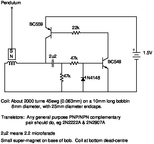
                                                  As an aside if anyone fancies swinging with a transistor circuit, this is what I used. Not sure were it came from.

                                                  pendswinger.jpg

                                                  Couldn't get an NE555 based circuit to work, at the time didn't have a scope. The transistors 'just worked'.

                                                  Dave

                                                  #495944
                                                  John Haine
                                                  Participant
                                                    @johnhaine32865
                                                    Posted by Martin Kyte on 15/09/2020 12:13:23:

                                                    I can see possibilities of energy being transferred from one axis to the other via the escapement/impulsing system which was not my actual question which was for a pendulum alone. Perhapse I wasn't clear The periods must be identical as it's the same pendulum and provided the suspension is from a point I cannot see a mechanism for coupling or resonance.

                                                    regrds Martin

                                                    Edited By Martin Kyte on 15/09/2020 12:14:09

                                                    For a pendulum suspended from a point with a massless, completely floppy and weightless string that's true. But a pendulum which has for example a conventional suspension, if for example the back-front axis is not orthogonal to the LR axis, in both planes, there will be coupling. Dave's pendulum has nearly a point suspension as it uses a CF rod which has some bending compliance, so its period is not fixed just by the bob but partly by the rod's springiness. If this is different for bending in different planes because the rod isn't exaclly round, this will make the period different for oscillations in different planes as well as introducing coupling.

                                                    If you consider a pendulum oscillating in a circular "ellipse" as an example, this is a "conical" pendulum and behaves rather differently from a conventional one. For example, its period decreases with increasing amplitude rather than increasing.

                                                    #495954
                                                    Michael Gilligan
                                                    Participant
                                                      @michaelgilligan61133
                                                      Posted by John Haine on 15/09/2020 09:19:59:

                                                      There is a beautifully simple scheme for using an Arduino to drive one of these magnetic pendulums here. The code has 6 lines in its main loop().

                                                      .

                                                      A quick question, if I may, John

                                                      … The iPad was playing ‘Nanny’ and not letting me view the downloaded code crying 2

                                                      I have worked-around that by opening it ‘as text’ in the Goodreader App

                                                      Could you please check that the following is complete and correct ?

                                                      __________

                                                      #define THRESHOLD 10
                                                      #define PUSH_TIME 30
                                                      #define A_PIN A0

                                                      void setup() {
                                                      pinMode(A_PIN,INPUT);
                                                      analogReference(INTERNAL);
                                                      }

                                                      void loop() {
                                                      if(analogRead(A_PIN)>THRESHOLD) {
                                                      pinMode(A_PIN,OUTPUT);
                                                      digitalWrite(A_PIN,HIGH);
                                                      delay(PUSH_TIME);
                                                      pinMode(A_PIN,INPUT);
                                                      }
                                                      delay(1);
                                                      }

                                                      __________
                                                      .

                                                      much appreciated

                                                      MichaelG.

                                                    Viewing 25 posts - 51 through 75 (of 307 total)
                                                    • Please log in to reply to this topic. Registering is free and easy using the links on the menu at the top of this page.

                                                    Advert

                                                    Latest Replies

                                                    Viewing 25 topics - 1 through 25 (of 25 total)
                                                    Viewing 25 topics - 1 through 25 (of 25 total)

                                                    View full reply list.

                                                    Advert

                                                    Newsletter Sign-up