Lots of posts and points for me to think about, so Bob Stevenson's request for info about the Clock Analyser first. It's not been written up as a project, but I could provide details if anyone fancies building it.
Processor is an Arduino Mega: similar to Nano or Uno but with more pins and memory. In this case, the extra pins are needed to drive a Sainsmart TFT Touch Screen. The master clock is a GPS module. GPS is the Achilles Heel of the project because it needs a good view of the Satellites. Works fine in my south facing dining room, no signal in my hallway. Not good for a portable analyser that's meant to work on clocks located anywhere in a house.
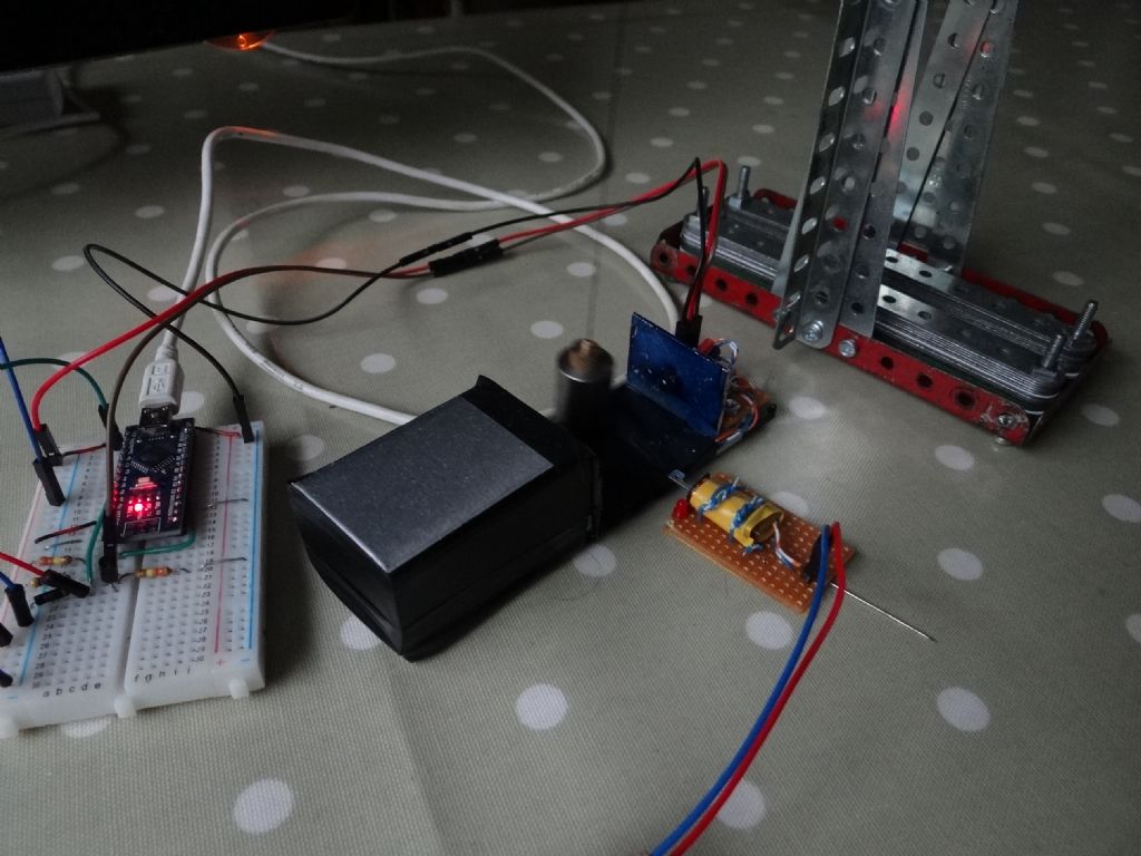
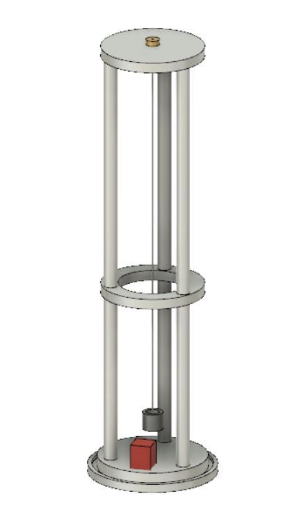
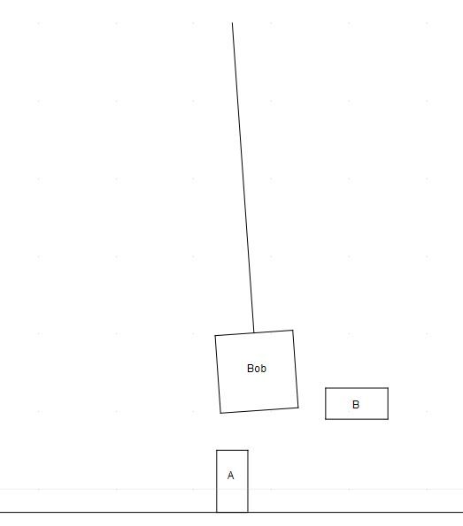
This picture shows a beam breaker sensor; Bazyle asked about sunlight, which is why the receiver is in a box and the aluminium faces are blued to reduce reflections. The same sensor is used here to pulse the test clock, yellow electromagnet from kitchen clock motor on right. Arduino Nano at left drives the test pendulum, the clock analyser is off-screen.

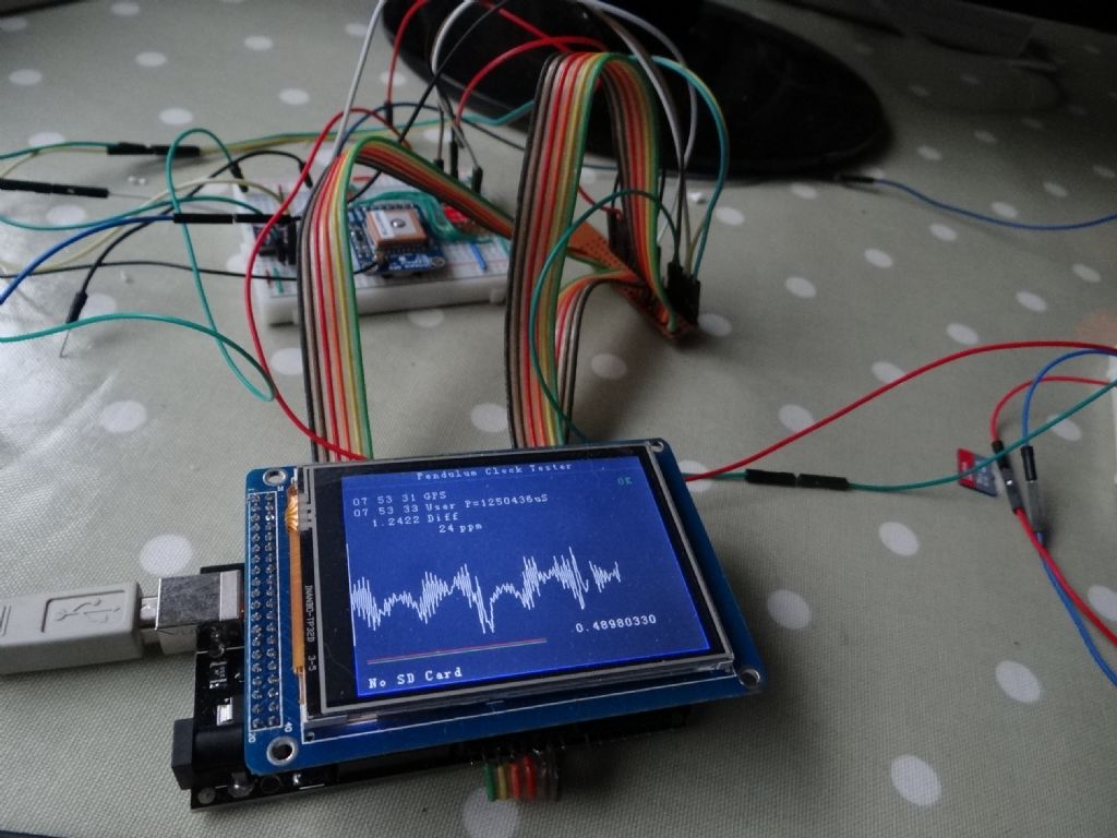
This is the Clock Analyser:

A TFT screen is mounted on top of the Mega. GPS Module on the breadboard above. The ribbon cables are soldered to a home-made plug header as a prototype / breadboarding convenience: in a real build I'd put the whole lot on Veroboard.
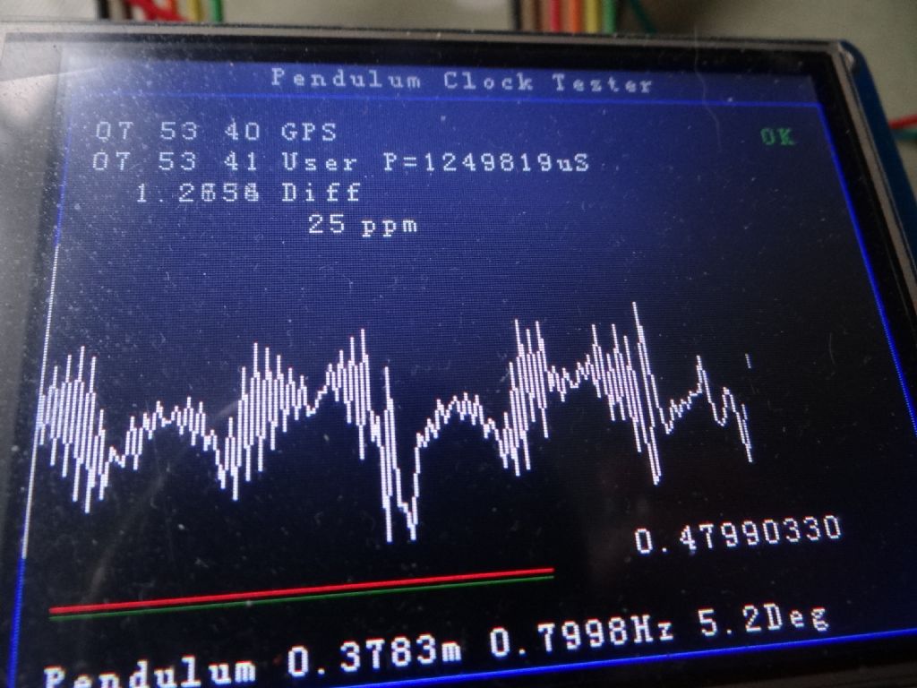
Close of the screen:

GPS time and Clock Time (based on counting swings), with difference in seconds. Green OK means GPS has locked on and is producing accurate second pulses.
Period of pendulum in microseconds (not accurate to the last digit)
The graph shows variation in pendulum time per swing. The graph is scaled to exaggerate perturbations, and the display ought to quantify them but deoesn't yet. From memory the difference between longest and shortest swing on this example is about 100uS. Although this pendulum varies swing by swing and has a superimposed cyclic variation, both effects average out.
The red and green lines and 0.4799 figure are tick-tock balance, ideally 0.5
Finally, bottom line shows length of pendulum calculated from simple formula, frequency in Hz from period, and estimated swing angle.
The source code for the analyser is here in Dropbox. The written description (odt document) is out-of-date.
Dave
Edited By SillyOldDuffer on 01/09/2020 13:02:05
SillyOldDuffer.


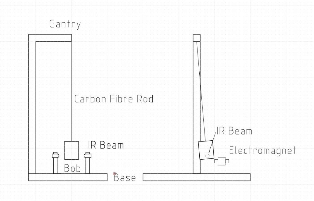
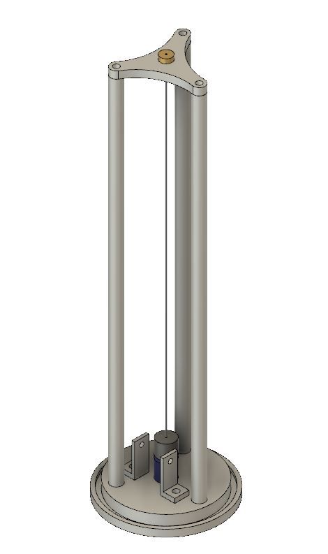
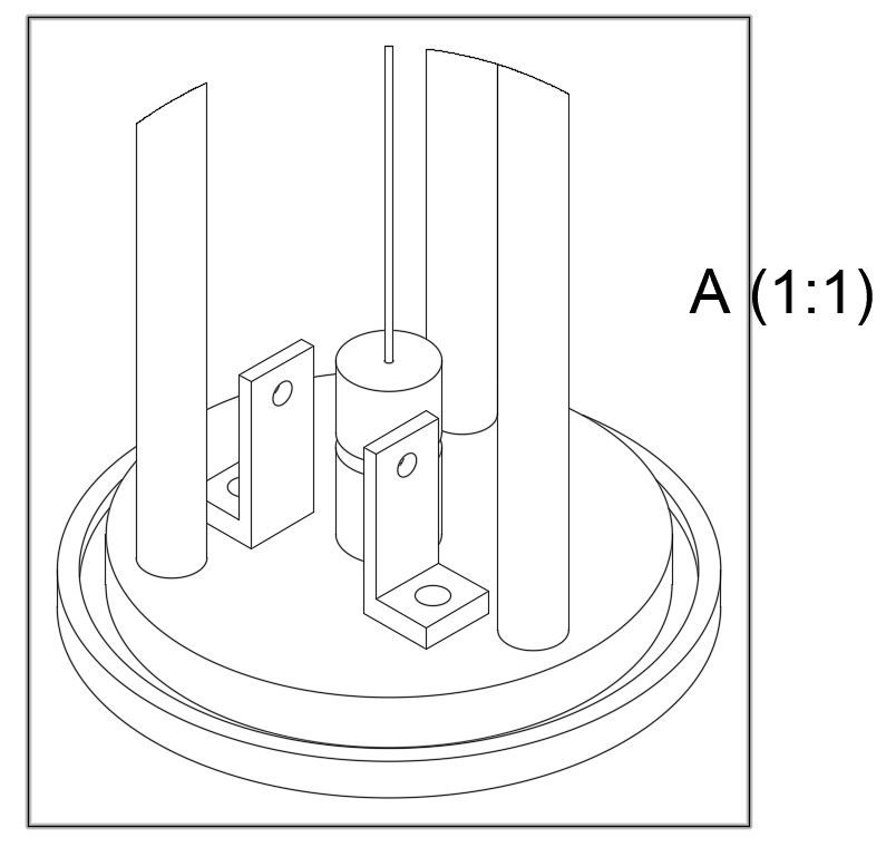
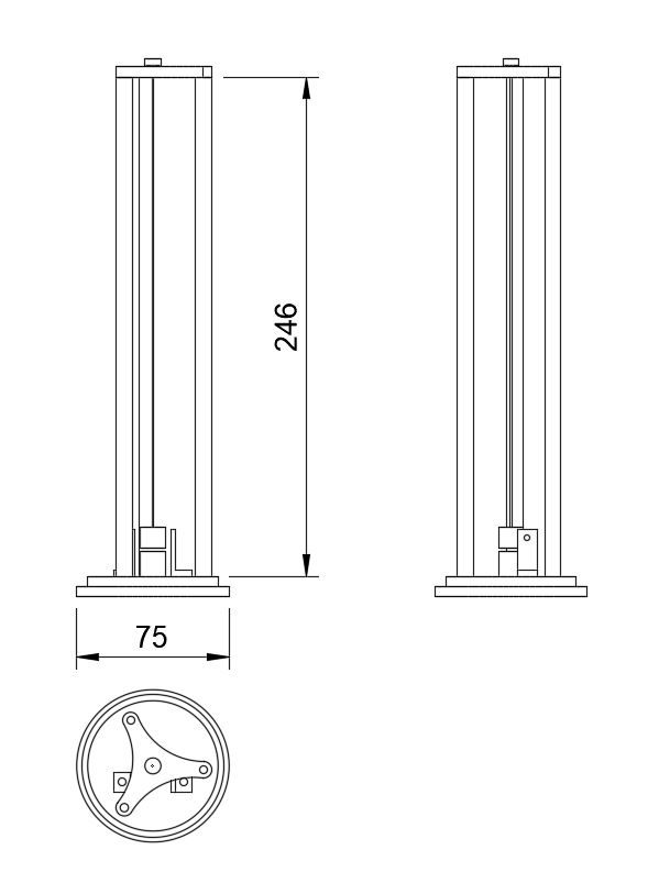
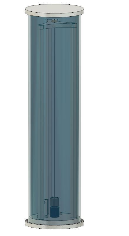
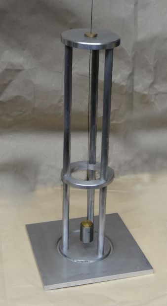
 which is working well. It does have a CF rod, but uses a stepper motor to operate the gravity arm every 30s. Sensing is optical, the pendulum period is fixed at just under 2 seconds, and the clock is mainly "rated" by adjusting the modulus of a counter that inhibits the pulse to the dial every so often (currently once every 158 swings). A few thoughts.