Arc tangent to two ellipses

Advert

Arc tangent to two ellipses

Home Forums Beginners questions Arc tangent to two ellipses

Viewing 24 posts - 1 through 24 (of 24 total)
  • Author
    Posts
  • #404520
    Ivan Ginato
    Participant
      @ivanginato28142

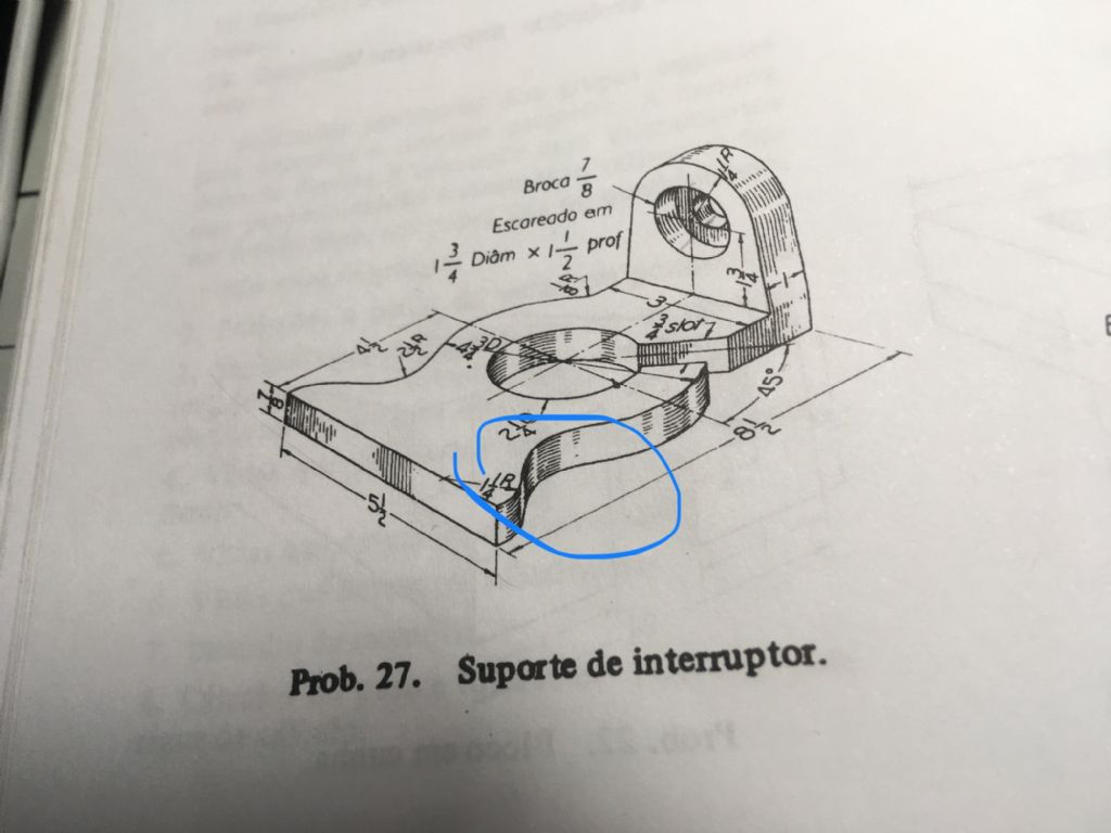
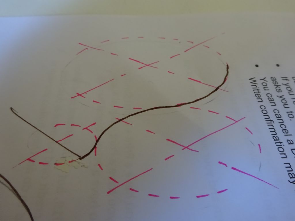
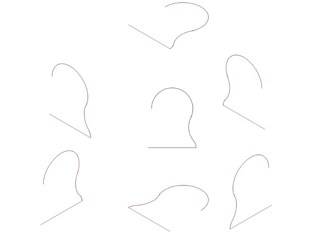
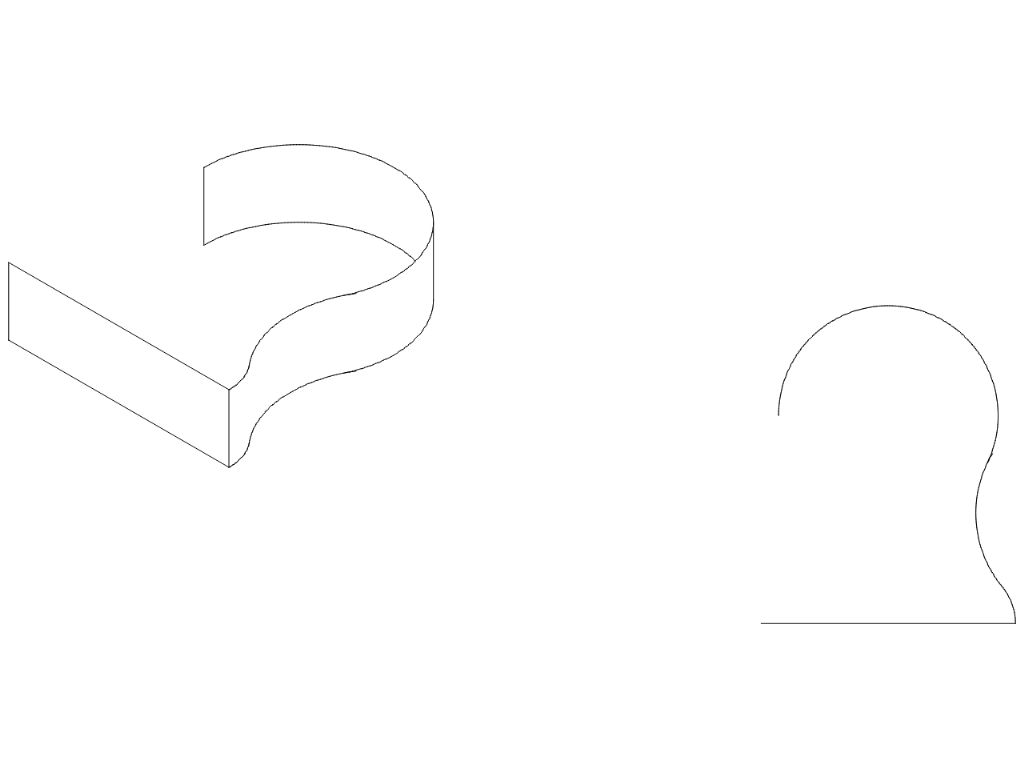
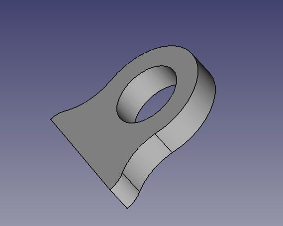
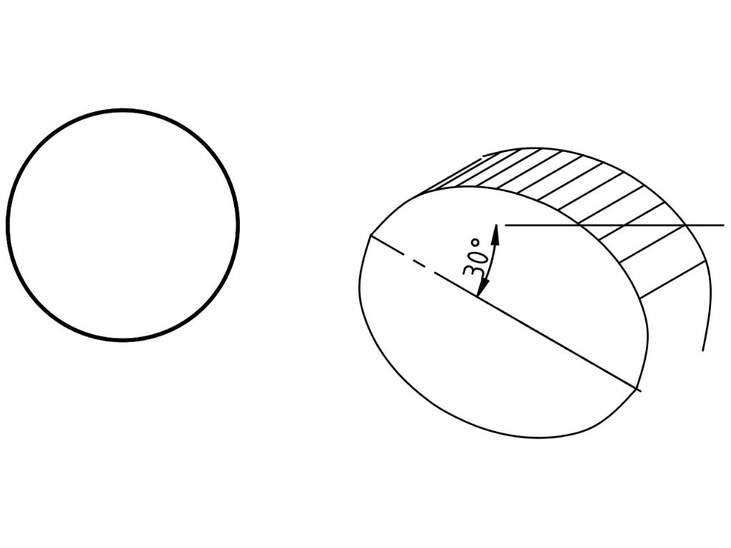
      I’have been practining my board drawing skills and I can’t understand how to draw a arc tangent to two false ellipse. Could someone help my? Following the model drawing and my drawing:

      Model drawing

      My drawing

      Advert
      #9618
      Ivan Ginato
      Participant
        @ivanginato28142

        Technical drawing

        #404522
        Ivan Ginato
        Participant
          @ivanginato28142

          I tried to draw the arc but it does not seem correct.

          #404581
          Perko7
          Participant
            @perko7

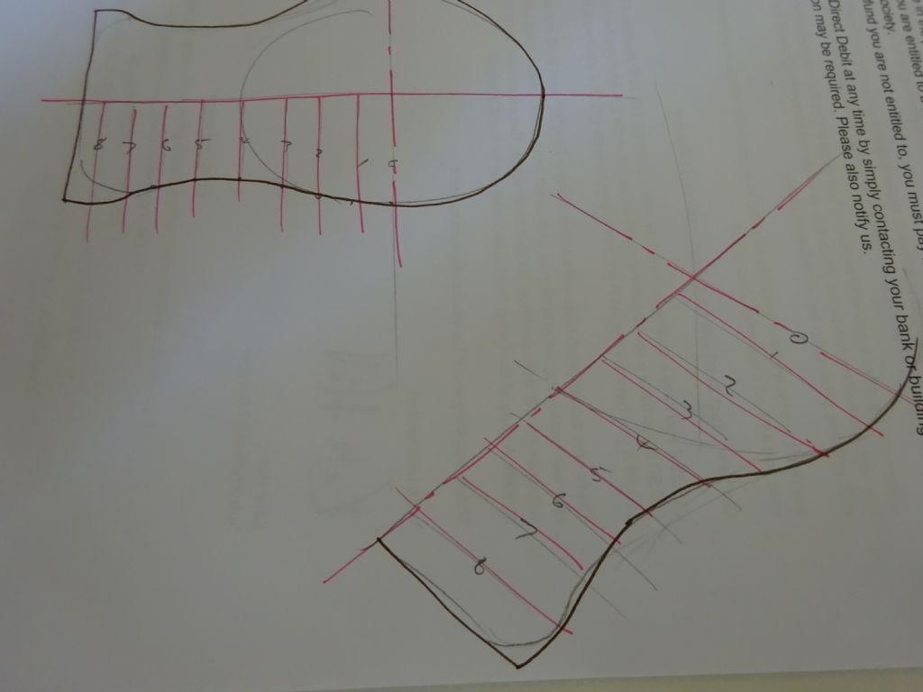
            When I did my tech drawing training back in 1970, we were taught to draw it out in plan and elevation first, then draw construction lines at regular intervals perpendicular to the long axis which intersect the arcs. Then we could measure the offset and repeat that for drawing isometric or oblique views. The curve then became a freehand 'join the dot's as it rarely was a constant radius. Hope this helps.

            #404586
            JasonB
            Moderator
              @jasonb

              It's times like this when an isometric ellipse template comes in handy, it is actually 3 ellipses joined together that you need.

              If not then as Perko says draw it out and construct a series of points then freehand the line between them.


              Edited By JasonB on 11/04/2019 10:17:28

              #404594
              SillyOldDuffer
              Moderator
                @sillyoldduffer

                tangents.jpg

                This is how I did it.

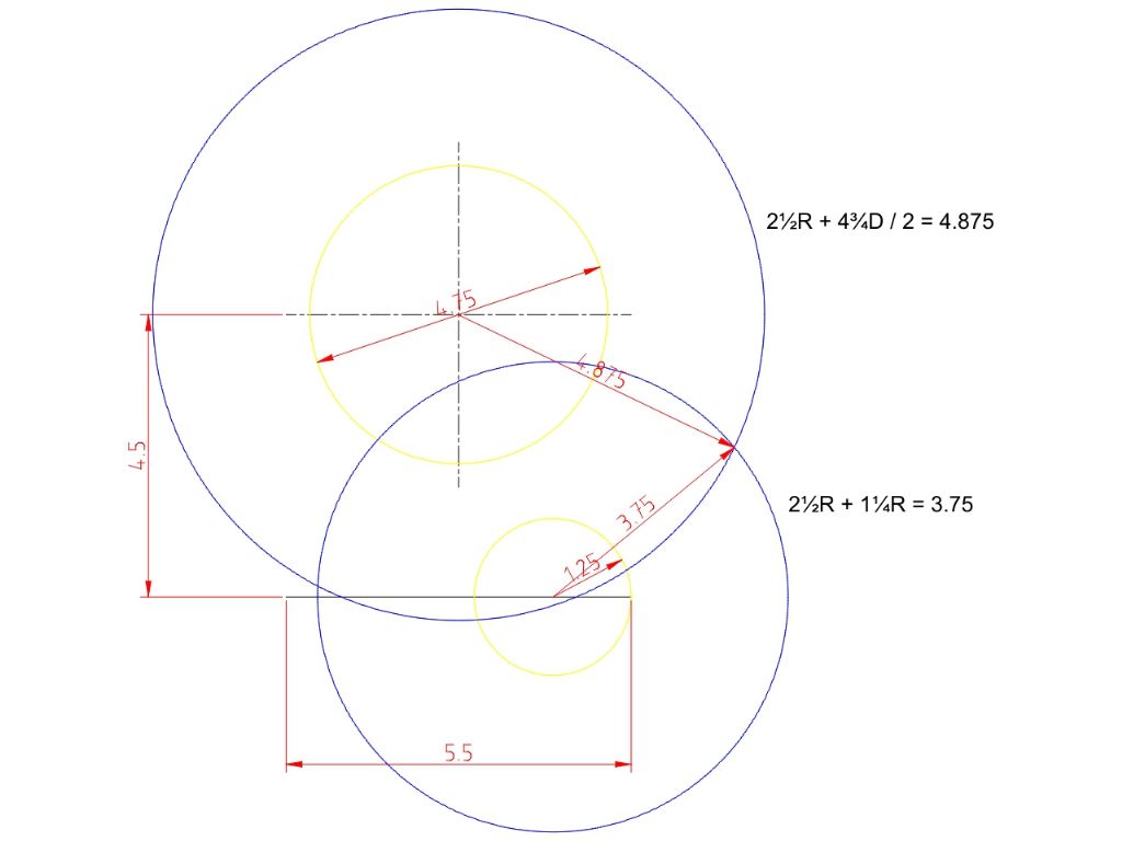
                First draw the centre lines and the 5½" line. Then draw (in yellow), a 4¾" construction circle on the centre, and a 1¼" construction circle on the end of the 5½" line.

                Next draw a construction circle (in blue) on the centre line that's 2½" larger in radius than the objects 4¾" diameter, ie. 4.875". Add a second construction circle (in blue) on the 5½" line that's 2½" larger in radius than the 1¼" lower radius curve, ie 3.75".

                tancon2.jpg

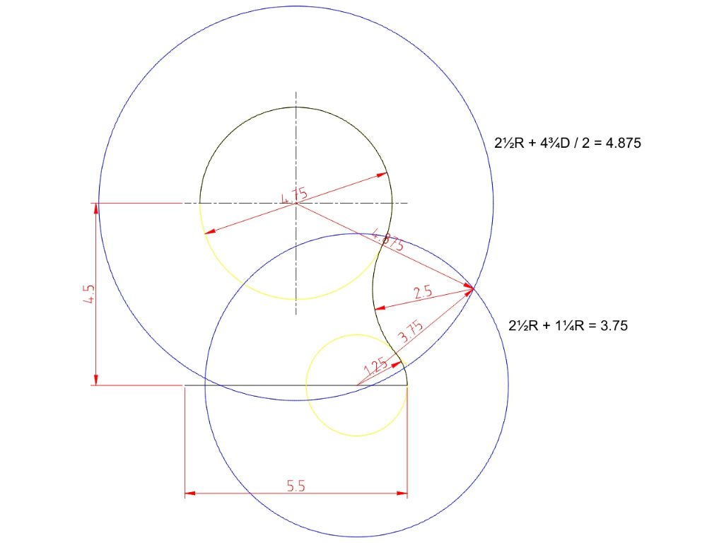
                The intersection of the two blue circles is the centre point of Ivan's required 2½" tangent curve:

                tancon3.jpg

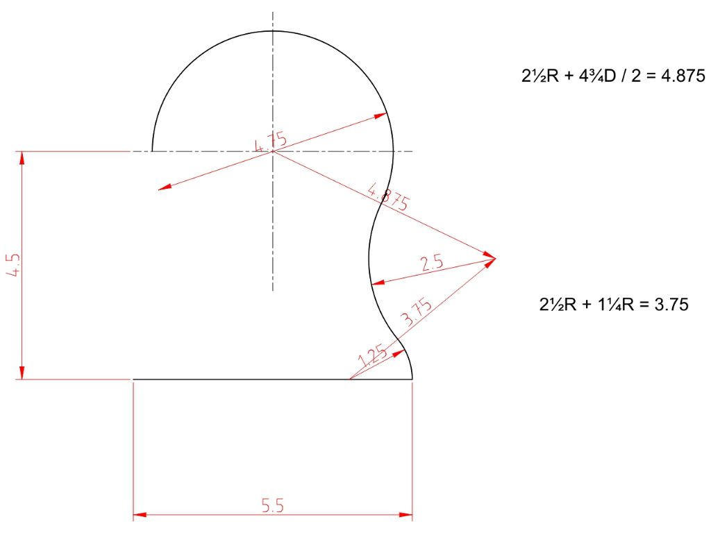
                Removing construction details:

                tanconfin.jpg

                Dave

                #404598
                JasonB
                Moderator
                  @jasonb

                  Dave, it's the isometric that Ivan is trying to draw (see his second link) hence the need for elipses.

                  dsc03576.jpg

                  Edited By JasonB on 11/04/2019 12:16:41

                  #404599
                  SillyOldDuffer
                  Moderator
                    @sillyoldduffer
                    Posted by JasonB on 11/04/2019 12:03:41:

                    Dave, it's the isometric that Ivan is trying to draw (see his second link) hence the need for elipses.

                    Oh dear, wrong again! Still, apart from that it was a good answer…

                    I shall have another think, this time with brain engaged!

                    Dave

                    #404601
                    JasonB
                    Moderator
                      @jasonb

                      Well not quite wrong as you do need to be able to draw the plan as per your method to get the lines to project.

                      The other option is to again work out the middle of the circle that forms the concave side and then just construct the three circles on one plane as ivan has done for the central circle. You then just draw around the line that the 3 circles form to get the edge of the part.

                      dsc03577.jpg

                      #404619
                      SillyOldDuffer
                      Moderator
                        @sillyoldduffer

                        Ivan's problem highlights the advantage of 3D CAD over pencil and paper methods and 2D CAD. For example, QCAD has basic tools that allows the draughtsman to nudge shapes into isometric form.

                        tanconqcad.jpg

                        The isometric lines are created by transforming and rotating the drawing. Might have a go at explaining the maths  but the number-crunching is quite involved.

                        Anyway, the nice QCAD-man programmed the maths so you just choose one of the views and manually use it to develop an isometric drawing by copying and adding lines. And then deleting any lines that should be hidden behind the object. Although QCAD does most of the maths and sorts out the ellipses etc, it's still hard work converting 2D into isometric:

                        tanqquadiso.jpg

                        In 3D CAD, much better:  the object is modelled and because the shape is fully defined in 3 dimensions, the computer can do everything needed, almost effortlessly. The object can be rendered as 2D drawings, with sections, or in isometric, perspective, and photo-realistic views from any angle.

                        tanfreecad.jpg

                        Isometric maths is really making my head hurt and I don't see why everyone else shouldn't suffer too!  Watch this space…

                        Dave

                        Edited By SillyOldDuffer on 11/04/2019 15:05:14

                        #404628
                        Neil Wyatt
                        Moderator
                          @neilwyatt

                          Do it the old fashioned way!

                          Get a set of French curves and choose the best fit by eye.

                          #404634
                          Ivan Ginato
                          Participant
                            @ivanginato28142
                            Posted by SillyOldDuffer on 11/04/2019 15:01:29:

                            Ivan's problem highlights the advantage of 3D CAD over pencil and paper methods and 2D CAD. For example, QCAD has basic tools that allows the draughtsman to nudge shapes into isometric form.

                            tanconqcad.jpg

                            The isometric lines are created by transforming and rotating the drawing. Might have a go at explaining the maths but the number-crunching is quite involved.

                            Anyway, the nice QCAD-man programmed the maths so you just choose one of the views and manually use it to develop an isometric drawing by copying and adding lines. And then deleting any lines that should be hidden behind the object. Although QCAD does most of the maths and sorts out the ellipses etc, it's still hard work converting 2D into isometric:

                            tanqquadiso.jpg

                            In 3D CAD, much better: the object is modelled and because the shape is fully defined in 3 dimensions, the computer can do everything needed, almost effortlessly. The object can be rendered as 2D drawings, with sections, or in isometric, perspective, and photo-realistic views from any angle.

                            tanfreecad.jpg

                            Isometric maths is really making my head hurt and I don't see why everyone else shouldn't suffer too! Watch this space…

                            Dave

                            Edited By SillyOldDuffer on 11/04/2019 15:05:14

                            Actually, I draw with paper and pencil as a hobbie. I've been studying AutoCAD and SolidWorks too. My teacher said me the paper and pencil method improve my horizon of imagination.

                            #404636
                            Ivan Ginato
                            Participant
                              @ivanginato28142
                              Posted by Perko7 on 11/04/2019 09:31:10:

                              When I did my tech drawing training back in 1970, we were taught to draw it out in plan and elevation first, then draw construction lines at regular intervals perpendicular to the long axis which intersect the arcs. Then we could measure the offset and repeat that for drawing isometric or oblique views. The curve then became a freehand 'join the dot's as it rarely was a constant radius. Hope this helps.

                              Either by i've never seen it before or by not being anglophone I can't understand this method. Actually I think it is like a development surface methods? Like the following image:

                              Development surfaces


                              Edited By Ivan Ginato on 11/04/2019 17:13:46

                              Edited By Ivan Ginato on 11/04/2019 17:16:01

                              #404637
                              JasonB
                              Moderator
                                @jasonb

                                It is a bit surface development, I illustrated the method earlier with this quick sketch

                                dsc03576.jpg

                                On the plan you draw a set of evenly spaced lines at right angles to one axis. Then on the Isometric draw the two axis with a 60/30degree set square and also use that to repeat the set of lines. You can then either measure the length of these lines on the plan view and mark the same lengths off on the isometric or use dividers to pick up the lengths and transfer to the isometric. Finally freehand join all the marks on the lines into a nice flowing curve.

                                If you want to see it done with more accuracy than the sketch just ask and I will dust of my drawing board.

                                Edited By JasonB on 11/04/2019 17:19:57

                                #404689
                                Perko7
                                Participant
                                  @perko7

                                  Yes Ivan and JasonB, it is surface development like you have stated, I just couldn't remember the correct terminology.

                                  Neil, I well remember the French Curves we used to use, never could get an exact fit but usually got close enough with a little angling of the pencil where necessary.

                                  Instead of free-handing, we used to use a flexible rule which was a rubbery/plastic 1cm square rod about 40cm long with a soft metal wire of some kind through the core. When you set it to a curve it would just stay there until you straightened it.

                                  #404693
                                  Michael Gilligan
                                  Participant
                                    @michaelgilligan61133
                                    Posted by SillyOldDuffer on 11/04/2019 15:01:29:

                                    The isometric lines are created by transforming and rotating the drawing. Might have a go at explaining the maths but the number-crunching is quite involved.

                                    .

                                    I will be interested to see your explanation, Dave

                                    MichaelG.

                                    .

                                    Sorry; I probably can't contribute for a few days, but it's something that I worked-out how to do in Autocad [early DOS version] more than 30 years ago … in just a few simple steps.

                                    #404728
                                    SillyOldDuffer
                                    Moderator
                                      @sillyoldduffer
                                      Posted by Ivan Ginato on 11/04/2019 16:54:55:

                                      Posted by SillyOldDuffer on 11/04/2019 15:01:29:

                                      Ivan's problem highlights the advantage of 3D CAD over pencil and paper methods and 2D CAD.

                                      Dave

                                      Actually, I draw with paper and pencil as a hobbie. I've been studying AutoCAD and SolidWorks too. My teacher said me the paper and pencil method improve my horizon of imagination.

                                      No criticism intended Ivan, my fault – I drifted onto CAD. I use paper and pencil too. The techniques used before computers are interesting and useful. Well worth looking at hand methods, for example, I find CAD drawings lack character compared with hand-drawn draughtsmanship, which can be beautiful.

                                      Dave

                                      #404729
                                      Circlip
                                      Participant
                                        @circlip

                                        "Instead of free-handing, we used to use a flexible rule which was a rubbery/plastic 1cm square rod about 40cm long with a soft metal wire of some kind through the core. When you set it to a curve it would just stay there until you straightened it."

                                        "Flexicurve" , square Lead core with two stainless strips encased in a soft PVC moulded sleeve. Easy way to straighten it was to "Whip" it onto the desktop. Have a later type made from interlocking plastic channel sections, can't get a tight radius, just like the FC. but a piece of solder helped.

                                        Regards Ian.

                                        #404762
                                        Cornish Jack
                                        Participant
                                          @cornishjack

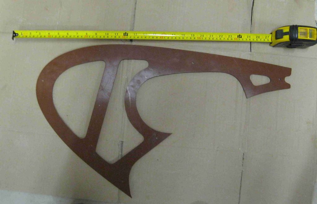
                                          Have had a 'Flexicurve' for many years and very useful too but was offered this, some years ago. It offers a reasonable variety.img_0029a.jpg

                                          Anyone care to hazard a guess as to its origin? Ex Weybridge chaps might be at an advantage!

                                          rgds

                                          Bill

                                          #404776
                                          Ivan Ginato
                                          Participant
                                            @ivanginato28142
                                            Posted by JasonB on 11/04/2019 17:15:47:

                                            It is a bit surface development, I illustrated the method earlier with this quick sketch

                                            dsc03576.jpg

                                            On the plan you draw a set of evenly spaced lines at right angles to one axis. Then on the Isometric draw the two axis with a 60/30degree set square and also use that to repeat the set of lines. You can then either measure the length of these lines on the plan view and mark the same lengths off on the isometric or use dividers to pick up the lengths and transfer to the isometric. Finally freehand join all the marks on the lines into a nice flowing curve.

                                            If you want to see it done with more accuracy than the sketch just ask and I will dust of my drawing board.

                                            Edited By JasonB on 11/04/2019 17:19:57

                                            I would not dare ask you to do it for me, but I would dare ask you some material, book, pdf etc about it. Actually at my school is not give importance to paper and pencil drawing then I am doing it by myself.

                                            #404778
                                            JasonB
                                            Moderator
                                              @jasonb

                                              Watch this

                                              #404779
                                              Ivan Ginato
                                              Participant
                                                @ivanginato28142
                                                Posted by JasonB on 12/04/2019 16:56:04:

                                                Watch this

                                                Ok. Really thanks, man!

                                                #404797
                                                SillyOldDuffer
                                                Moderator
                                                  @sillyoldduffer

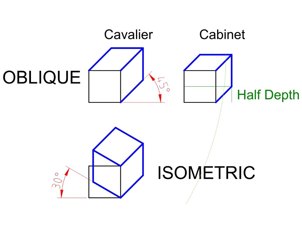
                                                  Slight diversion into the Oblique and Isometric Methods first.

                                                  Oblique, presented at a 45° angle is easier to draw than isometric because the front face doesn't move. The Cavalier form retains the correct depth dimension and looks odd, Cabinet halves the depth as shown and looks more like a cube. Isometric is rotated at 30° and looks better.

                                                  Note that none of these projections are trustworthy in terms of dimensions or angles, which is why they are unwelcome in the workshop.

                                                  obliosmetric.jpg

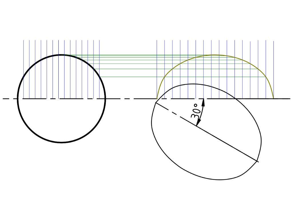
                                                  Similar to Jason's method, and as an introduction to how a computer might do an isometric projection:

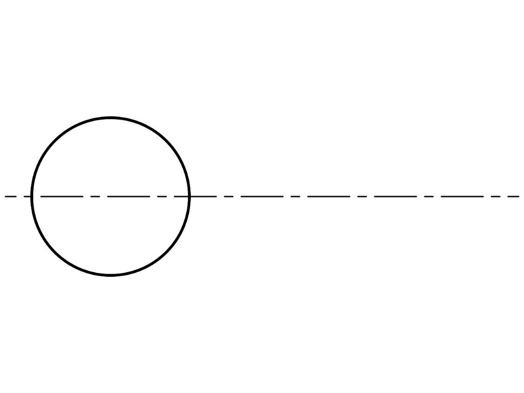
                                                  1. Draw a circle representing the end of a cylinder and, to show alignment, a centre line:

                                                  iso1.jpg

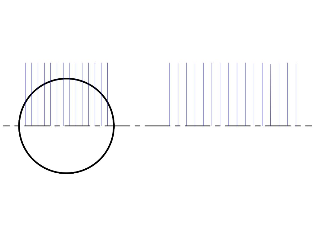
                                                  Next add two grids. Normally with the same separation, I've widened that on the right to emphasise the process – unnecessarily as it turned out. Doing this manually I used 15 grid lines, additional lines produce a more accurate ellipse but the process is a lot more work and pencil and paper limit the visible benefit. A computer has no such restrictions, the transformation can have as many points as wanted, which makes it possible to scale isometric drawings freely. 

                                                  iso2.jpg

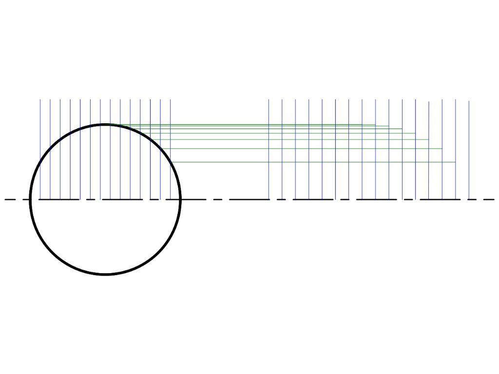
                                                  Add horizontals to map points from the circle to form an ellipse. This is a transformation, and it has the effect of producing new coordinates for the circle that make if appear to be turned sideways. Rather than drawing lines between grids on paper, transformations are done mathematically by the computer.

                                                  iso3.jpg

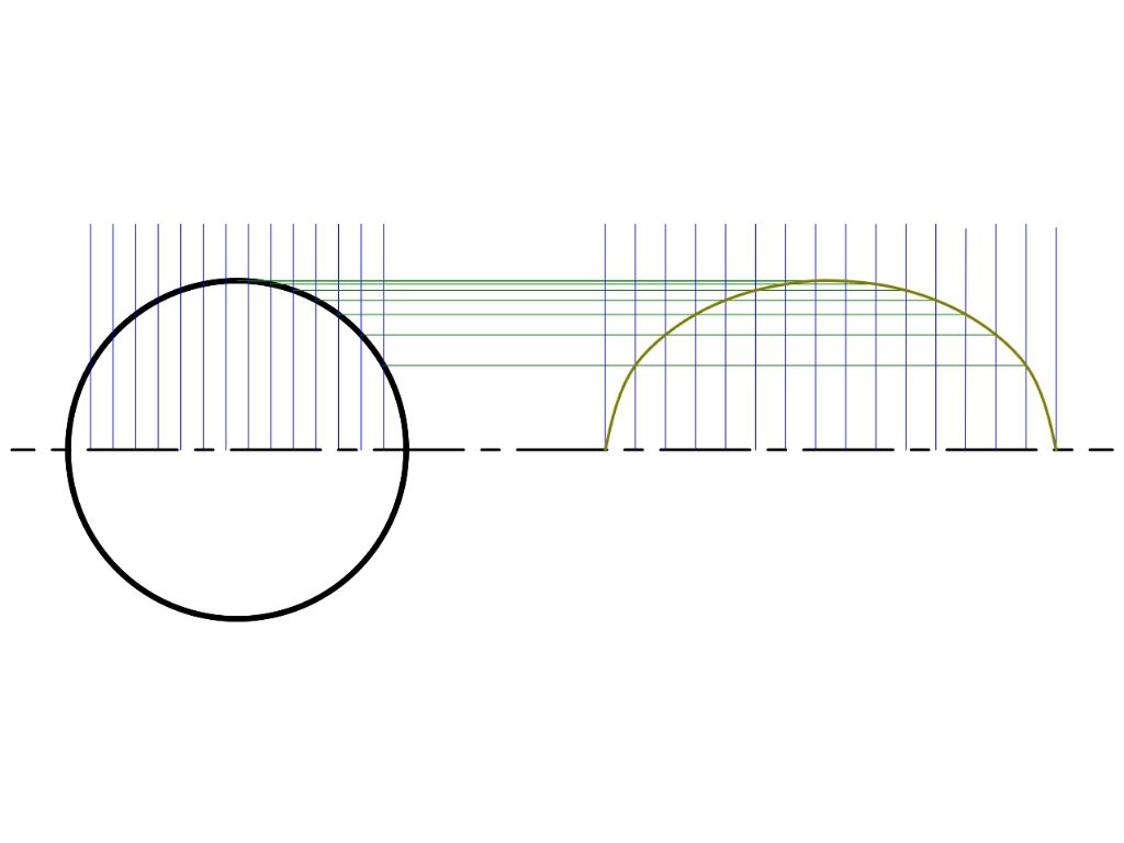
                                                  The ellipse is drawn by joining the new points.  All lines and shapes can be drawn by connecting points.

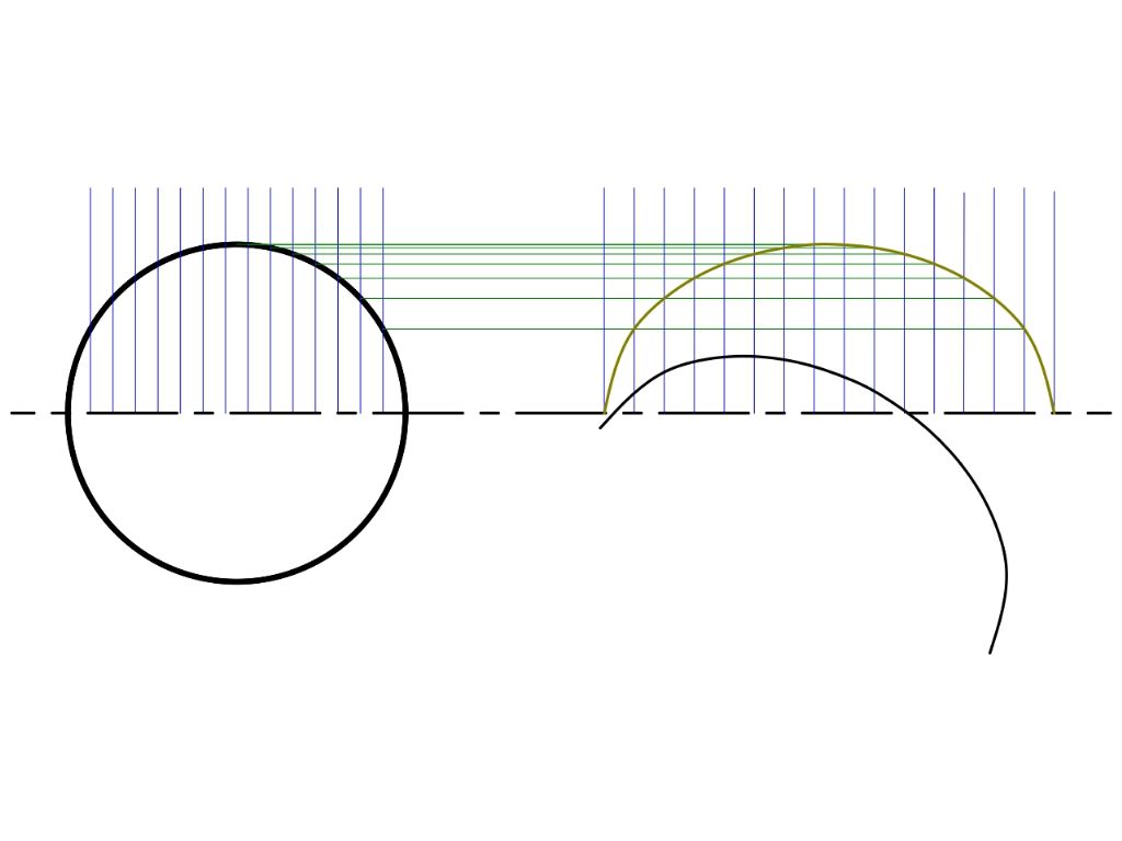
                                                  iso4.jpgThe ellipse is not yet in isometric form. It has to be rotated by 30°


                                                  iso5.jpg

                                                  The complete ellipse is produced by mirroring the top half, another numeric transformation:

                                                  iso6.jpg

                                                  Finally, the isometric depth is produced by replicating the top half of a the ellipse and moving it up and sideways:

                                                  iso7.jpg

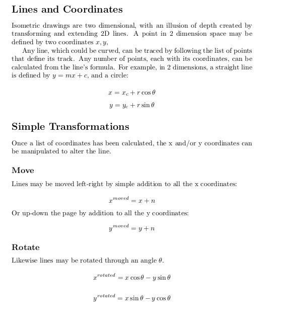
                                                  All this can be done by manipulating the x,y coordinates of the lines, here's an outline of the maths:

                                                  matrix.jpg

                                                  In practice transformations are performed using matrices. Matrices allow moves and rotations to be combined together, and, surprisingly, the computer instructions are more efficient than solving the equations one after the other.

                                                  Even in this simplified overview it's obvious that a lot of calculations have to be done. So many that the method isn't really practical for people. Fortunately computers are really good at high-speed maths. Just as well, because the much same calculations with the addition of z coordinates, are used to translate 3D models into CNC tool paths. No way can a CNC machine follow a French Curve or guess – it has to told exactly where to go next . Bodging curves is not allowed!

                                                  This has been another exercise in self education for me. Delighted to have mistakes identified and corrected!

                                                  Dave


                                                  Edited By SillyOldDuffer on 12/04/2019 18:43:35

                                                  #404837
                                                  Ivan Ginato
                                                  Participant
                                                    @ivanginato28142

                                                    Really nice, Silly. It’s always a pleasure take leassons like that.

                                                  Viewing 24 posts - 1 through 24 (of 24 total)
                                                  • Please log in to reply to this topic. Registering is free and easy using the links on the menu at the top of this page.

                                                  Advert

                                                  Latest Replies

                                                  Home Forums Beginners questions Topics

                                                  Viewing 25 topics - 1 through 25 (of 25 total)
                                                  Viewing 25 topics - 1 through 25 (of 25 total)

                                                  View full reply list.

                                                  Advert

                                                  Newsletter Sign-up