Any Ideas please?

Advert

Any Ideas please?

Home Forums Stationary engines Any Ideas please?

Viewing 15 posts - 1 through 15 (of 15 total)
  • Author
    Posts
  • #539337
    John McCallum 1
    Participant
      @johnmccallum1

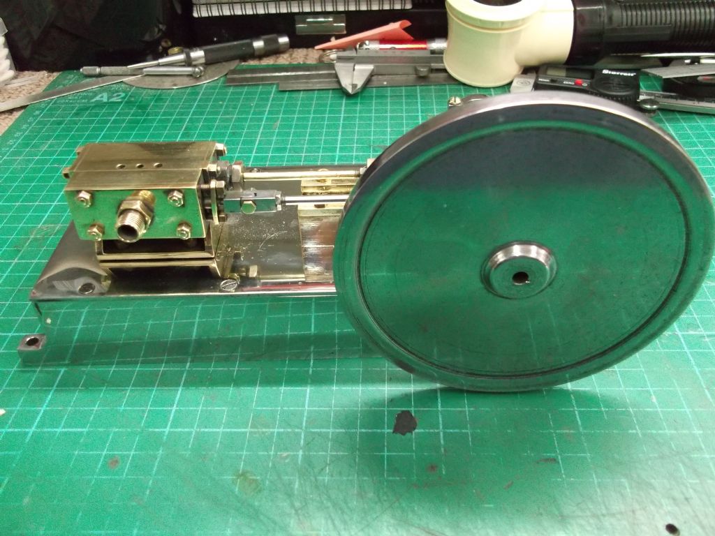
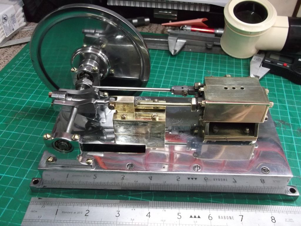
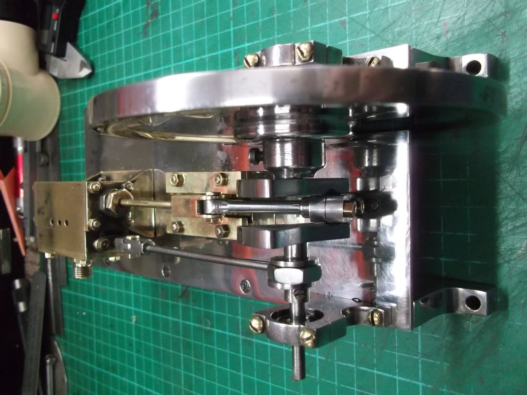
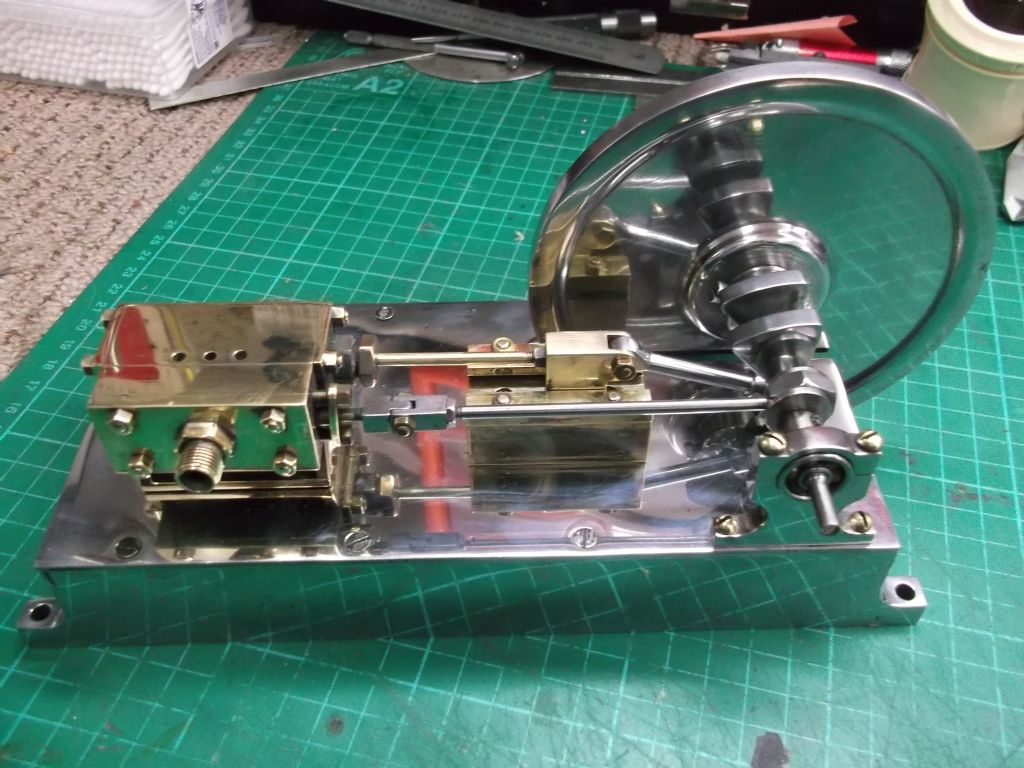
      dscf0004.jpgdscf0002.jpgHere is a recent addition. Does anyone have any information on it I wonder.

      The shaft runs in ball bearings and the only marks that I can find on it are the No's 1 & 2 next to the shaft housings

      Regards to all

      John

      dscf0001.jpg

      Advert
      #3448
      John McCallum 1
      Participant
        @johnmccallum1
        #539472
        Mike Hurley
        Participant
          @mikehurley60381

          My initial thoughts are that it is a home-brew. Obviously someone has taken a lot of care in construction, but there are a few contradictions in its design. A single cylinder slide valve engine, if it was an atypical model of the type would normally have 1. A spoked flywheel 2. Plain bush main bearings.

          If someone has made this without castings, I personally would have still manually 'spoked' the flywheel from solid to better suit this type of engine. The length of the main shaft seems excessive considering it's diameter also, I would suspect it could be prone to bending. It's definately a bit of an odd ball, thats been built by someone with very good abilities.

          As a bit of a stationary steam egine buff myself, Will be most interested if anyone else comes up with more suggestions / info

          Regards Mike

          #539476
          JasonB
          Moderator
            @jasonb

            I have a feeling that skinny flywheel is meant to be mounted inboard and fit in the slotted base. That way a take off pulley where the flywheel is now situated would be better supported should you want to drive something with it.

            As Mike says bit of a homebrew rather than a recognised design

            #539477
            Nigel Graham 2
            Participant
              @nigelgraham2

              Regarding the flywheel, while they were normally spoked, those on faster-running engines were sometimes faced with timber or sheet-metal to reduce noise and draughts. Though that was likely to have been a customer's modification, perhaps this engine's builder was inspired by an example of that practice.

              I can see why the shaft is extended as it is, to carry the pulley(s) – the slot in the base is the clue to that – but yes, there should be a bearing adjacent to the crank-web.

              #539510
              roy entwistle
              Participant
                @royentwistle24699

                I don't like the use of slotted screws where they should be studs and nuts

                Roy cheeky

                #539513
                Dave Halford
                Participant
                  @davehalford22513

                  It's possible that the flywheel whipped a bit too much in the designed position due to the skinny crank and long unsupported length the real answer might be another main bearing.

                  If the flywheel was spoked would it still be heavy enough to allow low revs?

                  #539533
                  MichaelR
                  Participant
                    @michaelr

                    Of all the points made about the engines construction has any one noticed the eccentric strap which seems to be made from a hexagon nut and not split, so is the sheave in two pieces ?

                    I like that engine it's different.

                    Mike.

                    #539536
                    JasonB
                    Moderator
                      @jasonb

                      If you look closely you cab see there is a boss either side of the eccentric by the larger diameters than the crankshaft and look closer still at the reflection in the base and you can see the slotted grub screw in the inner boss ( top photo). I would think one half is flange and eccentric the other just a flange to keep the strap in place.

                      Not seen another like that but have seen several where the flange on one side is fixed with a CSK screw to the side of the eccentric

                      Edited By JasonB on 13/04/2021 14:30:05

                      #539552
                      MichaelR
                      Participant
                        @michaelr

                        Jason, Now that I have looked closer I think you are right saves having to split the strap.

                        Mike.

                        #539619
                        Hopper
                        Participant
                          @hopper

                          Looks like the type of thing marine engineers used to make in engine-room workshops to while away the hours at sea, using whatever materials were at hand and designing from memory as they went. A form of folk art rather than a purist scale model of any specific prototype.

                          #539631
                          Nigel Graham 2
                          Participant
                            @nigelgraham2

                            "Folk art".. Yes, it could well be. None the worse for that, though. This engine might raise eyebrows with its slotted screws and ball-races, but it's a lovely object in its own right.

                            I know one model-engineer who built a beautiful (3"?) scale Allchin traction-engine, some of it while a diving officer on a RN mine-sweeper, where he obtained the Chief Engineer's permission to use the " tiffys' " workshop in his off-watch hours. He said that if the ship had been sent into action, his engine parts would have had to gone overboard along with the tinned food and the Captain's bicycle.

                            I once owned a curious little hand-rotated lathe made almost all in brass, and while not very practical for serious work it was intriguing. I'd found it in a second-hand shop, its history unknown. I wonder if that had been a "bunny".

                            Quite a lot of high-quality tools in circulation were apprentices' training-pieces, too, and sometimes bear the name or initials of their makers, and year of manufacture,, stamped on them.

                            #539643
                            John McCallum 1
                            Participant
                              @johnmccallum1

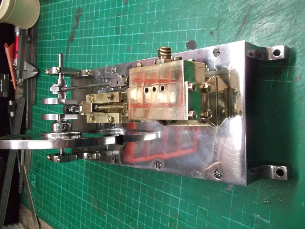
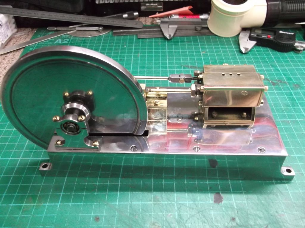
                              dscf0004.jpgdscf0003.jpgdscf0002.jpgThanks to all for your interesting and helpful replies. Not sure about " folk art " though!

                              Here are some photographs with the flywheel in its correct location.

                              Best to all

                              Johndscf0001.jpg

                              #539650
                              SillyOldDuffer
                              Moderator
                                @sillyoldduffer

                                The 'Mill Engine' design has been around a long time: it's very similar to the 1901 Thompstone Engine Jason is reinvigorating in ME at the moment. (Part 1 is in 4662.) Pretty much the same layout as Stewart Hart's PottyMill, and one of my old text-books describes a full-size engine of the same type. A sort of small simplified mill engine, no reverse, or condenser, slide valve driven by an eccentric, only a couple of HP, plain build, and presumably intended for a small enterprise mixing dough, making butter, driving a laundry or whatever. I believe the type was very common before electric motors took over, and they make good model – not too difficult in basic form for beginners, castings or fabricated, and can be made more elaborate if required. For example the PottyMill's plain Aluminium cylinder is mounted on a block, whereas Jason's Thompstone has turned brass feet inset into a Bronze cylinder with tasty decorative bands.

                                The polish and fine finish suggest the engine was made by someone who had plenty of spare time. The absence of spokes suggest he or she had access to a lathe, but not a milling machine, and perhaps decided to tackle them later. I agree the flywheel should be in the slot, which suggests the engine has been assembled incorrectly. Possibly someone made it, got it into running condition, and then passed the engine on to a new owner who beautified it, but didn't have the facilities to cut spokes, quite understand the flywheel, or realise the slotted-screws were temporary.

                                My first PottyMill is rough because I built it to exercise my weak machining skills: it wasn't intended for show, and the result is purely functional with many unfixed blemishes. Maybe when I'm dead it will be refurbished and sold in a glass case as an attractive antique, claimed to have been handmade by James Watt in 1760…

                                Dave

                                #539653
                                JasonB
                                Moderator
                                  @jasonb

                                  Looks a lot better now you have moved the flywheel to where I suggested smiley

                                Viewing 15 posts - 1 through 15 (of 15 total)
                                • Please log in to reply to this topic. Registering is free and easy using the links on the menu at the top of this page.

                                Advert

                                Latest Replies

                                Home Forums Stationary engines Topics

                                Viewing 25 topics - 1 through 25 (of 25 total)
                                Viewing 25 topics - 1 through 25 (of 25 total)

                                View full reply list.

                                Advert

                                Newsletter Sign-up