Posted by John Haine on 15/02/2022 09:37:10:
…
These sense resistors go in series with the motor and need to be matched to the motor power, which is why it's a plug-in component (though it probably gets hot too). I think these controllers keep the motor speed approximately constant by having in effect a negative output resistance which cancels out the motor's internal rotor resistance, so that the armature voltage is a good indication of speed. This resistor trims the output impedance by adding a small positive value to match the motor. The fact that it has blown up shows …
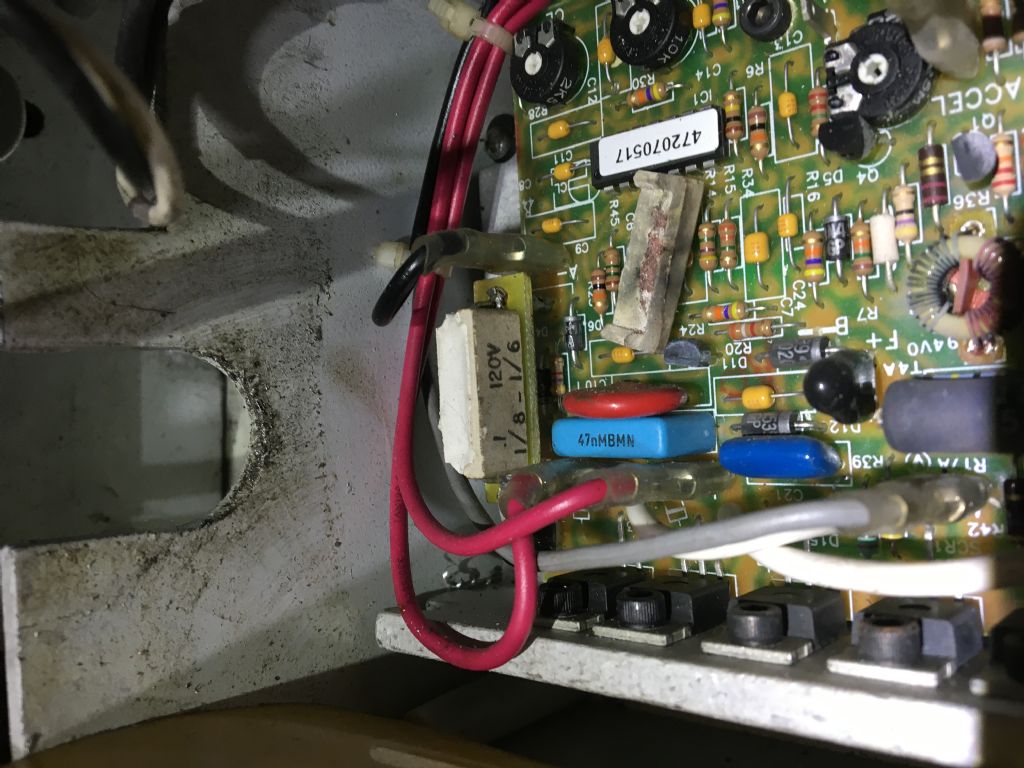
John answered the question while I was wondering what a 'Horsepower Resistor' was, for reference the remains are shown in Philip's photo below:

It's a 0.1Ω (may be sold as 100mΩ ) resistor, which are widely available in the UK from electronics suppliers such as RS. What I'm not clear of is the wattage.
Guestimating, assuming the motor is 250W (⅓HP) at 180V, maximum current (R) would be:
250/180= 1.4A and as W=I²R
1.4 x 1.4 x 0.1 = 0.2W dissipation.
Philip's resistor is labelled 120V and ⅙HP (125W), in which case:
125/120 = 1.25A and
1.25 x 1.25 x 0.1 = 0.16W dissipation.
On the face of it, a 0.1Ω 1W resistor would do the job (5x safety factor). But I'm wondering if the resistor is also used as a fuse, and the wattage should be lower because it's meant to run hot? I think the component might be dual-purposed as a fuse because it's lifted away from the board presumably to reduce damage, the resistor body looks like a flash catcher, and the pink spray of copper on the lid reminds me of a blown fuse.
Worth Philip trying a new 0.1Ω resistor but I fear the accident has damaged many components.
Dave
Edit: I hate smileys!
Edited By SillyOldDuffer on 15/02/2022 10:40:50
Steve Clark 1.


