Another Engine Build

Advert

Another Engine Build

Home Forums Stationary engines Another Engine Build

Viewing 24 posts - 76 through 99 (of 99 total)
  • Author
    Posts
  • #485706
    Ron Laden
    Participant
      @ronladen17547

      Thanks Jason, I am taking out of a piece of 1.75 inch square bar as I don't have any round large enough. Thought of putting a hole in for the boring head and centering it in the chuck on the RT. Then machining the outer rad and the flats then change over to clamping it on the flats and bore to the 20mm using the eccentric as a plug gauge. If I hold it via the flats I can probably stick with a 2.0 mm wall.

      Advert
      #485808
      Ron Laden
      Participant
        @ronladen17547

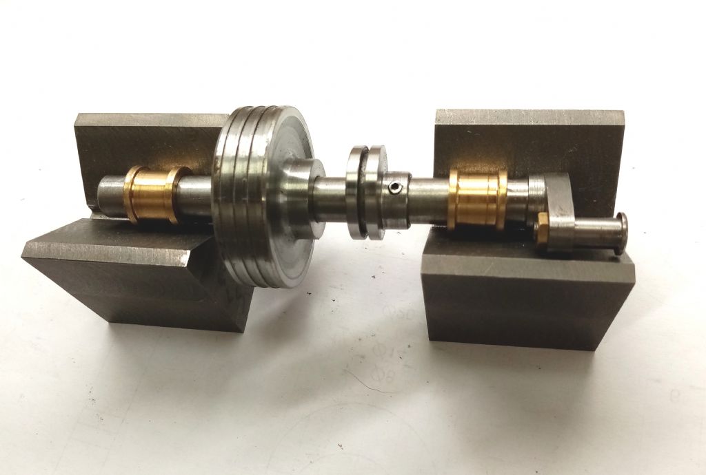
        Finished the eccentric though I may make it again, its not quite to the drawing and to be honest I found it a bit tricky to make, probably my inexperience. The good thing is its spot on dimension wise and a nice finish on the running face it just looks a tad different.

        img_20200715_150110.jpg

        #486370
        Ron Laden
        Participant
          @ronladen17547

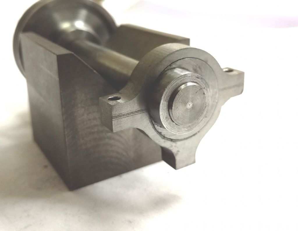
          Eccentric strap in cast iron it's the best I can do with it.

          The wall thickness is tad heavier than the drawing and I have left all 3 lugs at 6mm, pleased with the fit to the eccentric, should run well.

          img_20200718_062759.jpg

          #486375
          JasonB
          Moderator
            @jasonb

            That should do the job.

            Can't remember now but did you use a larger dia crankshaft as the boss for the eccentric looks thinner than mine?

            #486403
            Ron Laden
            Participant
              @ronladen17547

              Hi Jason, yes I had 10mm ground bar at the time and used that, probably a bad choice and should have turned it down to 8mm.

              As for the thin walled boss, Shhh… your not supposed to notice things like that, all I can say is blush blush​​​​​​. Anyway I have just sleeved it to 14mm which looks a bit better.

              img_20200718_101307.jpg

              #486651
              Ron Laden
              Participant
                @ronladen17547

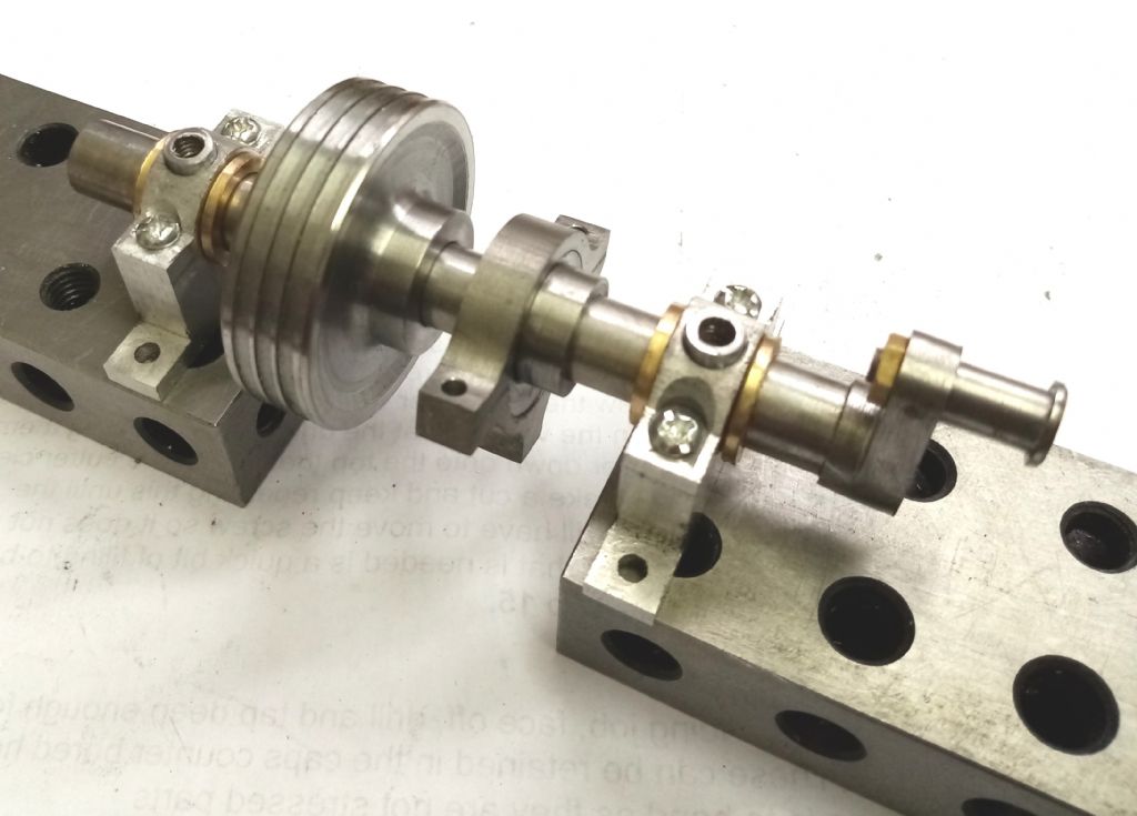
                Bearing pedestals done just need a debur and a clean up.

                img_20200720_064424.jpg

                #486659
                Ron Laden
                Participant
                  @ronladen17547

                  Morning Jason, just checking but are the piston and valve rod glands fitted with full nuts and then a locknut?

                  Ron

                  #486661
                  JasonB
                  Moderator
                    @jasonb

                    Yes

                    #487043
                    Ron Laden
                    Participant
                      @ronladen17547

                      Jason, the valve rod is centered in the valve chest 5mm from the cylinder face. Half the width of the valve nut is 2.3mm plus the 1.0mm step in the valve slot plus the 2mm thick valve face which totals 5.3mm.? am I missing something..?


                      Edited By Ron Laden on 22/07/2020 08:41:06

                      #487048
                      Ron Laden
                      Participant
                        @ronladen17547
                        Posted by Ron Laden on 22/07/2020 08:28:09:

                        Jason, the valve rod is centered in the valve chest 5mm from the cylinder face. Half the width of the valve nut is 2.3mm plus the 1.0mm step in the valve slot plus the 2mm thick valve face which totals 5.3mm.? am I missing something..?

                        Edited By Ron Laden on 22/07/2020 08:41:06

                        I am being dim this morning if I read the drawing correctly I would have seen the nut doesn't sit on the 1.0mm step but having said that I still can't see that the dims put the valve face to face with the cylinder..?

                        #487076
                        JasonB
                        Moderator
                          @jasonb

                          Ron, sounds like you have got your nut the wrong way round and are putting it into the slot for the rod, if assembled correctly there is room for the valve to lift off the surface.

                          rons nuts.jpg

                          #487142
                          Ron Laden
                          Participant
                            @ronladen17547

                            Hi Jason, I am in the process of finishing the valve parts and I am thinking of the parts fitting together as per your assy above so I think I have that correct. I was assuming that the valve would be a close face to face sliding fit with the cylinder with next to nothing in the way of any clearance, is that not the case..?

                            #487144
                            JasonB
                            Moderator
                              @jasonb
                              Posted by Ron Laden on 22/07/2020 08:28:09:

                              Half the width of the valve nut is 2.3mm plus the 1.0mm step in the valve slot plus the 2mm thick valve face which totals 5.3mm.? am I missing something..?

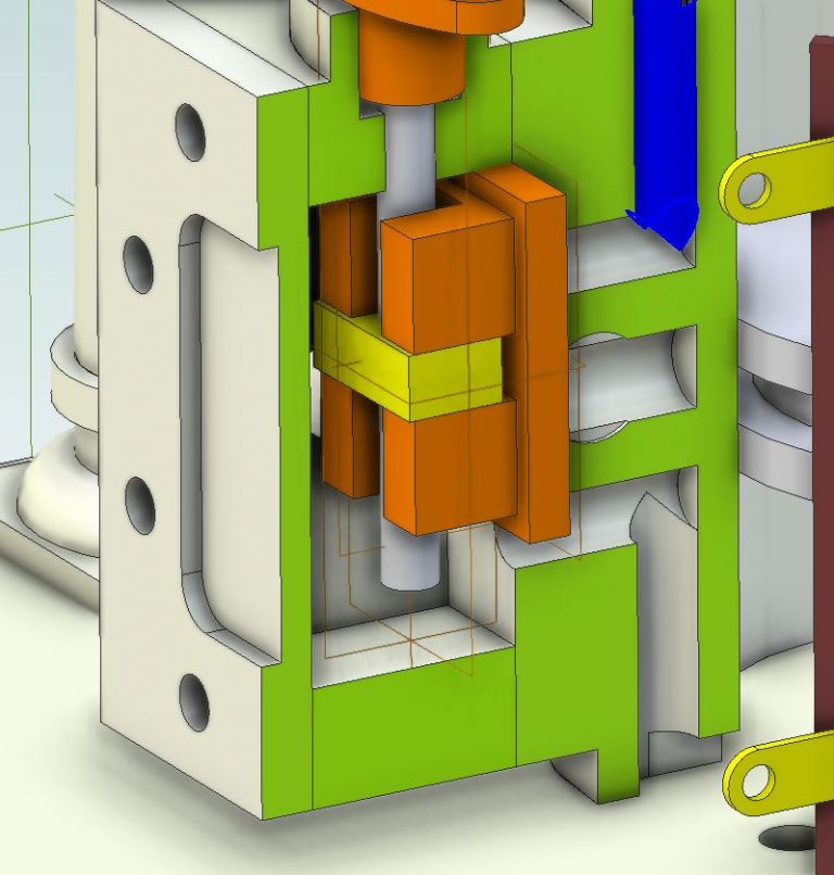
                              Ron, this is where you are going wrong, if you look at that sectioned drawing I posted earlier you will see that the 1mm step is at the bottom of the rod slot not the nut slot.

                              This means that the nut is free to move off the face by 0.7mm ( 5 – [2 + 2.3]). This ability of the valve to lift off the surface is usual on slide valve engines as it allows any condensate that may gather in the end of the cylinder to be pushed out by the piston rather than being trapped and causing a hydraulic lock. As this engine has no drain cocks it becomes a more desirable feature.

                              In operation the steam or air entering the valve chest will push the face of the valve against the port face this is why it is important to ensure the valve moves freely on the nut/rod so that it can take up it's own position though not so free that there is slack at the end of it's stroke.

                              #487146
                              Ron Laden
                              Participant
                                @ronladen17547

                                Thanks Jason, I did realise eventually blush that the 1mm step was at the bottom of the rod slot but I couldnt understand the 0.7mm movement but with your above explanation now I do, I had no idea it worked like that.

                                Ron

                                #542770
                                Ron Laden
                                Participant
                                  @ronladen17547

                                  The Class 22 is awaiting a track test (next track day in two weeks) so thought I had better catch up and make the last few small parts for the Muncaster.

                                  I made the valve this morning which seems to have turned out ok, Jasons drawing calls for bronze but not having any stock at the moment I went with free cutting brass in the hope it will be ok.

                                  The rod slot is 2.6 mm wide x 4.0 mm deep and the nearest cutter I have is a 2.0 mm HSS 2 flute uncoated, the top end speed of the mill is 2500 rpm and I was a bit concerned how it would cope running at less than half speed. However it was fine and turned out ok, I started with a couple of 0.25mm cuts then increased to 0.5 mm and it cut just fine as did the two side cuts of 0.3 mm to achieve the 2.6 mm.

                                  Valve and eccentric rods, the exhaust and a couple of oil cups will see the parts list complete.

                                  img_20210502_143640.jpg

                                  #542779
                                  JasonB
                                  Moderator
                                    @jasonb

                                    Not much to go now

                                    #543060
                                    Ron Laden
                                    Participant
                                      @ronladen17547

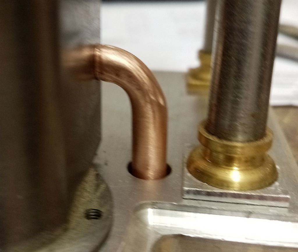
                                      No not much now Jason though I had forgotten the exhaust so I made that this morning. A bit of trial and error and a couple of failed attempts but got there in the end. I used some thick wall 1/4 o/d copper tube which I opened up to 4mm i/d. Clamped a 1/4 dowel to a block, heated the tube and formed it around the dowel. It did leave a slight flat on the outside of the bend but a smear of JB should cure that.

                                      img_20210504_101410.jpg

                                      #543296
                                      Ron Laden
                                      Participant
                                        @ronladen17547

                                        Oil cups made, they are a tad under size as I didn't have any 5mm hex brass only 3/16" hex so used that, should be ok.

                                        Just waiting for a M2.5 die to arrive so I can make the eccentric and valve rods.

                                        img_20210505_104923.jpg

                                        #543479
                                        Ron Laden
                                        Participant
                                          @ronladen17547

                                          Hi Jason

                                          I have a memory like a sieve can you please remind me of the UK supplier for the small head metric screws.

                                          Thanks

                                          Ron

                                          #543622
                                          Ron Laden
                                          Participant
                                            @ronladen17547
                                            Posted by Ron Laden on 06/05/2021 09:36:18:

                                            Hi Jason

                                            I have a memory like a sieve can you please remind me of the UK supplier for the small head metric screws.

                                            Thanks

                                            Ron

                                            Found it Jason, Polly models, does the German supplier carry a larger range than Polly?

                                            Ron

                                            #543623
                                            JasonB
                                            Moderator
                                              @jasonb

                                              Yes a much larger range. GHW

                                              Edited By JasonB on 07/05/2021 07:31:46

                                              #543643
                                              Ron Laden
                                              Participant
                                                @ronladen17547

                                                Thanks Jason

                                                Don't know if I am missing something but GHW only seem to list High Head Hex Steel M2.5 in one length 12mm, the ones I had from Polly were 15mm long.

                                                #543648
                                                JasonB
                                                Moderator
                                                  @jasonb

                                                  Don't tend to use the hex screws much preferring to use studs but thought Polly were the same, Knupher do other lengths but shorter. You are measuring thread length not O/A?

                                                  #544607
                                                  Ron Laden
                                                  Participant
                                                    @ronladen17547

                                                    Thanks Jason,

                                                    I will go with studs also.

                                                    I need to make a new eccentric had a mishap with the original this morning, I was going through all the parts checking them against the drawings and for fit with mating parts. I found the groove in the eccentric measured 1.35 and not 1.5mm, dont quite understand that. It was some time back that I made the part but I was pretty sure I used a 1.5mm parting blade but it certainly is undersize.

                                                    I set it up in the 4 jaw to widen the slot and took it steady (probably too steady) and the tool grabbed making a mess of it. I could repair it but thought it better and probably quicker to produce a replacement.

                                                    These things are sent to try us.

                                                  Viewing 24 posts - 76 through 99 (of 99 total)
                                                  • Please log in to reply to this topic. Registering is free and easy using the links on the menu at the top of this page.

                                                  Advert

                                                  Latest Replies

                                                  Home Forums Stationary engines Topics

                                                  Viewing 25 topics - 1 through 25 (of 25 total)
                                                  Viewing 25 topics - 1 through 25 (of 25 total)

                                                  View full reply list.

                                                  Advert

                                                  Newsletter Sign-up