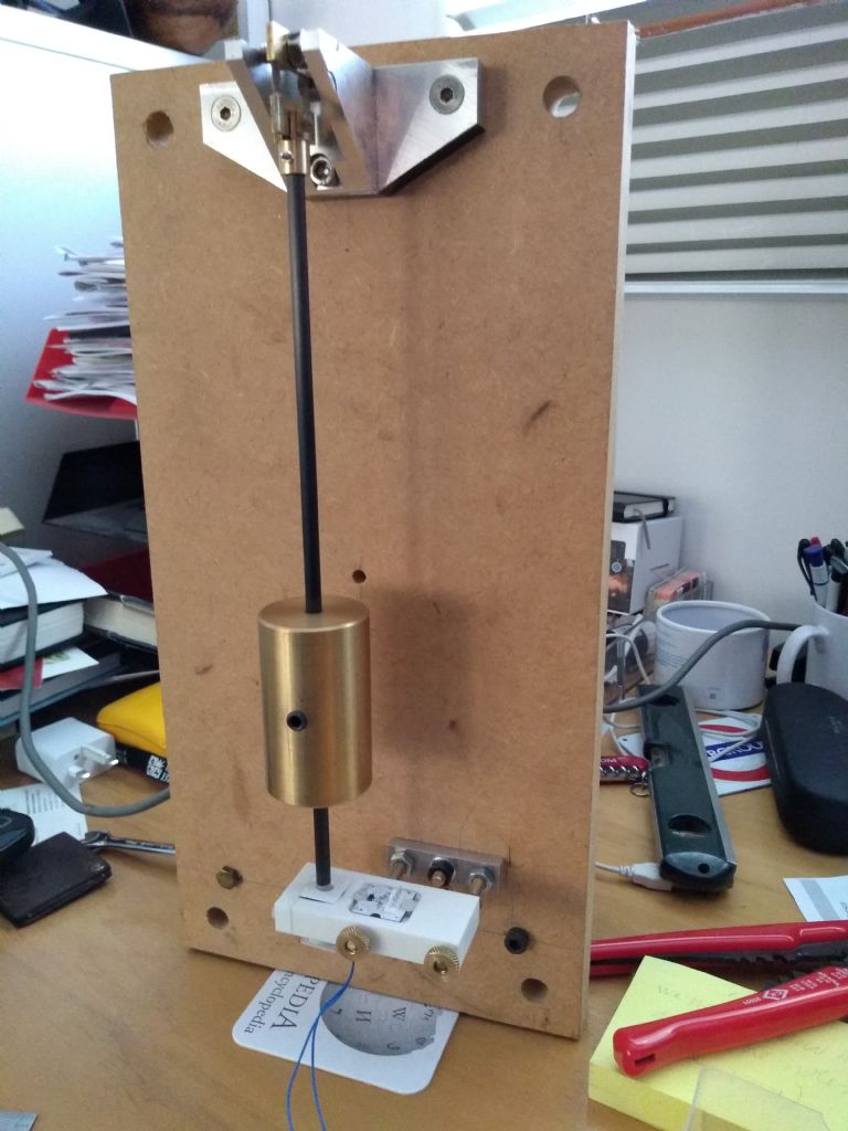
A while back I posted a couple of replies in the thread that SoD created on his experimental clock on something I was playing around with. I thought I'd create another thread with more details to avoid confusing Dave's thread. The photo shows the nearly complete clock which is now sitting on my desk keeping reasonable time. It doesn't actually lean over to the right, that's just the photo!
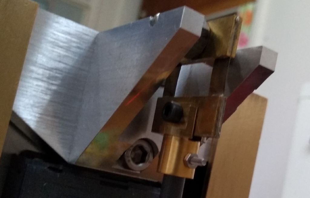
The pendulum is to the rear of the clock, suspended from a bracket mounted on two brass channel uprights. Also attached to these is the dial, a commercial dial plate from Meadows & Passmore mounted in a shallow tray CNC millied from 1/4 inch aluminium. Movement is a converted quartz, with the stepper coil disconnected from the IC and brought out on a couple of thin wires. Arduino Nano is mounted on a small bit of perf board on spacers from the plate below the dial. Pendulum rod (bit of 6 mm CF tube) suspended from double spring, brass bob about 75mm long clamped by set screw from behind. 12 x 3 mm Neo magnet in the end of the tube.

This is the back view of the former lash-up. The white block at the bottom has the impulse coil directly below the centre position of the pendulum, and a Hall effect sensor to the right that detects the magnet on its swing extreme to control amplitude. The block is now mounted slightly differently with adjustable height from the aluminium base.
I was very much using bits from the scrap box in making this and focusing on getting it finished so not much "design" but I think it looks at least OK. Still need to polish up all the metalwork, hide the power cable (currently running off a USB lead to the Arduino) and make some sort of "dome" to keep the dust out. Also of course get it regulated!
I'll write another post about the software.
John Haine.


