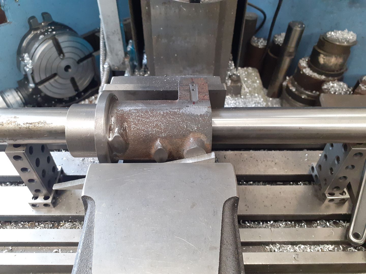
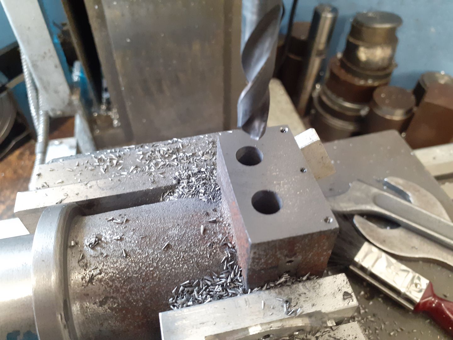
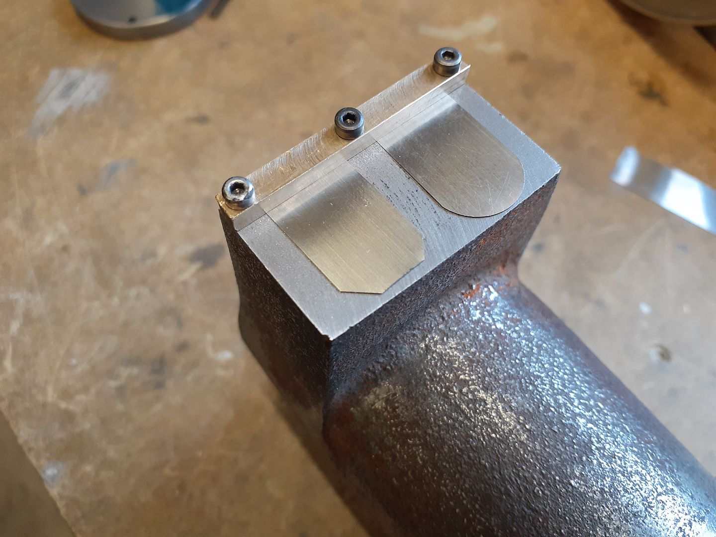
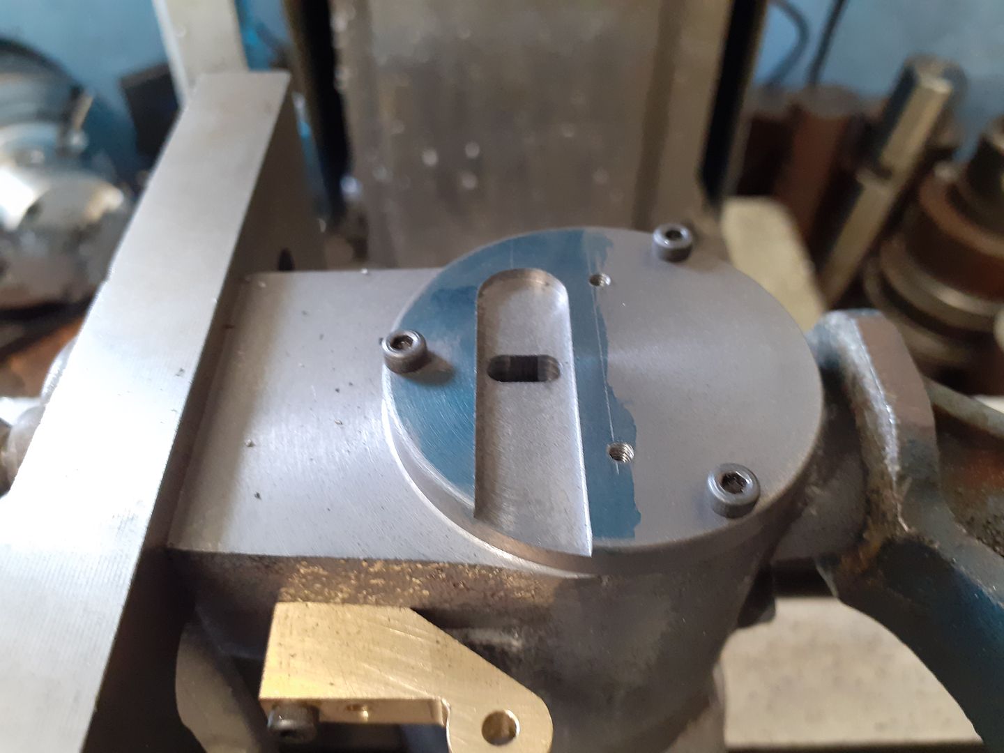
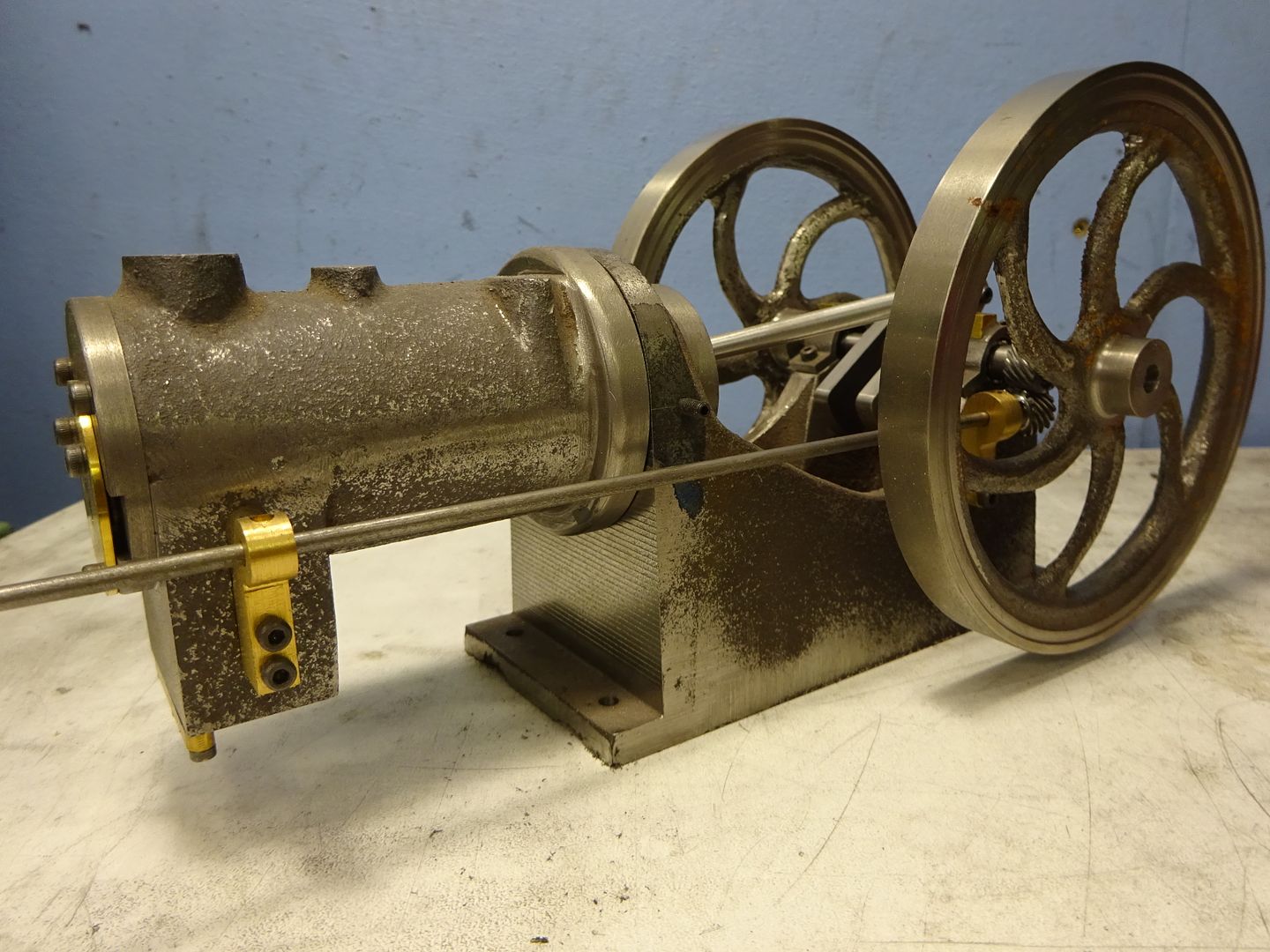
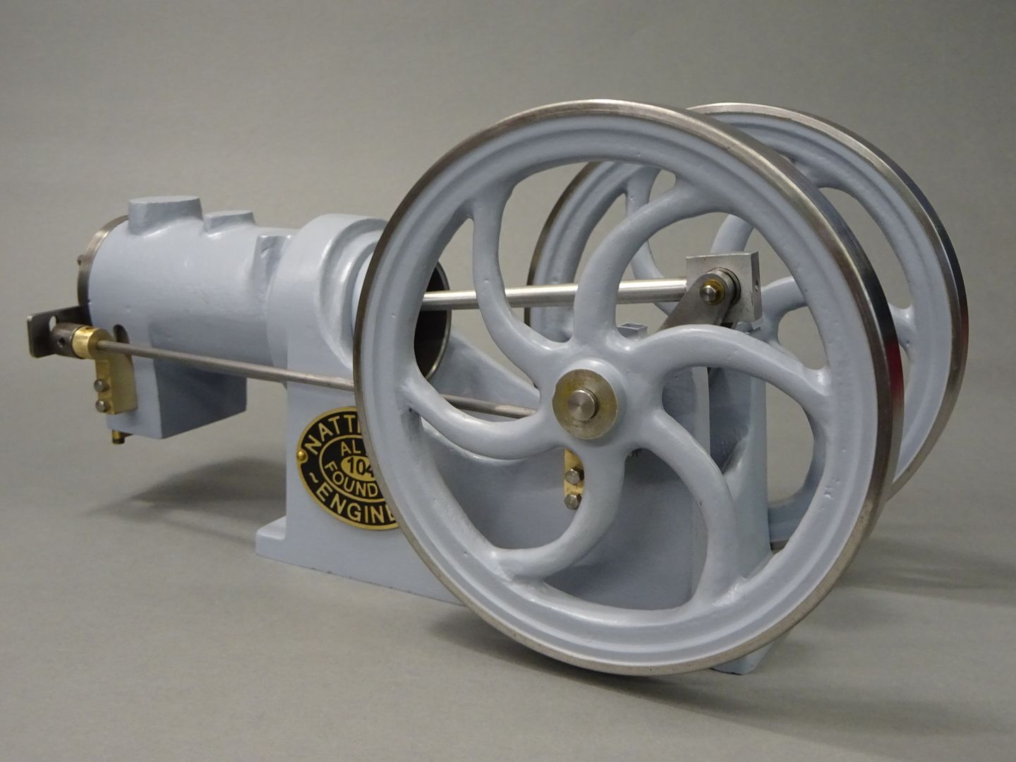
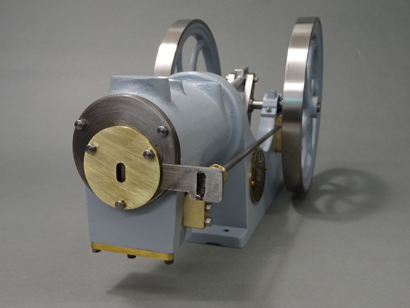
The head was turned from some CI bar and then screwed onto the cylinder so that the slot for the shutter could be milled in the right orientation. The other two holes together with teh bottom one of the three head studs are to hold a brass disc that retains the shutter in it's slot.

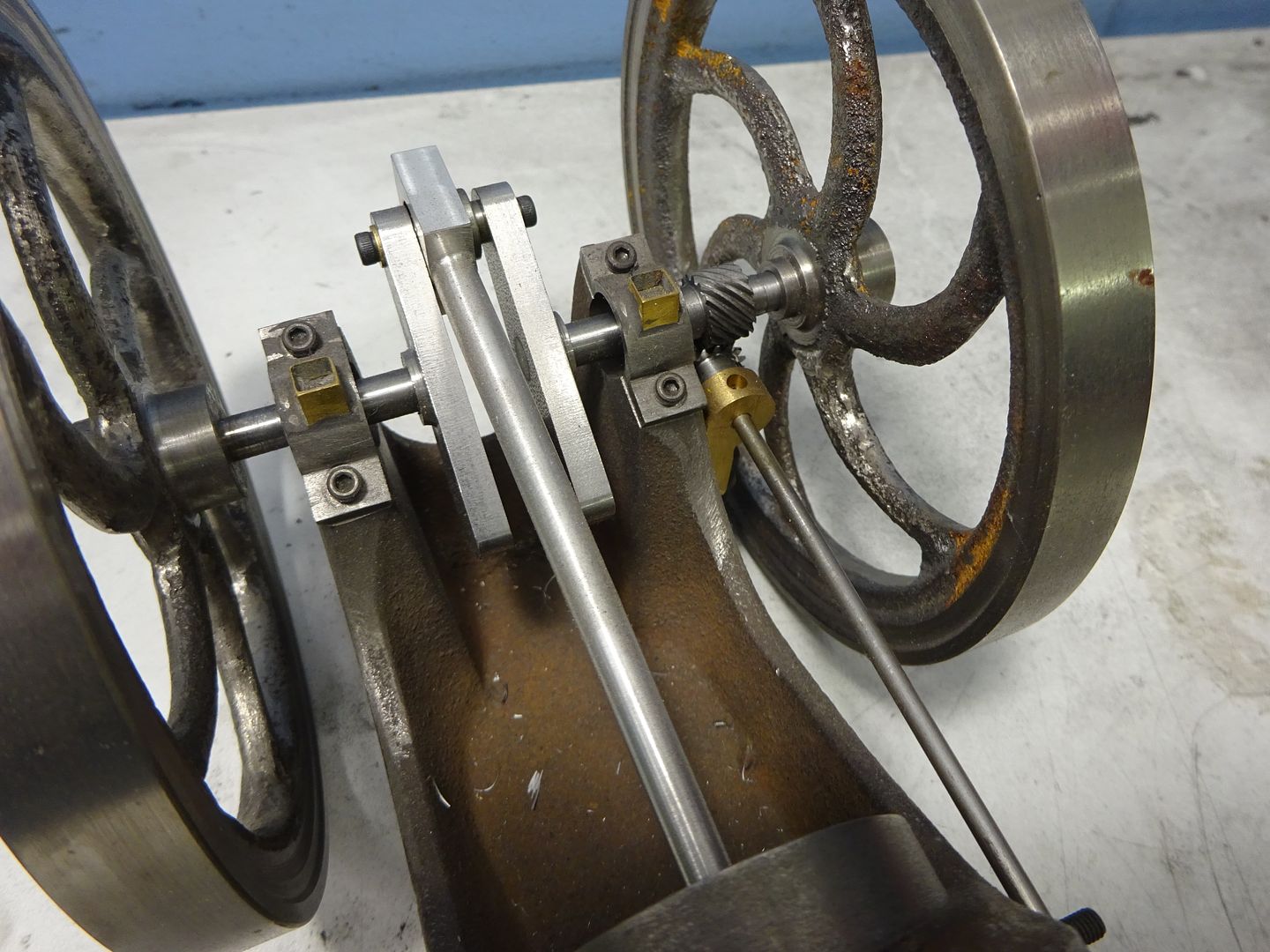
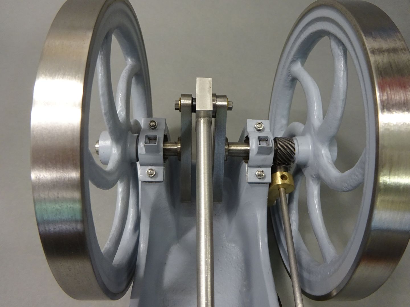
As Graham suggests using ball races on the conrod's big end that means the crankshaft can't be solid. I made the two webs and Loctited them to the half length shafts and then turned up the pin with spigots each end to locate in the crank web throws, the ends were also drilled and tapped for M3 bolts which hold the 3 parts together.

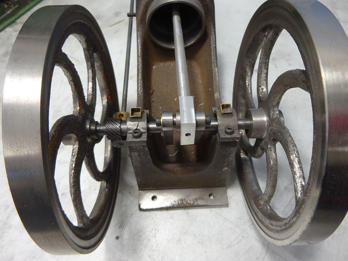
In this view from the front you can see the tops of the bearing caps have now been profiled and I also added some dummy oil boxes from 1/4" square brass tube.
To the left is the side shaft with one of it's brass supports and the helical gear, the pair of which came from GHW in Germany.

Here you can see the rear side shaft support and the shutter retaining disc in place.

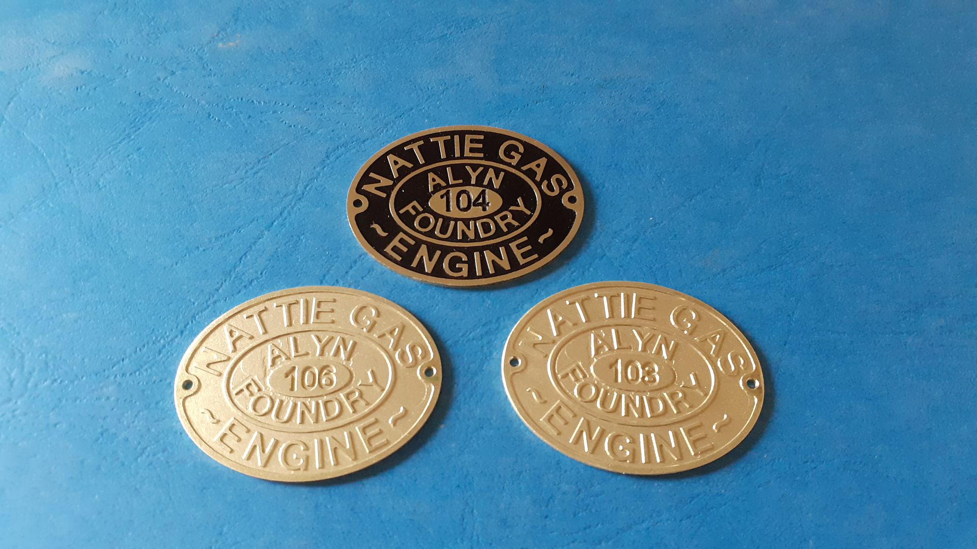
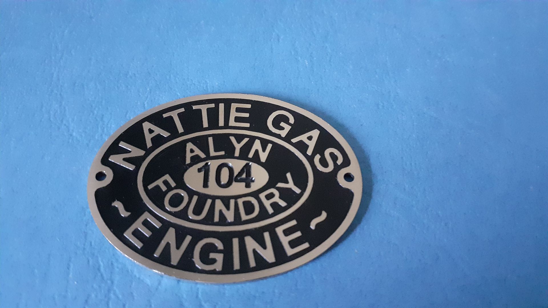
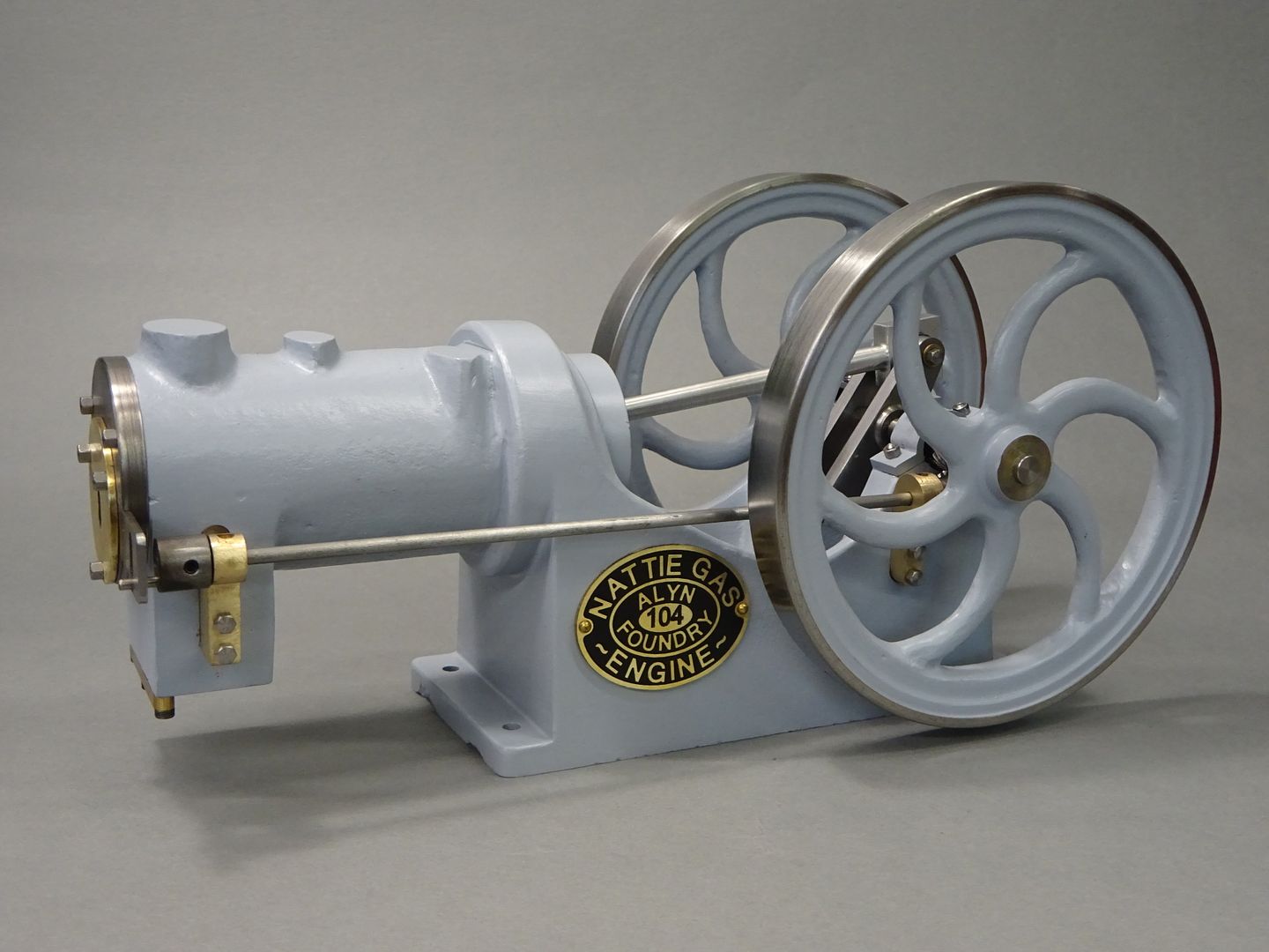
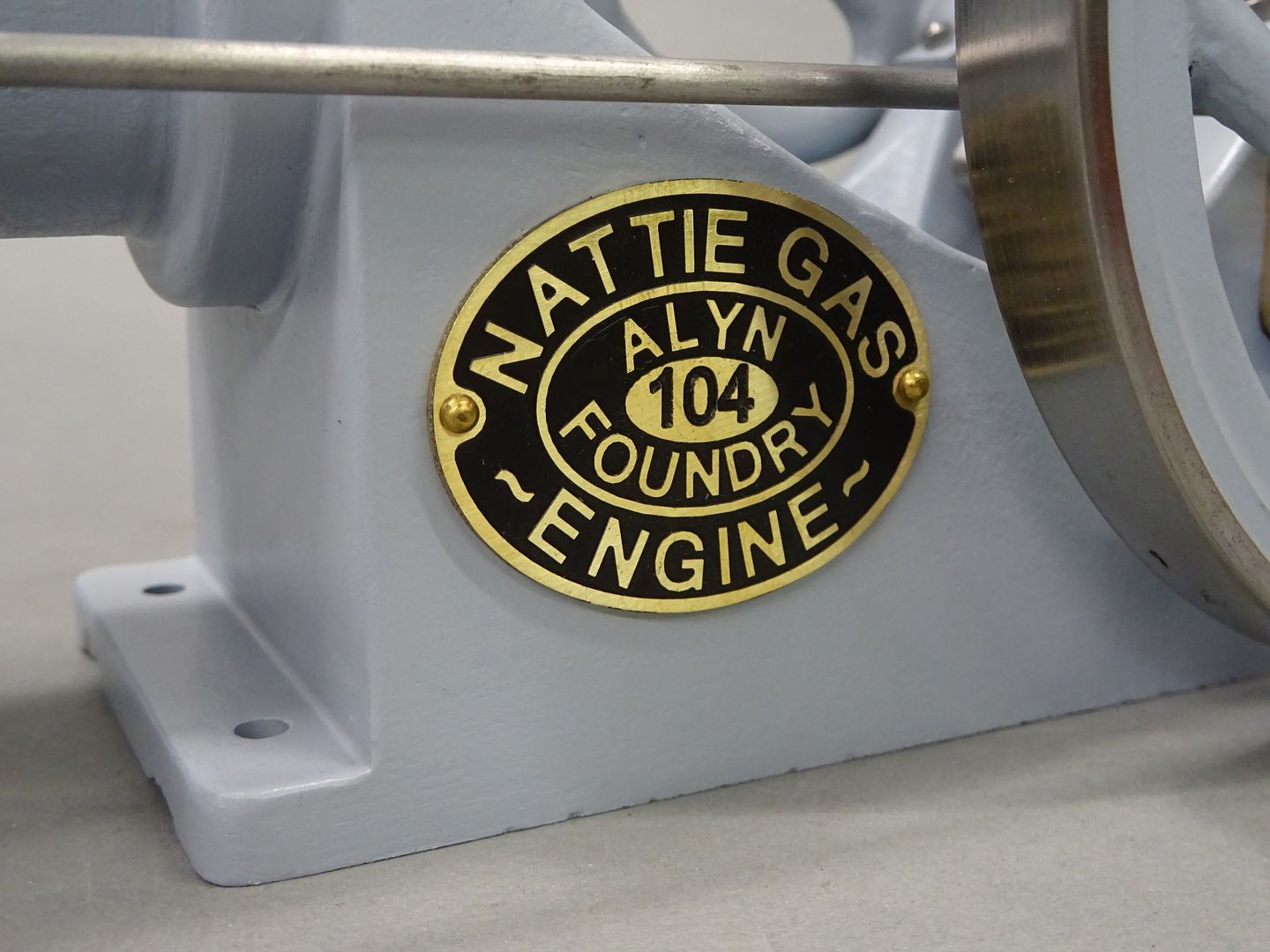
As this engine is new Graham did not have nameplates available and did look into having them laser engraved but I ended up doing a small batch for the small and exclusive number that exist. These were engraved and cut out on the CNC, the builder can infill with paint colour of their choice or leave bare brass.


Talking of paint I decided to go with a light grey on this one, at first I thought it may be too light but it has grown on me. It is actually Upol Acid8 primer with a clear sating over the top.


I've not made a dedicated burner for this one, I'll just have to get the blowtorch out when I want to give it a run
Could not help thinking while I was running this that it would be fun to see if the cylinder could be sleeved to form a water jacket, gears changed to get 1:2 ratio, add a couple of valves into what was the exhaust block (turned on it's side) and a spark plug or hot tube in the head, about 24mm bore should work.
 JasonB.

