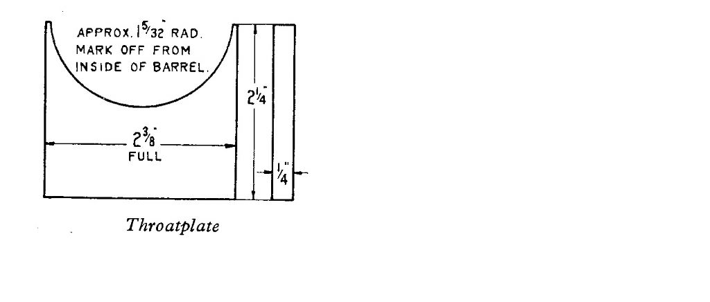
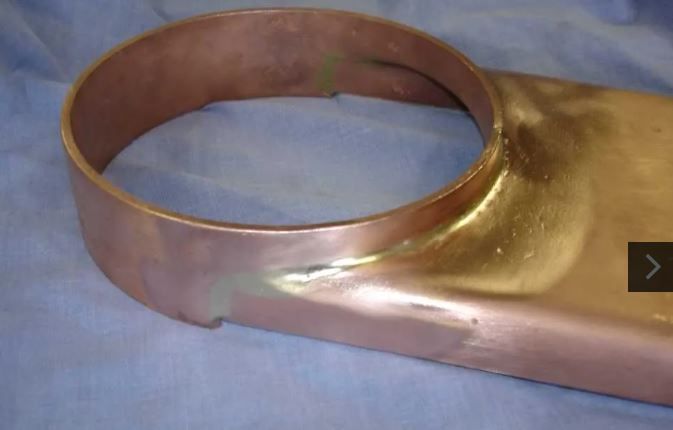
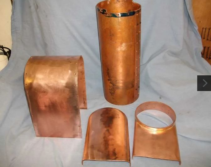
The Allchin barrel is made from a short piece of tube joined to a wrapped sheet that goes over the firebox. Figure 2.1 in the book shows the join between these two pieces. What I don't understand is that the throatplate just touches the underside of the barrel and is soldered there. There is no folded flange going inside the barrel to make a decent area to solder. The drawing just shows a line join between the throatplate and barrel.
I have done a search of the forum and can find no mention of this.
The figure 2.1 also shows the waisting of the firebox wrapper which is far more than the 1/32" on the drawing.
As far as I can see the throatplate needs flanging on the sides backwards into the firebox and forwards into the barrel. This makes for an interesting shape to the copper where the backwards flange meets up with the forwards flange. Must be possible, I imagine all loco type boilers have this double bend at this point, but can't find a photo of one in my limited collection of books.
The point is that at two points one either side, there seems to be a pinhole gap in the flange where it touches the wrapper and barrel. It also seems to be impossible to reinforce this point with some copper.
This raises the question that is 13SWG copper sufficiently strong that if this pin hole leaks then the copper has sufficient strength not to tear and cause the boiler to fail? I can find no intelligible information about how strong copper is in tension. If you had the 100PSI steam in the boiler and drilled a hole in the shell, would the steam just rush out or would the boiler explode? Is the tensile strength of the copper greater than the tearing force from the steam? What size hole would there have to be before the steam exceeded the strength of the copper?
Why wasn't the boiler made with the barrel split and folded down? But this also raises the question that the sides would need to be extended by a small amount. Instructions for other boilers say to rivet these extensions then solder. But again there are now four places where this strap butts up against the flanges at the front throatplate and rear backhead. Is this another source of weakness?
Reading scientific how to books (Materials and Techniques for Electron Tubes by Kohl) where they use silver soldering and the gap between the two pieces is given as 0.0015" to 0.010" (p382). This is not very much after walloping the copper to flange it. Ok, can clean up the front tube plate on a lathe, but all the others are just filed, 0.010" is a scratch. The scientific book specifically mentions solder dams where it can't flow past a scratch in the joint.
For example the wrapper side extension pieces. Do you put some flux in the between the side pieces and the reinforcing strap before riveting. Then what happens when it is heated up, has the flux dried? Is it hard and holding the pieces apart? Is assuming the flux will get inside the joint by placing on and around good enough? How do you know any solder has actually gone inside the joint? Don't forget we are looking at just 0.010" gap here.
The join between the barrel wrapper is made with a piece of 5/8" strip copper, this is 5/16" on each surface. Where is there any figures for the shear strength of copper and soldered joints that this is adequate. With the stresses on this joint from the model moving then this is needed? The steam pressure on this joint at 100PSI is 1104 pounds, or nearly 1000psi tensile.
Does this need to be addressed? Is is a problem? Tilting at windmills?
Bob Worsley.


