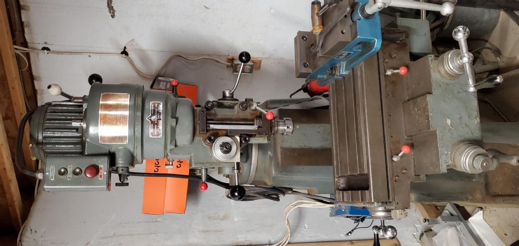
All things Beaver Mill

Advert

All things Beaver Mill

Home Forums Manual machine tools All things Beaver Mill

Viewing 25 posts - 151 through 175 (of 192 total)
  • Author
    Posts
  • #583989
    Mark Rand
    Participant
      @markrand96270

      Do you mean the bar or the nut?

      If you mean the bar, I've got some bits of CI that I could probably let go of, but getting it direct might be more simple.

      If you mean the nut, the problems with it are that the outside is undersize, which is why it's a 'spare' and there is only one half of the complete pair that is needed, so you'd have a fixed nut which didn't fit the casting it goes into and still have to make the adjustable nut that screws into it.

      Whereabouts are you based?

      Advert
      #584689
      Harold Jolly
      Participant
        @haroldjolly73409

        Hi it Harold . Asking about nut for the mill . I live in the united states . what is the out side diameter of the nut ? And the length.

        #584729
        Peter_H
        Participant
          @peter_h

          What may be more practical, and benefit everybody, is if Mark could post the drawing or whatever sketches he used for making it.

          It doesn't look much more than a cylinder with two different diameter bores, one fine threaded ( to mount it?) and the other threaded ACME for the lead-screw. Any external keys or flanges or anything Mark?

          "ekpsupplies2009"  at ebay.co.uk sells Meehanite 250 grade cast iron bar by the inch. 60mm diameter is around 4 to 5 ukp per inch(!) but is looks like the genuine article.  "southweststeam1" has 80mm bar at around £10 per inch. Any decent metal suppliers should be able to sell it but you'll be looking at buying a few meters minimum.

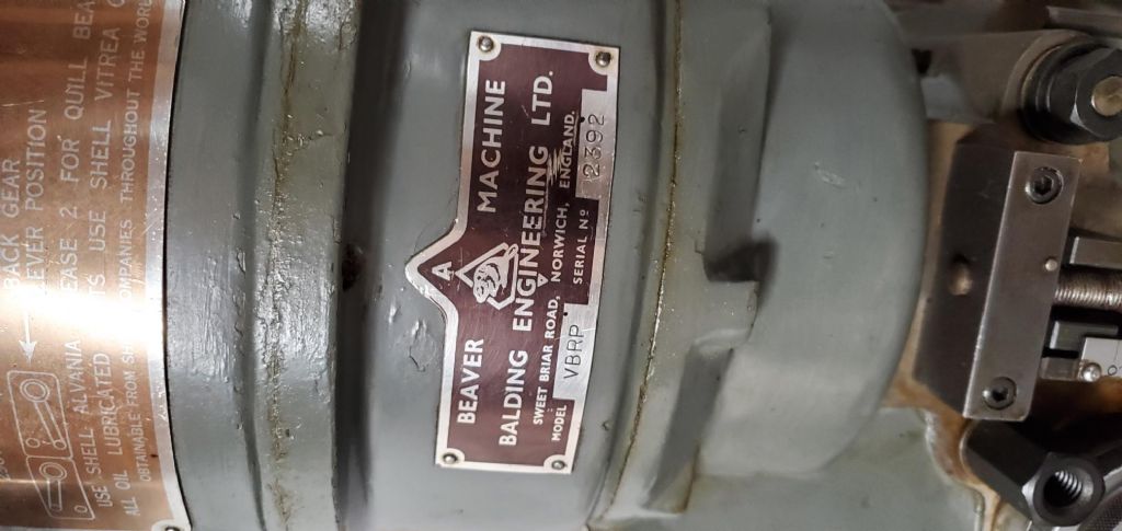
          In nearly 20 years on ebay, with Balding, beaver, VBRP as search terms, I have *never* seen a cross-feed nut for sale. What I do have somewhere is a balls-crew and nut for both full length table and cross-feed from a CNC version of the Beaver, but the end fittings are quite likely different.

          Peter


          Edited By Peter_H on 09/02/2022 10:34:58

          Edited By Peter_H on 09/02/2022 10:36:11

          #584824
          Harold Jolly
          Participant
            @haroldjolly73409

            Peter . Do you want to sale them ?

            #585346
            Mark Rand
            Participant
              @markrand96270

              it should be 1 5/8 outside diameter by 2 1/8" long. with 1 1/8" of 1" x5tpi ACME thread at one end and and 1" of 1.4"x 20tpi (or thereabouts) thread at the other end.

              There is a seat for a locating screw, but that it best drilled using the hole in the mounting bracket as a guide to get it in the right place.

              The matching half of the adjustable feed nut has just got a flange for holes a hook/C spanner can turn it with, a 20tpi thread matching the first part (exact diameters are irrelevant just make them to fit each other), and a 1" x 5tpi ACME thread.

              There is another collar that fits the external 20tpi thread of the second hald of the pair, that's for locking it in place after adjusting the backlash.

              Basically, this is what Harold's photos show. the best method is to make a set that matches the originals, using their dimensions as a template.

              The only part of the operation that isn't trivial is getting a 1" x 5tpi internal threading tool. I used a bit of 1/4" square HSS ground to the right form and held in an old boring bar.

              If one isn't comfortable with that, Carmex make a good tool that will do the job. Unfortunately the normal laydown threading inserts are a waste of space, since 5tpi ACME is a 22mm insert, which is too large to fit in the bore that's being threaded (like most bl**dy internal laydown inserts).

              #585391
              Peter_H
              Participant
                @peter_h

                Good description Mark, thanks.

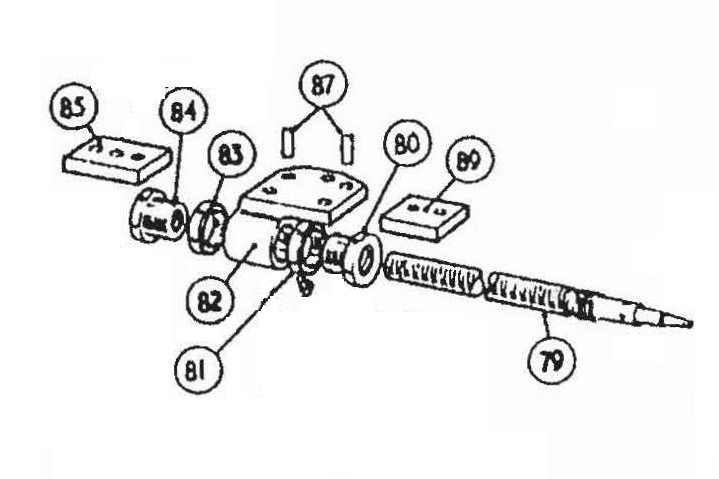
                It looks like the VBRP mk II was different. Both parts of the adjustable nut are the same or very similar, and consist of a normal 20tpi thread on the outside, a flange with C-spanner holes on one end, and 5 tpi ACME right through the middle. There a locknut each end similar to the flanges above, but with an internal 20tpi thread to screw on the outside of each nut half. So the nut halfs 80 and 84 screw into the fixed casting 82, adjusted by screwing each nut half lightly together, then locking with locknuts 83 and 81. The inside of the leadscrew hole in casting 84 leaves a volume that acts as an oil reservoir. You can just see the oil nipple near the right lock nut and adjacent to the item 84 leader line.

                beaver mk2 part 2 opt_page_38_crossfeed_screw_nut_mod.jpg

                #585497
                Mark Rand
                Participant
                  @markrand96270

                  That's a drawing of the Y feed, which has, as you say, got two identical movable bits. The X feed has only got the one movable bit, on account of not being able to reach inside the saddle to get at the other side of the assembly. laugh

                  #585522
                  Harold Jolly
                  Participant
                    @haroldjolly73409

                    20220213_155215.jpg20220213_155244.jpgi

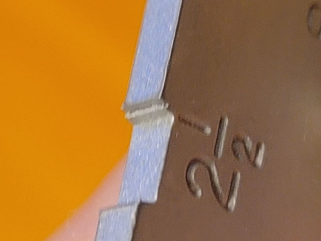
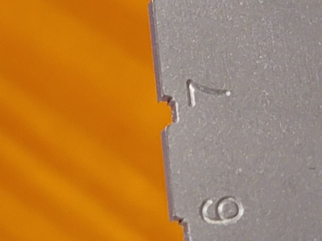
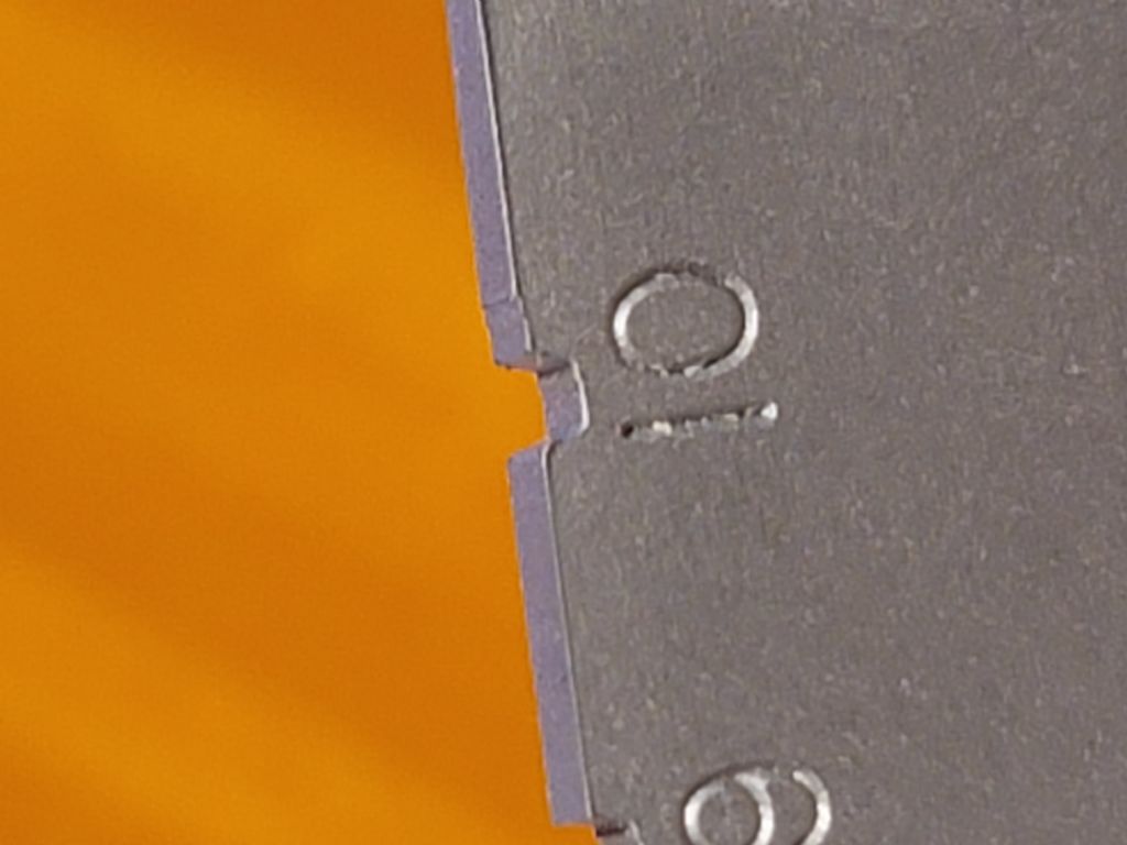
                    i bought this Mitutoyo tool gauge . Some of the notch are not at 29 % . should I send it back ?20220213_155256.jpg

                    20220214_165134.jpg

                    #585574
                    Peter_H
                    Participant
                      @peter_h

                      Mark – yes, the crossfeed nut. That's what I thought we were talking about? Having looked back at the original post I can see I grabbed the wrong end of the stick!


                      Peter


                      Edited By Peter_H on 15/02/2022 09:57:18

                      #598407
                      David MIller 10
                      Participant
                        @davidmiller10

                        I have a Beaver VBRP MK2 with a 5/8 UNC drawbar & are unable to remove this as I wish to replace with a 16mm

                        as this will be easier for tooling, can anyone give me an idea for withdrawal ?

                        #598428
                        Mark Rand
                        Participant
                          @markrand96270

                          You should be able to just pull it out of the top of the spindle after unscrewing from the tool.

                          Is it set up as a 'self ejecting' drawbar? If so, there may be a collar screwed onto the top of the spindle that would need removing.

                          #598440
                          bernard towers
                          Participant
                            @bernardtowers37738

                            That gauge looks unfinished, I have the brown & Sharpe version that must be about 60 years old and it is a joy to use all the sizes are beautifully ground. Is it possible its hooky?

                            #602432
                            Peter_H
                            Participant
                              @peter_h

                              If your ceiling is high enough to be able to pull the drawbar straight out the top then you're luckier than me!. Only way is to tilt the head right, do whatever with the drawbar, tilt it back and align it. Pain in the neck which I haven't had to do for about 125 years luckily.

                              #602445
                              Mark Rand
                              Participant
                                @markrand96270

                                Need a ventilation cowl on the roof, just above the spindle. laugh

                                #602578
                                Bob Unitt 1
                                Participant
                                  @bobunitt1
                                  Posted by Peter_H on 20/06/2022 10:33:39:

                                  If your ceiling is high enough to be able to pull the drawbar straight out the top then you're luckier than me!. Only way is to tilt the head right, do whatever with the drawbar, tilt it back and align it. Pain in the neck which I haven't had to do for about 125 years luckily.

                                  I had a similar problem with my Myford VM-B drawbar, which hit the ceiling of my workshop. It was in a two-storey structure with a bedroom above. I cut a square hole in the workshop ceiling plasterboard, glued in a short piece of square drainpipe abutting the floorboard above, and cleaned out the insulation material in the gap. This gave me room to remove the drawbar with about 1/2" to spare.

                                  #615929
                                  Ian Bowers
                                  Participant
                                    @ianbowers85137

                                    Hi,

                                    I was looking for different feed change gears for my MK1 VBRP as I only had the 48 32 combination and after finding them in the HPC gears catalogue I did a bit more searching and found the Myford ML 7 gears fit, even the hole size and keyway are correct, the only difference is they don’t have a boss like the originals so I just made up a couple of washers.

                                    I got a 59 and a 21 from RDG and they work fine, the 59 looked like a Myford part but the 21 looked like a pattern part and the teeth needed a bit of filing.

                                    The good news is they are around £10 each and there are loads of sizes available

                                    ian

                                    #638411
                                    Daniel Roberge 1
                                    Participant
                                      @danielroberge1

                                      Hello

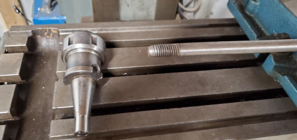
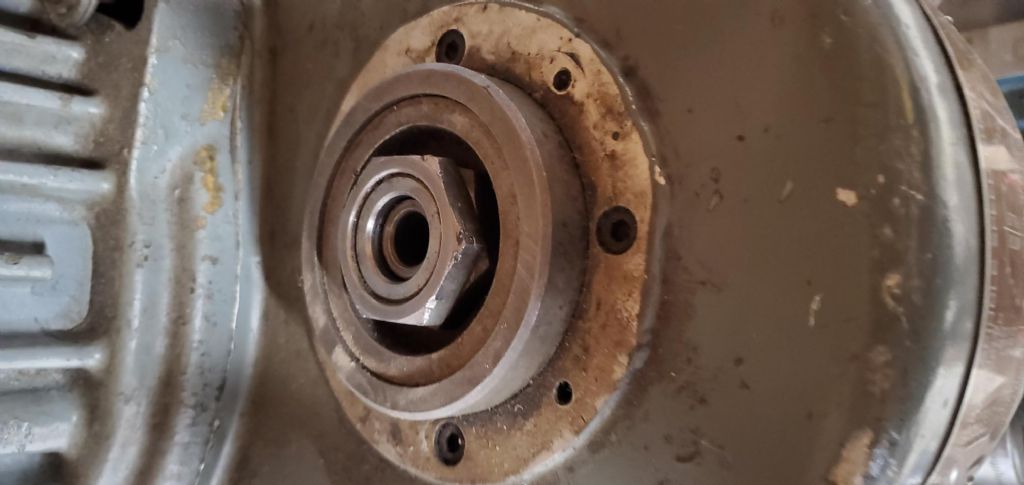
                                      New to the site as I've recently purchased a Beaver Mill. I would like to replace the draw bar on it as I suspect it is not original and also find it difficult to use when doing tool changes (haven't figured out if the spindle even locks and need to use a spanner wrench).

                                      Would anyone be willing to share some pictures of their draw bar / setup? Anyone install a pneumatic draw bar on their mill? Does that even work if I can't lock the spindle?

                                      Thanks.

                                      Daniel20230319_084430.jpg

                                      20230319_084437.jpg

                                      20230319_084517.jpg

                                      20230319_084527.jpg

                                      20230319_084542.jpg

                                      20230319_084605.jpg

                                      #638655
                                      Ian Bowers
                                      Participant
                                        @ianbowers85137

                                        Hi,

                                        I can have a look at my draw bar in the next day or so, I’m not sure if it’s original as I have spacers on it.

                                        There is no spindle lock I just use a low gear!

                                        Ian

                                        #638703
                                        Peter_H
                                        Participant
                                          @peter_h

                                          I'd be interested in any ideas for a pneumatic draw bar. Advancing years makes it more difficult to get up there with a spanner everytime.

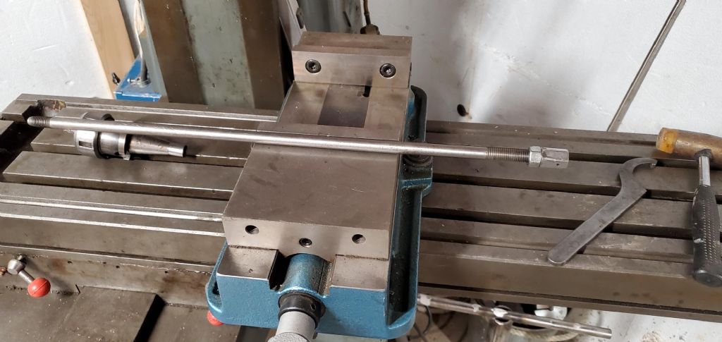
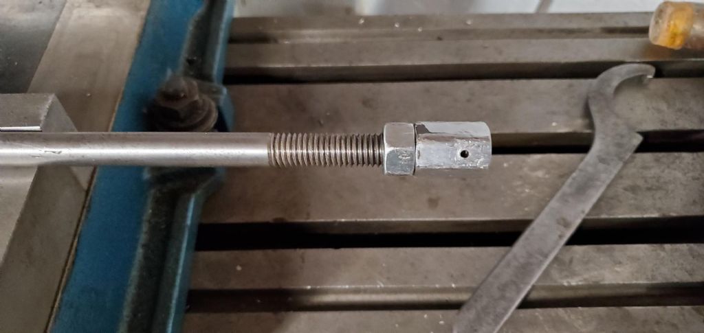
                                          Sorryu, due to ceiling height I can't remove the drawbar without tilting the head 90 degrees and it took an age to get in clocked in again last time. I made my drawbar from a simple length of steel M12 studding. I turned an over length brass nut with a taper on the bottom to keep it central when taking force, and a pair of locked together nuts for operating it. Surprising easy to get the length right. I don't have any INT30 holders with the old imperial drawbar thread, They're all M12.

                                          DItto as Ian, no spindle lock, just drop it into the low backgear. Fine for tightening chucks etc.

                                          #647723
                                          Lex Davis
                                          Participant
                                            @lexdavis38817

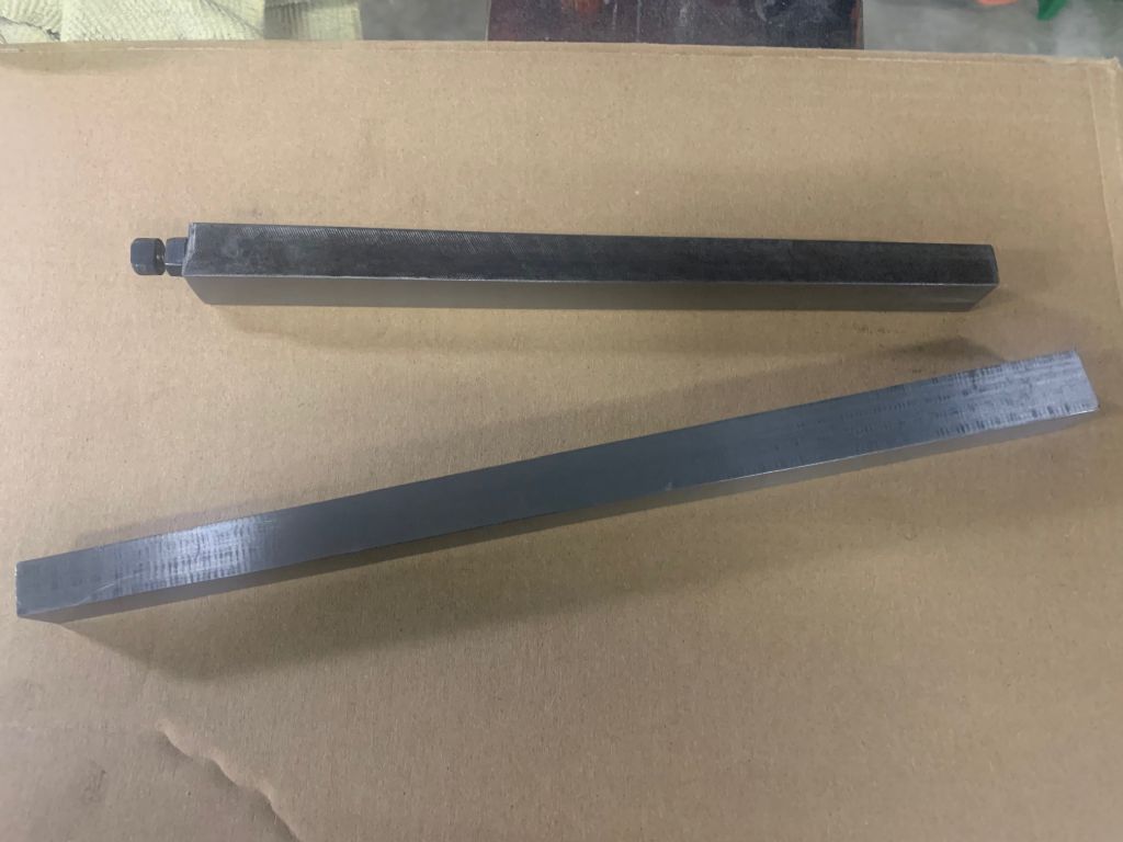
                                            Nearly four years ago I made some enquiries in this thread regarding the dimensions of the Y axis gib strip to allow me to make a new one and I finally got around to making it yesterday, I used a piece of flat cast iron bar and milled it to approximate size then ground it to fit. I will now finish the contact faces by scapping for a perfect fit and a bit of oil retention.

                                            The top one is the gib that was in the machine when I got it.

                                            img_5328.jpg

                                            #647736
                                            KWIL
                                            Participant
                                              @kwil

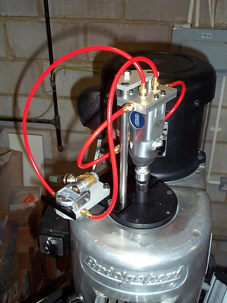
                                              I made and fitted a pneumatic drawbar for my Bridgeport, what with its riser and off floor pads, the top is quite high.

                                              Works every time without locking the spindle although I can if I wanted to.

                                              #647738
                                              KWIL
                                              Participant
                                                @kwil

                                                Air Power Drawbar

                                                Air Drawbar pic for Bridgeport

                                                #658361
                                                Lex Davis
                                                Participant
                                                  @lexdavis38817

                                                  My VBRP – 2 seems to have a lot of oil passing down through the spindle from the back gear housing, the diagrams in the parts manual are not very clear as to the sealing arrangement in there, has any one resealed one of these machines?

                                                  #658369
                                                  Nigel McBurney 1
                                                  Participant
                                                    @nigelmcburney1

                                                    I solved the drawbar removal problem on an Elliot turret mill when low ceiling height was a problem,I had a variety of 30 int tooling with different threads , so I made a new drawbar (en8)with a smaller diameter thread, and then plugged the threaded hole in the 30 int tooling and tapped them all to suit the new drawbar, some of the threaded inserts were more like helicoils but they worked with no problems and no need to remove drawbars,and were in use daily for around 25 years. This scheme was ok for 30 int but there could be potential problems if the spindle had been 40int.

                                                    #658381
                                                    Peter_H
                                                    Participant
                                                      @peter_h
                                                      Posted by Lex Davis on 29/08/2023 08:17:19:

                                                      My VBRP – 2 seems to have a lot of oil passing down through the spindle from the back gear housing, the diagrams in the parts manual are not very clear as to the sealing arrangement in there, has any one resealed one of these machines?

                                                      Lex, I did a clearer traced diagram of their exploded diagram of that area :

                                                      https://www.model-engineer.co.uk/wp-content/uploads/sites/4/images/member_albums/143475/808162.jpg

                                                      And of the casting alone :

                                                      https://www.model-engineer.co.uk/wp-content/uploads/sites/4/images/member_albums/143475/807977.jpg

                                                      In neither of them can I see any sign of an o-ring or flange seal, or any outlet other than the spindle/quill, but I'm unsure on orthogonal veiws. It looks like the only thing that stops spillage is the casting (green in dwg I think) being deeper than the back gear (dark blue in dwg), and the lower spindle seal (felt, hardens over the years, cracks apart when removed) leaks that spillage.

                                                      Obvious questions, but have you checked the oil sight guage on the front?. They are notorious for getting blocked with gunge and showing a fix incorrect reading. Over the years, the oil gets topped up and up and eventually over fill. Also, checked for casting cracks?

                                                      Maybe put a tin under the spindle, engage back gear and highest speed. Don something oil proof, stand well back, Quill up, push the startbutton, stop after 5 minutes, quill up, on for 5 minutes. Repeat. Or just pull the drain plug, change the sight guage, and refill.

                                                    Viewing 25 posts - 151 through 175 (of 192 total)
                                                    • Please log in to reply to this topic. Registering is free and easy using the links on the menu at the top of this page.

                                                    Advert

                                                    Latest Replies

                                                    Home Forums Manual machine tools Topics

                                                    Viewing 25 topics - 1 through 25 (of 25 total)
                                                    Viewing 25 topics - 1 through 25 (of 25 total)

                                                    View full reply list.

                                                    Advert

                                                    Newsletter Sign-up