All things Beaver Mill

Advert

All things Beaver Mill

Home Forums Manual machine tools All things Beaver Mill

Viewing 25 posts - 101 through 125 (of 192 total)
  • Author
    Posts
  • #491660
    Lex Davis
    Participant
      @lexdavis38817

      I didn't take much notice when I took the Quill assembly out Mark, but I did notice that there were burrs on the driven side of the splndle spline which I had to stone off. I have almost finished regrinding the spindle taper now so I will check the fit of the splines when I put it back together soon.

      Lex.

      Advert
      #491661
      DC31k
      Participant
        @dc31k
        Posted by Mark Rand on 20/08/2020 21:51:20:

        Has your's got noticable rotational play?

        As a 'for info.' for other owners, if you search around the terms 'Bridgeport splne noise' or 'Bridgeport spline knock' or similar, you can see solutions that people have come up with to address the problem.

        Generally they involve preloading the sliding male splines on the quill against the fixed female splines in the drive pulley. A Bridgeport is a bit different to a Beaver in that the male splines poke well up above the drive pulley when the quill is retracted.

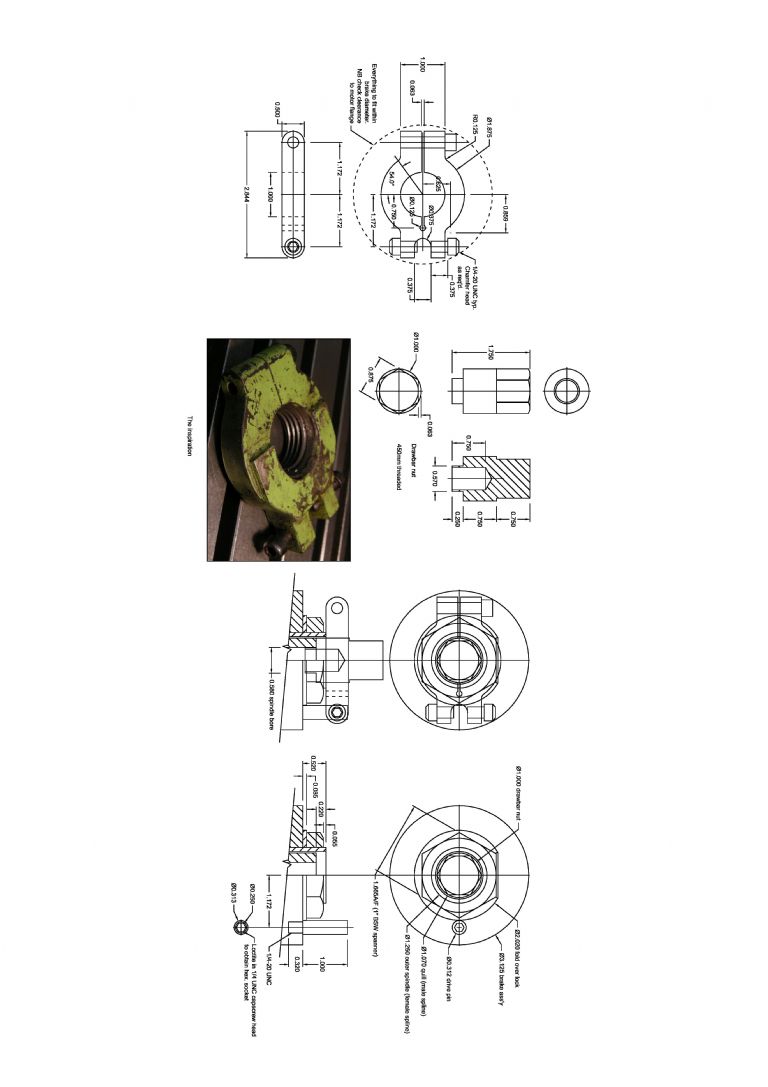
        On a PAL at least, the male splines are not visible so a slightly different approach might be needed. My head only really makes noise when flycutting or facemilling. Standard cutters are OK. See below for what I have made, noting that it does stop use of the quill when installed (but facemilling or flycutting with the quill sticking out is probably not a good idea anyway).

        beaver spline dog.jpg

        #492252
        Ian Bowers
        Participant
          @ianbowers85137

          Hi

          I too have a noisy VBRP mark 1 like Brian’s there was nothing between the bearings supporting the driven pulley, so I made a sleeve to allow me to tighten the pulley to the shaft. But I still have a metallic chattering noise which I think is from the coupling between the spindle and the pulley, should the dogs be tapered so there in no backlash? I also wondered if a stronger spring would help?

          Any more ideas out there?

          thanks Ian

          #492276
          Ian Bowers
          Participant
            @ianbowers85137

            One more thing should it have a spindle lock?

            Ian

            #492341
            Mark Rand
            Participant
              @markrand96270

              There was nothing between the bearing inner races of the driven pulley originally. A fitted spacer is probably an excelent idea to allow one to have a controlled pre-load while not needing surgical precision on the shifting spanner during tightening!

              If the chattering noise occurs when there is no load, and no loose drawbar, then the pulley shaft and gear shaft probably arent lined up.

              On the top aluminium cover there should be four cap head screws pulling the bearing carrier towards the cover and four allen grub screws pushing it away from the cover. You need to adjust these so that the dogs on the pulley shaft line up with the dogs on the gear shaft. The easiest way I've found is to start with all the screws loose, then gently nip up the grub screws until you get contact. Then gently nip up the capheead screws to take some straing. After that, with the mill running (and you probably standing on the table!) tweak the alignment by loosening/tightening adjacent caphead and grub screws to get the quietest running.

              The dogs on mine are tapered, but I don't know if that was by design or has just happened over the last 60 odd years.The two sets of dogs do seem to match together without any play (unlike the spindle splines)

              It should have a spindle lock, but they never designed one in to the Mk1… Simple way around this is a lightweight spanner on the drawbar nut (aluminium ratchet socket wrench in my case) and a sharp rap with a bit of bar or a 1 lb hammer.

              In the tightening direction, one or more sharp tugs on the wrench handle usually seems to do the job. Lower speed belt settings make the technique more effective, which is good, since you nromally want a tighter grip on larger cutters.

              #492431
              Brian Skidmore 1
              Participant
                @brianskidmore1

                Thank you Mark , just read your reply to Ian and was delighted that Your reply matched my findings exactly. I was wondering about the four grub screws on the to cover. I had assumed wrongly this had been a modification by someone to take up wear, but without to top cover having any dowl pins this would make sense. And as your comments suggest in my case I definitely found it beneficial to tweak them until quietest running achieved. and I would think any misalignment of dogs would result in rapid wear. I assumed the tappers dogs were to take up a certain amount of slack as wear takes place. From what I recal Ten years ago,my Bridgeport has a similar set up. As there are no manuals for the BVRP mk1 your comments are very reassuring to know.

                #492673
                Ian Bowers
                Participant
                  @ianbowers85137

                  Thanks Mark, I took it apart for the 5th time and checked the dog engagement and there was some play, I then noticed the lower teeth were bottoming out on the toothed pulley, a quick skim on the lathe sorted it out and now they are quite a snug fit. The noise has reduced significantly now. I will have a look at aligning the pulley on the grub screws to see if it helps

                  ian

                  #492693
                  Mark Rand
                  Participant
                    @markrand96270

                    There must be some sort of plague of Beaver head work going around. I've got mine apart again so I can get the dimensions right to replace the gear shifting fork and slipper blocks on the back gear with an 80x100x10mm bearing, carrier and appropriate shifting fork.

                    When I originally rebuilt the machine, the shifting fork was worn through at the ends and the slipper blocks were almost worn away. I weld repaired the fork, cleaned up the groove on the pulley and made new slipper blocks out of expensive phosphor bronze.

                    In the relatively small amount of use it's had since then (compared with a production shop), the slipper blocks are wearing again. So the plan is to use the ball bearing in place of slipper blocks.

                    It's odd how many improvements there were between the Mk1 and the Mk2 (same on the Hardinge lathes)!

                    #492874
                    Lex Davis
                    Participant
                      @lexdavis38817

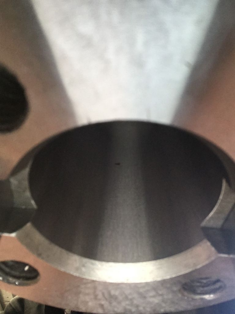
                      This photo shows the #40 spindle bore and face after grinding, run out on bore and face is now less than .0001" (.0025mm). The picture does not show up very well but the finish produced by the TPG is very good.

                      spindle bore and face. (2).jpg

                      #492917
                      Mark Rand
                      Participant
                        @markrand96270

                        Nice!

                        #493938
                        Lex Davis
                        Participant
                          @lexdavis38817

                          Does anyone with a Mk2 know where the return spring for the quill is located, the parts manual does not show it.

                          I need to get a bit more tension on mine somehow but I don't want to start pulling things apart until I know how the spring is set up.

                          #494030
                          Mark Rand
                          Participant
                            @markrand96270

                            Haven't got a Mk2, but most mills have the return spring in a housing right beside the quill downfeed handle.

                            Usual method, if you need more tension is to wind the quill down till the pinion is off the end of the rack, supporting its weight as you do so (after removing the depth stops/covers etc. that will prevent the quill from going that far), then give the handle a bit more rotation to wind the spring up some more. Then push the quill back up so its rack engages the pinion, reassemble and bob's your uncle.

                            The fun starts when the clock spring decides that it isn't going to play and either breaks at the end of becomes unhooked from the inner and outer retaining screws. Then you have to take the cover off and hook it back together…

                            #494117
                            Lex Davis
                            Participant
                              @lexdavis38817

                              It's not a simple matter of rotating the pinion a bit because that will move the position of the dowel pin that acts as the Zero position stop. There must be some way to apply more tension directly to the spring but I think that the spring is either in the Quill casting or the feed gearbox housing on the left, it is not on the handle side of the head.

                              Edited By Lex Davis on 04/09/2020 04:37:46

                              #494129
                              DC31k
                              Participant
                                @dc31k
                                Posted by Lex Davis on 04/09/2020 04:36:26:

                                I think that the spring is either in the Quill casting or the feed gearbox housing on the left, it is not on the handle side of the head.

                                It is on the handle side of the head.

                                Look here:

                                https://www.model-engineer.co.uk/forums/postings.asp?th=91397&p=2

                                post by Paul Major 09/02/14 23:03:40, sixth photo of post.

                                The spring is inside the left hand gear.

                                #494173
                                Lex Davis
                                Participant
                                  @lexdavis38817

                                  Thanks for the information DC, I completely missed the spring in the parts manual but it definitely is in the down feed handle gear as you and Mark suggested.

                                  #494641
                                  Lex Davis
                                  Participant
                                    @lexdavis38817

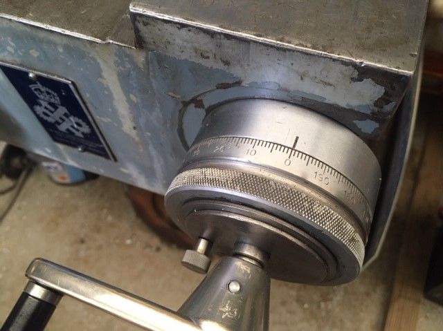
                                    Before I start making a new dial, as one of mine is missing,though I would ask the question here first – what are my chances of finding one of these anywhere around the world? I need the 0- .200" dial for the x axis.

                                    beaver dial.jpg

                                    #495070
                                    Lex Davis
                                    Participant
                                      @lexdavis38817

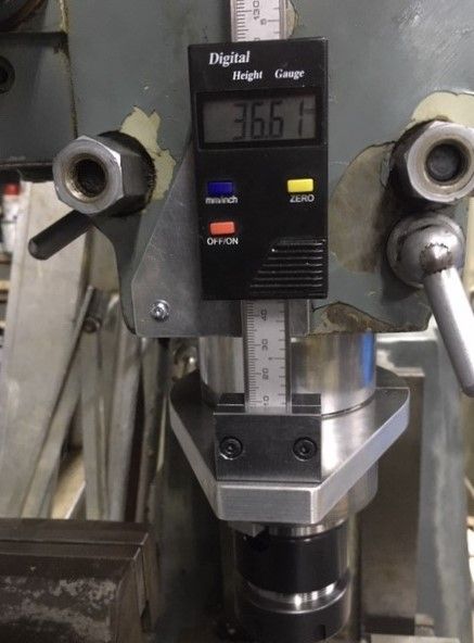
                                      A handy addition to the Beaver that I have been working on for the last few days. I think it looks a bit "agricultural" but it is very useful and easily removed if required.

                                      img_2409 (2).jpg

                                      #495920
                                      Ian Bowers
                                      Participant
                                        @ianbowers85137

                                        Hi

                                        another question my MK1 has grease nipples on the slides, is this correct as I thought oil would be a better lubricant?

                                        Ian

                                        #495962
                                        Mark Rand
                                        Participant
                                          @markrand96270

                                          They are oil nipples, not grease nipples.


                                          If grease has been used on the ways, remove the table and the knee and clean the oilways out with oil!

                                          Edited By Mark Rand on 15/09/2020 17:48:24

                                          #506992
                                          Petr Jicha
                                          Participant
                                            @petrjicha68595

                                            Hi

                                            I have a vbrp mk2 beavermill and i could not find anywhere what oils go into the head?

                                            Could someone help with what oil goes in there?

                                            Thank you.

                                            #507571
                                            Lex Davis
                                            Participant
                                              @lexdavis38817

                                              The oils specified in the 1970"s operation manual are no longer available, although alternative oils of equivalent specification are. I just use ISO68 hydraulic oil as most of it leaks out anyway. Any oil of roughly the correct viscosity is probably better than running it dry.

                                              #522666
                                              Harold Jolly
                                              Participant
                                                @haroldjolly73409

                                                hello I'm new to the group would to now if any one has copy of the manual for the balding beaver Mk5

                                                #534764
                                                Brian Skidmore 1
                                                Participant
                                                  @brianskidmore1

                                                  Hi all! I’m refurbishing a beaver mk1 bvrp . I’m after some photos of leadscrew at nut end . The issue I have is at some time some one has fitted a piece of .500” stud into end of leadscrew presumably due to damage. I’m hopping to find out how the radial thrust bearings on leadscrew mounting on end of table are adjusted at ball crank in behind bracket. Ideally a photo of end of leadscrew on left underside of table showing arrangement at back of ball crank/leadscrew bracket would be ideal. I’m assuming there must have been a portion of larger diameter thread with couple of lock nuts on . Any help/ advice would be greatly appreciated. Many thanks, Brian skidmore.

                                                  #535128
                                                  Mark Guy
                                                  Participant
                                                    @markguy26995

                                                    Hi mine has two nuts on the left side but they are not underneath. My lead screw has also been repaired at some point ( badly) but it does work ok. I also re ended the right side with a piece of .500 bar which I bored and tapped 7/16 unc and locktighted in, which did make a job of it. I will put some pictures of the left hand ball handle showing the adjustment. I have the power feed gearbox built up and ready to go back on so I will get some pics of that too and put them on this page

                                                    #535145
                                                    Brian Skidmore 1
                                                    Participant
                                                      @brianskidmore1

                                                      Hi Mark, Thankyou for reply and pictures, obviously seems a bit of a week point on these mk1’s, pretty much same story with this one. I was lucky with feed box on this one apart from a sheared bolt on top of box with enough sticking up to get hold of to remove. I notice that on left end of lead screw there appears to be the internal part of a ball bearing, which may have been used as a spacer to pack out screw, or I wonder if may have been a bearing. The reason why I’m curious is that on mine the two lead screw carrier brackets are not the same, one has a recess on back, I assumed was to accommodate drive sleeve/gear when table fully wound over. But seeing the left hand end of your lead screw I wondered if it may have been a bearing pocket and that carrier bracket may have been on left side of table. In the past when end broke off lead screw I wondered weather things may have been swapped around for whatever reason just to get machine working again. So I’m interested to now if yours has recess on one of carrier brackets and if so which end of table it was fitted? On mine the left hand ball crank had been bored through and some material taken off of face next to dial so that a slim nut was fitted to adjust end float with two small radial thrust bearings either side of bracket. I’m sorting this machine out for a good friend off mine and have rebuilt head successfully, and this forum has been such a great help as no manual/parts books available for this model. If this was my machine I would probably consider a ball screw conversion and beef up end of leadscrew and thrust adjustment. I guess that’s why there where mk2’s and so forth. I own Bridgeport Witch I rebuilt some years ago and had collum,knee,saddle and table reground and scrapped by Braithwaite’s up in Yorkshire, which was worth every penny. 20 years ago. I must admit I like some aspects of this Beaver as so much more robust and rigid than the Bridgeport particularly the int 40 taper. Thanks for you prompt reply again Mark,
                                                      Best regards, Brian Skidmore

                                                    Viewing 25 posts - 101 through 125 (of 192 total)
                                                    • Please log in to reply to this topic. Registering is free and easy using the links on the menu at the top of this page.

                                                    Advert

                                                    Latest Replies

                                                    Home Forums Manual machine tools Topics

                                                    Viewing 25 topics - 1 through 25 (of 25 total)
                                                    Viewing 25 topics - 1 through 25 (of 25 total)

                                                    View full reply list.

                                                    Advert

                                                    Newsletter Sign-up