Thanks Peter, I never knew there was a keyway there. Moved the head straight again and managed to free the quill back up. Only seems to happen when hard machining at an angle. I'll take that plug out and see what condition of the key way is in
It just occured to me – how on earth do their quill removal instructions work without removing that key? I can't see how the quill can be pulled out without removing the key, but I have done it myself!
I am rebuilding a MK1 Beaver that unfortunately had the head bearings (not the quill) removed. I bought the mill in bits and although it is all there and I can reassemble it all, the bearings themselves are missing and were lost by the original owner during the process of finding replacements.
The problem is that the bearings specified in the MK2 manual are not the same. Does anyone have a MK1 and happens to know all the bearing numbers, if so that would be fantastic as I am pretty stuck at the moment.
Also is anyone aware of a parts manual/list for the MK1?
The original fitment was a pair of Hoffman 135ACD angular contact bearings at the bottom and a Hoffman 130 type 100 deep groove ball bearing at the top.
for the bottom ones. I can't remember what the top one is equivalent to, but it's a simple 6000 series deep groove ball bearing, so the spindle and quill diameters should let you choose the right one.
Tony at lathes.co.uk has got such manuals and parts lists as are available,
I finally got around to removing the Quill/Spindle assembly from my Mk2 #40 taper machine. It really is a simple , straight forward procedure if you follow the instructions.
I was surprised to find that the 2 locknuts (items 52 & 53) on the top of the spindle were completely loose and had allowed the spindle to drop down a couple of millimeters.
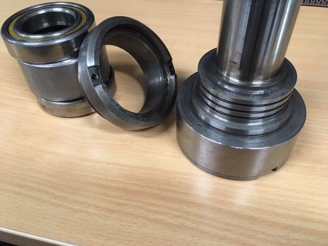
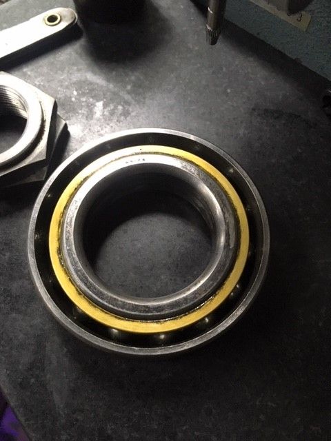
After removing the Spindle Bearing Nut (item 62) I carefully tapped the spindle, complete with bearings and spacers etc, out of the Quill to have a look at the bearings. The lower bearings are Hoffman N9126 with dimensions of 40 x 72 x 17mm. These are no longer available so I will have to clean them out and re lubricate then see how they perform.
It doesn't do any harm to use some low strength 200 series Loctite on the two locknuts. Torsional vibration from a worn drive spline (especially with a shell/face mill) can rattle them loose.
I guess that Beaver were pretty limited for choice in making space for the 40 taper spindle in the existing quill. Opening the bore out to take the more common 80mm OD bearings would be very marginal.
You are correct Mark,the N9126 bearings were a special size made specifically for the Beaver milling machine.
It's a pity that the Beaver manuals did not keep up with the changes made to the various models over the years, the manual that I have does not show these bearings at all and other parts are completely different to what is shown in the manual.
I have a VBRP Mk 2 which is missing the taper dowels for head location and I wonder if anyone could give me the taper dimensions so that I can make 2. The drawing in the manual shows it to be a much steeper taper than normal for a taper pin. ? Anybody got a spare one? or a drawing which gives dimensions?
I have wondered about fitting tapered alignment pins to my Mk1 along the lines of the Mk11, but aren't sure as yet how repeatable the other parts of the nod/swivel arrangements are even if they seem to be a good fit still.
Hi my Name is Brian Skidmore, I have a question about a VBRP mk1 Beaver turret mill I’m rebuilding head on for a friend. Have already found this forum very useful source of info regarding spindle bearings ect. My question is about belt box , there are two angular contact bearings that the front pulley runs on , I have made a new dog clutch shaft that engages back gear . And on this machine there is no spacer to control preload on angular contact bearings. I have made a new nut with locking system to control and set preload but am now wondering weather or not there may have been a spacer between these bearings, the machine has undoubtedly been apart in past and I wonder weather it may have been left out. I’m hoping one of mbrs of this forum may have had experience of this part of machine , as you are probably aware there are now parts diagrams of mk 1 .
looking forward to hearing any reply’s . Many thanks , Brian.
Hi, I'm new to this forum, I have a Mk1 Beaver VBRP, I had the head motor converted from star to delta a few years ago running from a single phase to three phase using an inverter. With the price of inverters having significantly reduced now due to the Chinese manufactured units, I have just fitted one to my table feed, but find the gearbox quite noisy! So will need to look at stripping and rebuild, I have a mk2 manual but unfortunately have not been able to find a copy of mk1 anywhere, just wondered if anyone might be able to help. I am happy to share any information I have from the Mk2 manual if anyone's requires it.
I have finally had a chance to remove the bearings from my spindle and I am not impressed with what I found. Someone has obviously been in there before and really made a mess of it. The outer bearing spacer has been surface ground to about .005" less than the inner spacer and both spacer are out of parallel by at least .001".
There were also burrs and dings everywhere, not to mention that the two top locknuts were loose.
There are no actual seals on this spindle just a type Labyrinth setup at each end.
just seen four findings on striping the spindle on your beaver mk1 , . I can imagine very frustrating. But hopefully recoverable . I fitted new spindle bearings to the one I’m rebuilding for a friend and was lucky just a bit of fretting on bearing spacers where the top lock nut had also been loose at some point , I cleaned them up on my 540 J&S , I don’t yet have a rotary grinding fixture so had to do them linear ,gave them a very light clean up Together , I fitted new bearings of type mentioned on this forum and so far have been very pleased with result . Regarding belt box bearings and lack of thrust control spacer, I ended up making one as I came to the conclusion that there must have been one originally and also made a much more beefier lock nut fitted with Soft pads under grubs screw to prevent loosening and Damage to thread on pulley shaft. Found issue with bull gear not coming into full mesh with pinion witch judging by wear patern on teeth had probably been run for some time in this condition and making back gear quite noisey. This issue was solved by use of shims on pulley shaft to change alignment and also increasing depth of dimple that detent ball locates in on sliding bull gear.(I found considerable wear on dimple allowing gear to float and not positively hold in position by detent ball) after this was sorted bull gear now locates in full mesh and now runs considerably quieter especially at higher rpm or back gear.If your machine is noisy , I would advised checking the bull gear is in full mesh.i could imagine this could be an issue on these BVRP mk1’s. hope you manage to work around issues you have found Dave.
ps any luck finding any literature or parts diagrams on these mk1’s?
Hi Brian, the Bull Gear etc will be the next area that I delve into, I wonder what I will find in there. My machine is a Mk2 so I don"t have any info on the Mk1.
I have now realized that the bearings were set up in the DF configuration but from the information in various bearing books I have decided to set them up as DB and after grinding the spacers in small stages I am now at a point where the 2 spacers are nearly identical in height and preload is nearly correct which brings me to believe that this is the way they were intended to be fitted.
I now have a small amount of preload on the bearings with the inner spacer now measuring .0031" (80 microns) less than the outer spacer. I don't think that these bearings were a matched set of Duplex bearings with the correct amount of offset ground into the faces.
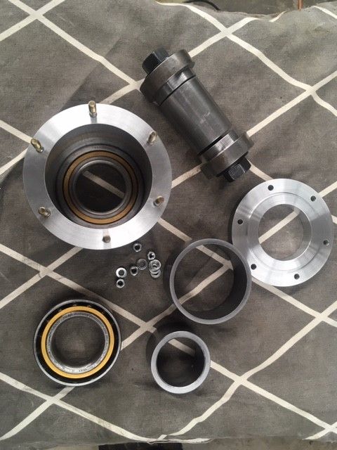
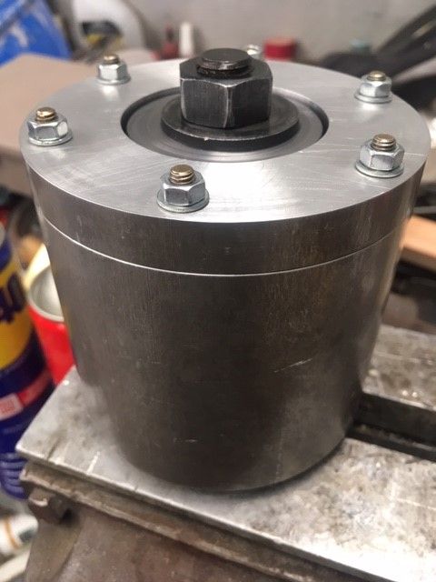
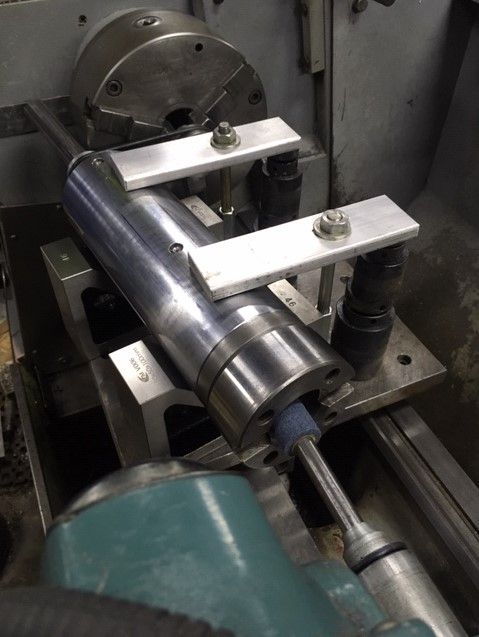
This is the Bearing Preload Fixture that I made to simulate fitting the bearings and spacers into the Quill/Spindle assembly. It allowed me to quickly determine the difference in spacer height required. I found that a small change in spacer height (3 microns) makes a big difference to the torque needed to rotate the bearing assembly.
Put my Mk1 VBRP head back together yesterday with its replacement five-speed poly-V pulleys. Top speed is now 4000 rpm.
I've almost finished making a new drive bush (the bit that has the internal spline to drive the spindle). Just got to turn a groove on it to locate the back gear. The original appears to have been a soft steel and the splines are worn to the point that there is 9° of play. This made interrupted cuts noisy and destructive.
A new back gear pinion is also being fettled, since the replacement I put in a few years ago has been wrecked by the hammering.
The replacements are EN24T, but I'll be sending them off for nitriding as well.