Don't know about removal, other than removing the nut from the top of the drawbar and taking it out downwards. The reason is almost certainly that the splined part Beaver spindle isn't really big enough for a 5/8" drawbar. So it's probably 1/2" (same as the NMTB30 spindles) with a larger extension at the lower end where there's more meat on the spindle,
Edited By Mark Rand on 11/03/2019 21:54:04
Yeah i did consider the downward route Mark, top nut is welded on though, so it would be grinder time…….will have to be done. Been considering adapting to a power drawbar anyway, so now might be the the time.
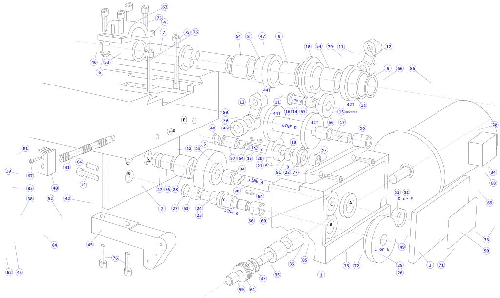
Here is an uncompleted QCAD drawing/tracing of the expoloded view of the VBRP II table (X) gearbox. On later MkII's a modified version of this gearbox was used on the (Y) carriage. It's an exported boitmap but anybody with registered QCAD is welcome to the DXF for their own use. The table drive version is shown being stripped down in the VBRP MkII restoration thread.
Yes, I know the perspective of the caphead screws is wrong, nothing looks right however I do them!
Thanks to Robert for starting this thread and to all who contributed. I am a new member on this forum with a VBRP – 2 in Australia and have been searching the internet for detailed information on these machines, without much luck.
The information that I need most at the moment are details of the Y axis Gib Strip, a sketch with dimensions would be great, if anyone has ever had to make one.
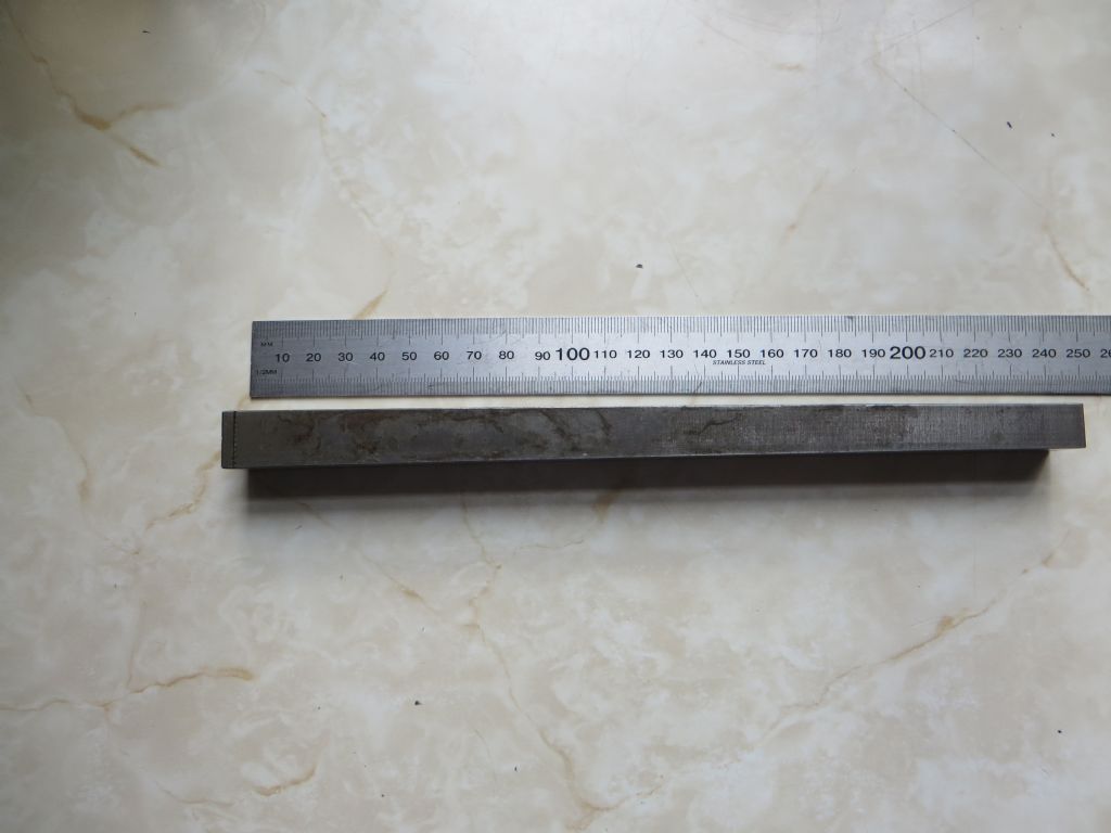
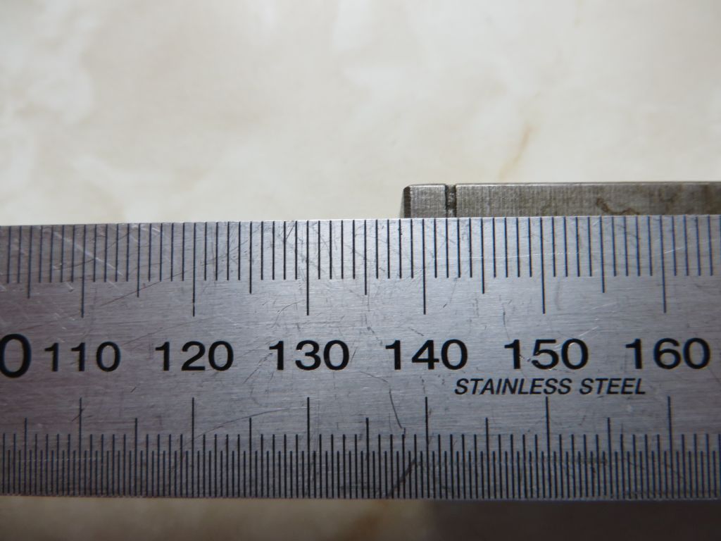
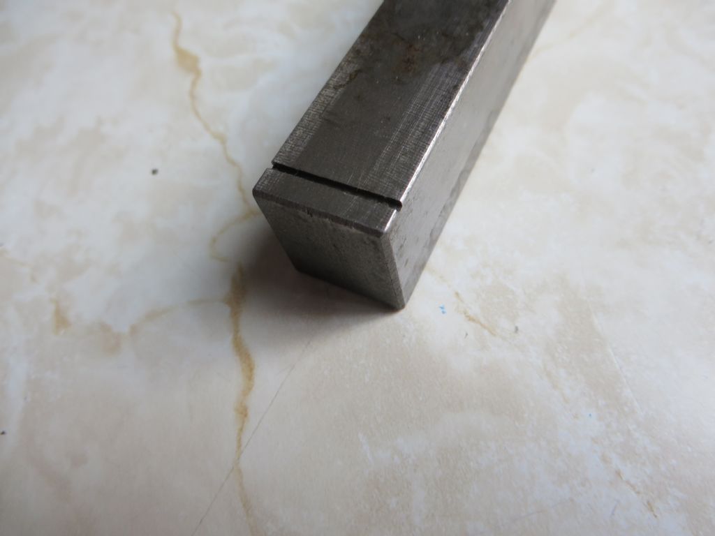
The gib has a single simple taper. It is rectangular with parallel sides 0.745ins (18.923mm) apart. The tapered sides are 0.496ins (12.598mm) at the narrow end and 0.658ins (16.713mm) at the wide end. The two parallel side are machined and the two tapered faces are ground and scraped. Hardened steel again IMO. There is a small groove about 30 thou wide and 30 thou deep across the top parallel face at the wide end, about 0.15ins in from the end. The gib is 241mm long overal
…
And later replied to Martin :
Given that the original part was probably Imperial, and allowing for wear, my guess of original dimensions are :
I honestly don't know Lex. Could possibly be a channel for lubricant. The exploded diagram shows almost nothing of that area, and it doesn't really show up in any of the photos posted by rebuilders.
Thinking about it, it probably engages with the gib adjusting screw at the front. I believe that screw has a flange on it and that flange could engage in the gib key slot.
You're right. I had a look yesterday and was reminded that there is (obviously) another screw the other end of the apron, so the gib is adjusted between the two screws. The slot remains a mystery. It is small, less than a millimeter I would say, unlike the X axis gibs which both have a much wider and deeper slot for adjustment.
Thanks for the pictures Peter, do you think that is the original or a re-manufacture gib strip? Would you mind snapping a shot of it from each side when you put it back together?
Definitely original. It is my spare so my machine isn't disassembled. Can you explain a bit more what you want photos of please?. Meanwhile, is there anything in the other thread that helps?.
Just a guess, but I'd say it's a replacement with a small, caught, measuring oops.
There are times when I wish my Mk1 was a Mk2, because of the things they put right in the newer designs. But it'll still out live me and is more accurate than I am.
There is nothing in the other thread that shows the details that I am after Peter. What I would like to see are pictures of each side of the Gib and Adjustment Screws because the table is 10" wide and the gib strip you showed is 10" long therefore the adjustment screw heads must end up proud of the side of the table on at least one side.
One adjustment screw is missing from my machine so before I make a new one I would like to see how it was set up originally.
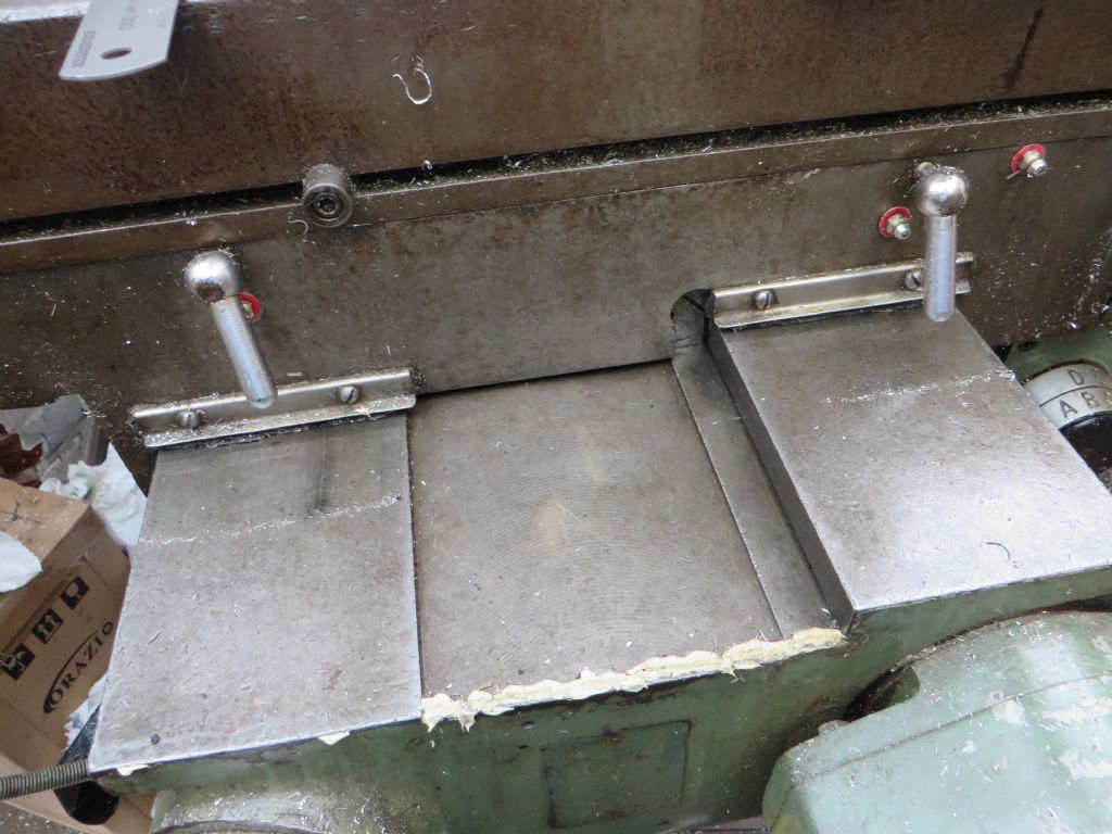
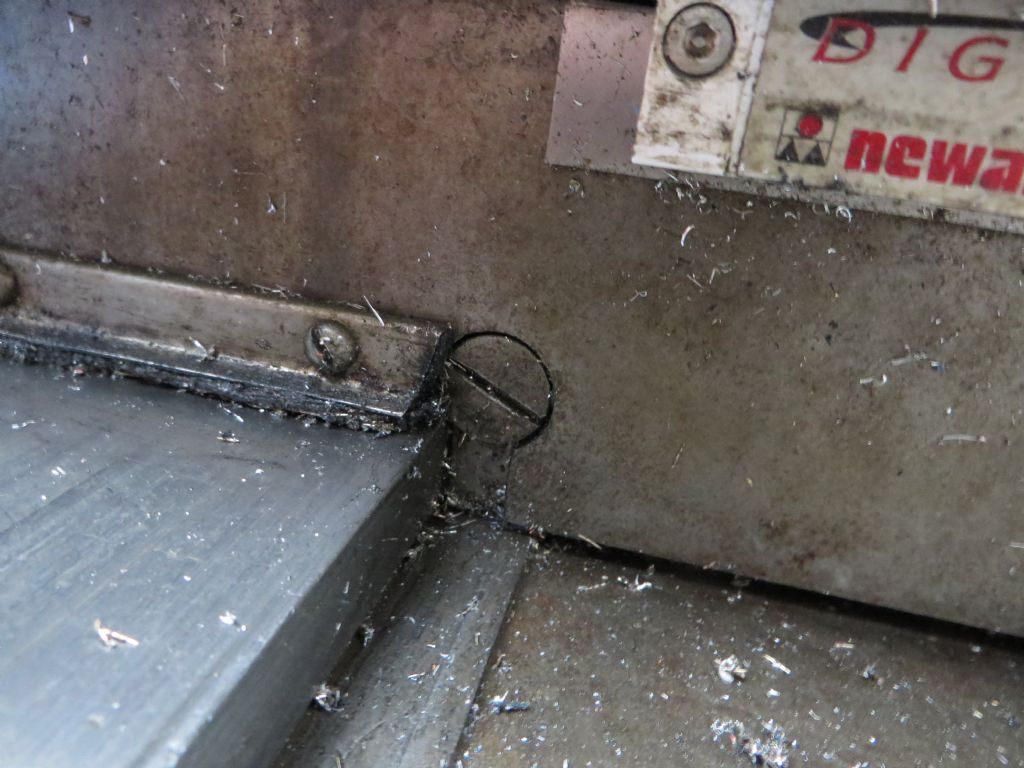
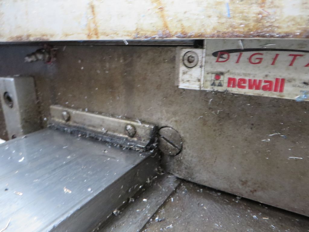
Near the blue letter A in a circle, at the bottom of the picture, you can see a gib adjusting screw touchung the gib.Look at the opposite end of where the gib sits and you can see there is a pocket for the other adjusting screw. The pocket starts and widens out at the end of the gib. Only one screw is shown, but lets hope it's the one you need.
Like most people, my mill is in assembled and in use, and the apron assembly is the other way up, so I'm definitely unable to take pictures of that area. I could take a picture of the front and back gib screws in situ if that would help?
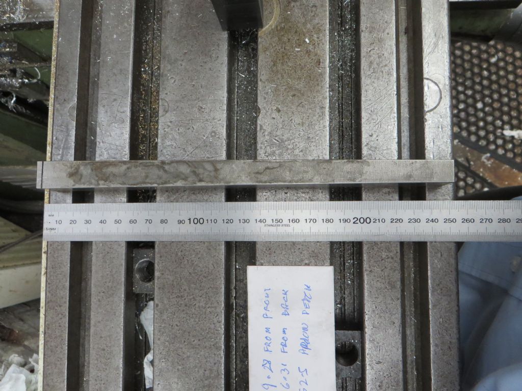
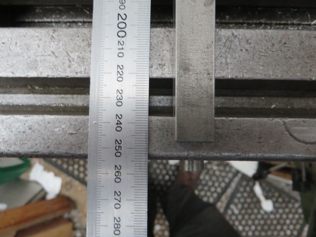
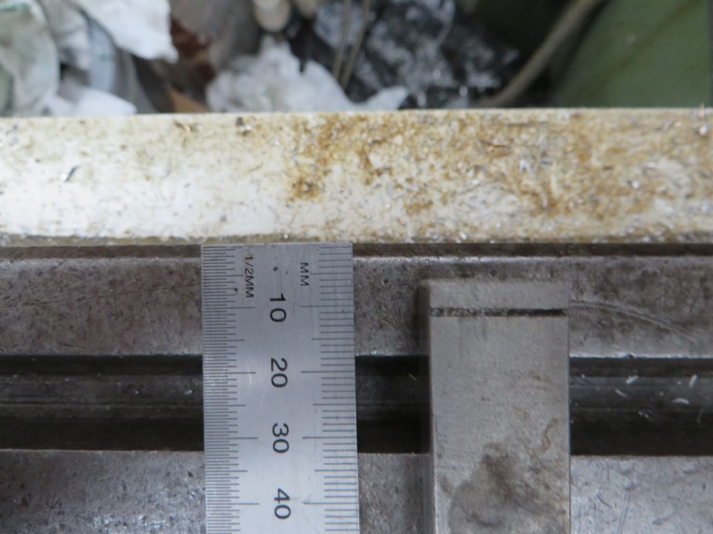
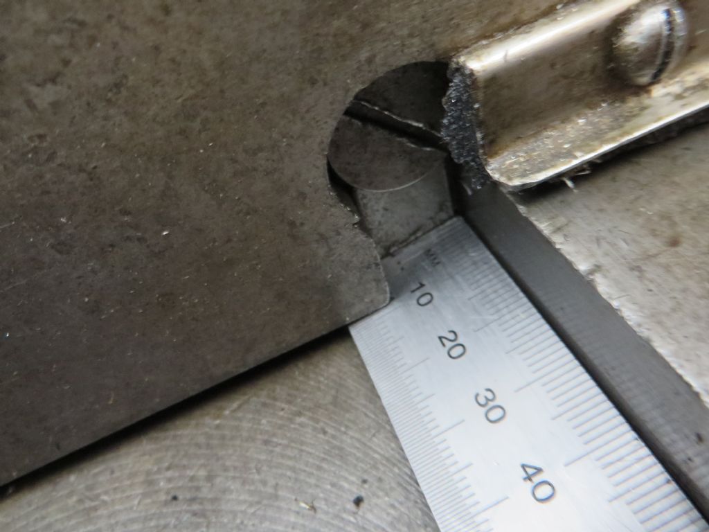
Later… I've just done some measurements and photos of the mill. Yes, the table is about 10" wide (I see 255.0mm). Underneath, at the height the gib is at :
Apron measures 252.5mm wide.
Front of the gib 9.28mm from the front of the apron.
Rear of the gib 6.31mm from the rear of the apron.
Calculate the gib length from that gives : 252.5 – 9.28 – 6.31 = 236.91mm
The spare I previously measured at 241.3mm, so there a couple of mm descrepancy, which I can well believe from these rough measurements.
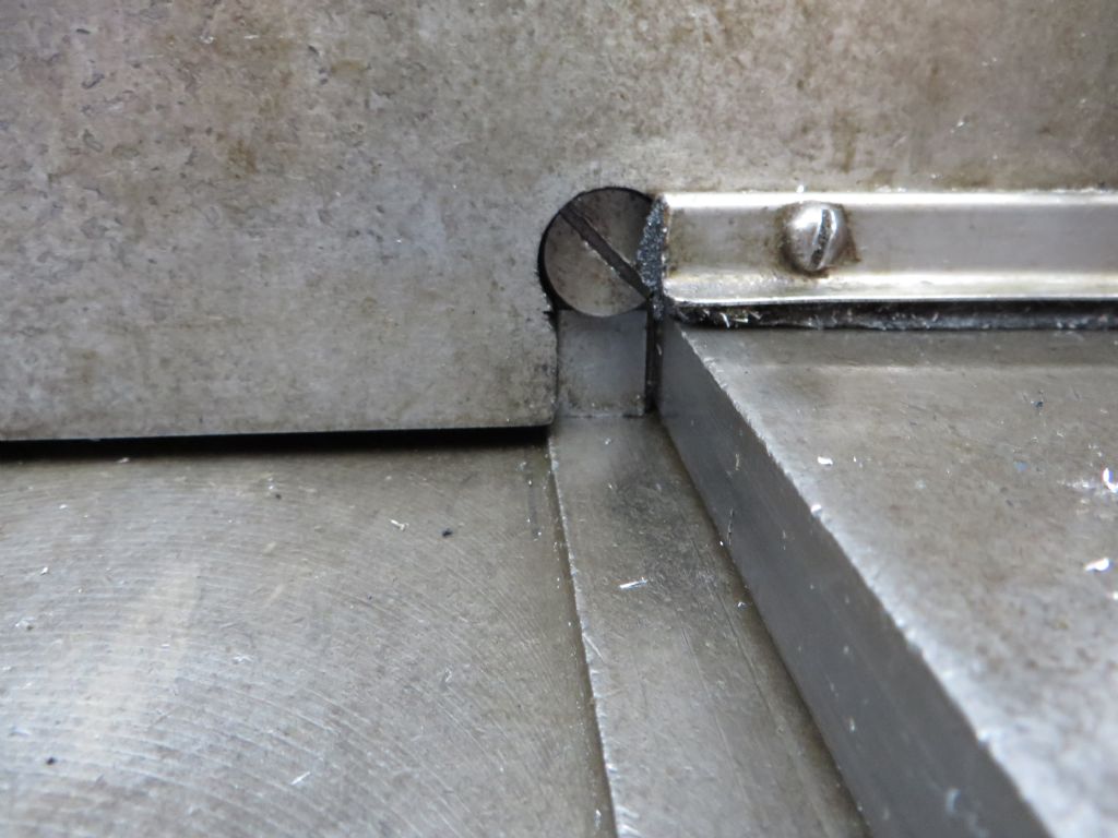
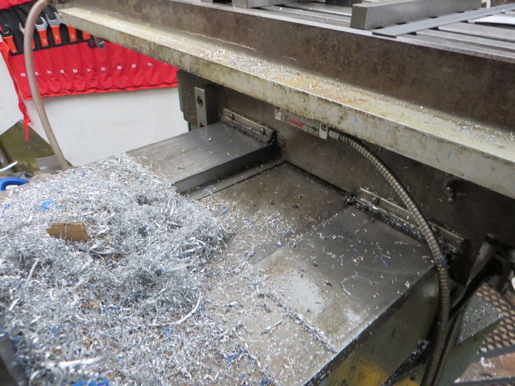
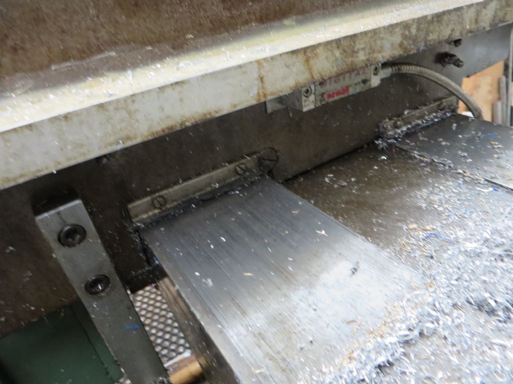
Like you, I had the image in my mind of the screws being wholly in front of and behind the gibs. In fact, the screw (assy?) is mostly above or to one side of the actual gib key.
These pictures may help. Sorry for the space, I can't see how to do thumbnais.
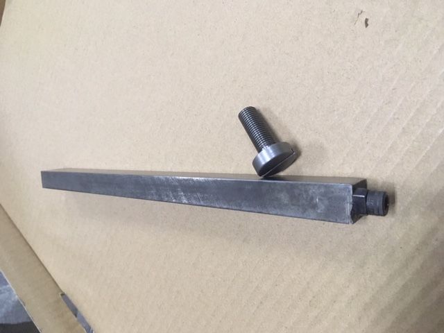
Thanks for taking the time to post the pictures Peter,they have confirmed that the gib arrangement is exactly the way that I thought it would be. I can also go ahead and make some way wipers as per your photos, as mine are all missing. I made a new adjustment screw (see photo) to replace the missing one and will also have to make a new gib strip, the one that was in the machine may not be original and has had some makeshift extension fitted to the large end, it is also too short at 223mm.
Good news Lex. Just shout if there's any more photos you want, like a close of of the wiper. I can easily take one of those off . Looks like the wiper material is felt.
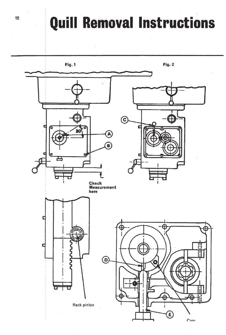
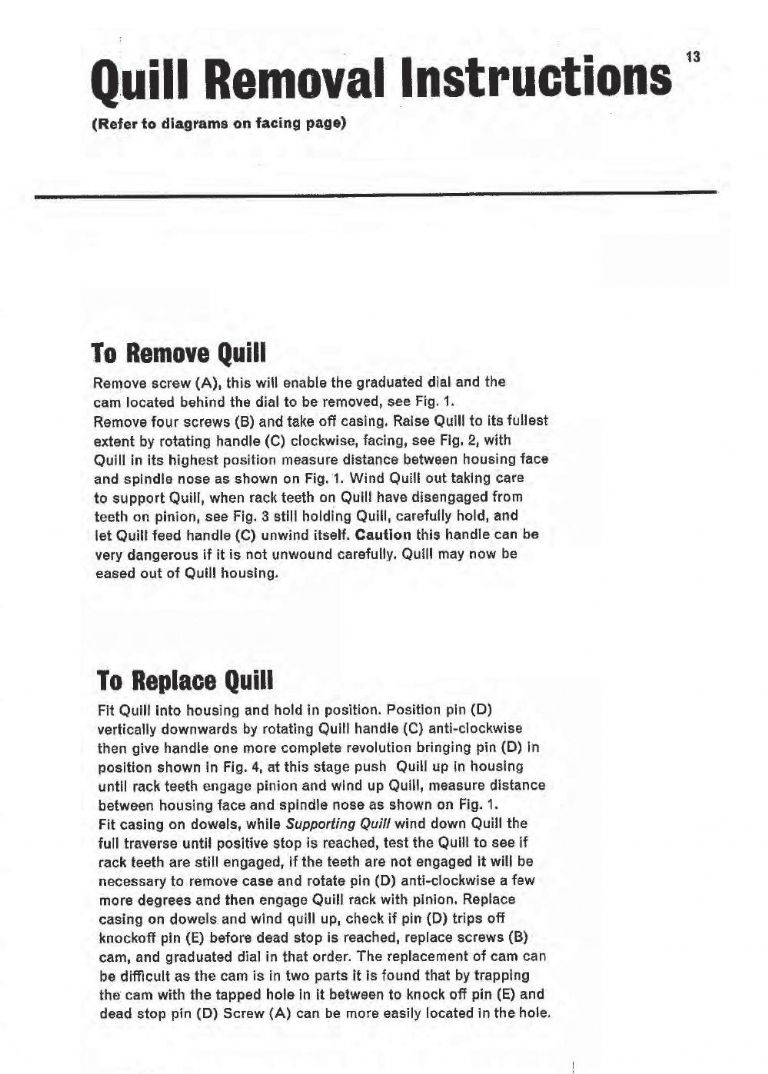
Thanks Peter. The MKll spindle has been mention in this and another thread and also the fact that the information in the Beaver manual is not very clear, as I have found out myself, so I would like to know about the procedure to correctly remove the spindle including how much of the head needs to be disassembled to do so. Looking forward to hearing from others who have done this,
You have to remove the quill by following the section in the manual "P12-13 Quill Removal Instructions". Don't forget to remove the drawbar first. The procedure is much much easier if you turn the head to one side first. Don't be tempted to try remove the spindle from the quill while the quill is still in the machine. The torsion spring which balances the weight of the quill assembly is quite dangerous until you follow the procedure to unwind it. It housed in the box on the right of the head, around the shaft of the quill operating handle. That's the handle that smacks you in the face if you don't release the tension properly .
There have been several variations in bearing types. Earlier machines had a pair of opposing taper roller bearings at the bottom and an angular contact bearing at the bottom. The later machines have a matched pair of opposing precision angular contact bearings at the bottom and an ordinary sealed deep groove bearing at the top. The spindle should come out of the quill fairly easily. Remove the spindle nut at the top of the quill, then the whole spindle assembly will get jacked out as you remove the quill bearing nut. The bottom quill bearing nut is actually the full diameter of the quill and around 17mm high. From memory, I think it needs a big C spanner to remove – it has two shallow opposing slots for getting some torque on it. Be careful of the felt seal at the bottom of the quill, which runs on the inner bore of that lower 'nut'. Mine had hardened and broke up and I was stupid enough to not take any measurements of it. If you get a chance, please measure it for me!. Also make a note of the directions of the pair of angular contacts. I can't remember for sure if the open sides face each other or face away from each other.
The angular contact bearings are separated by a pair of cylindrical spacers, one on the inners and one on the outers. The difference in length of these spacers, a few tens of microns, sets the preload on the angular contact pair, so be careful not to ding them, deburr them, clean with emery, etc.
If you replace the bearings don't be mean, they need to be precision matched 7207's.
No, the quill plus spidle shaft is free to pull right out. The spindle is only connected to the drive train by splines. So the spindle+quill assembly will come straight out of the bottom after following the instruction on the handle/spring stuff. You then have a quill with spindle in your hands for renovation. One tip – in my case, the quill was such a good fit in it's bore, that if I took more than a minute or two trying to refit it, the heat from my hands expanded it and it would no longer fit!
Hi I was wondering if someone here may be able to help. I've got a beaver Mk2 with a wedged quill. Basically I've been machining with the head tilted at 45, worked fine then the quill jammed solid. I'm guessing the rack pinion has moved off the rack on the quill but someone hopefully has more knowledge on this. Any help is greatly appreciated
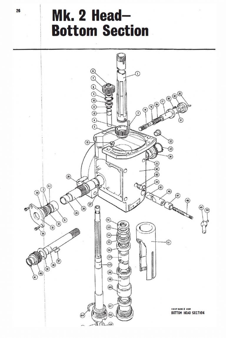
Mark – On the front of the quill housing you can see the head of what looks like a plug, about 1/2" diameter. That is the Quill Guide Plug which has a key section on the other side which rides in the key slot in the quill to stop it rotating. You'll see it in the parts listing as :
43 S100/750 Quill Guide Plug
The plug/key is itself stopped from rotating, and is retained by :
44 P185 10 UNC x 3/8" long set screw
Try to remove the plug key and see if the quill can be persuaed to move.