All things Beaver Mill

Advert

All things Beaver Mill

Home Forums Manual machine tools All things Beaver Mill

Viewing 25 posts - 26 through 50 (of 192 total)
  • Author
    Posts
  • #361375
    SillyOldDuffer
    Moderator
      @sillyoldduffer
      Posted by Michael Gilligan on 09/07/2018 18:11:44:

      Posted by SillyOldDuffer on 09/07/2018 15:03:10:

      qcad does all that for about £30. (The free version is no longer available …

      .

      Dave,

      You have me a little confused :

      I have just refreshed my "QCAD"

      QCAD 3.21.1

      These packages contain QCAD, bundled with a free trial of QCAD Professional. The trial runs 15min at a time and can then be restarted. You can order QCAD Professional from our Online Shop and download the full version immediately. Alternatively, you can choose to remove the trial and use the free QCAD Community Edition instead.


      **LINK**

      https://www.qcad.org/en/download

      .

      MichaelG.

      Sorry about that, I gave everyone a bum steer! I thought Ribbonsoft had killed the Community Edition and didn't check the small print properly. Thanks for pointing out the free version is still available

      Dave

      Edited By SillyOldDuffer on 09/07/2018 18:19:05

      Advert
      #361384
      Peter_H
      Participant
        @peter_h

        Many thanks all, I'll have a look at that software.

        > So you can't do a straight tracing and automatically get good results,

        > rather you have to translate the photo into sensible CAD dimensions

        > So you can't do a straight tracing and automatically get good results,

        > rather you have to translate the photo into >sensible CAD dimensions

        Yes, I'm aware of that problem. I've looked at photgrammetry a bit over the years, and it can be done from a single unknown camera, but only if you have some markers at known coordinates. Otherwise, you need several photos from different angles and ideally a known calibrated camera.

        In this case, the source images I'm referring to are the section diagrams in the Beaver parts manual. There are several good sectional drawings, and from my experience so far, they seem to be mostly to scale. But aside from dimensional info, which would be great, the section drawings could be vastly improved and made much easier to view and interpret. The only releiable source of dimensions we have is to measure parts as they are stripped. But there are other cluse, such as a bearing type being known from the parts list – you immediately know the bore and shaft dimensions, and they can be used as calibration points in a useful small program called "Screnn Calipers" from Iconico. They do more or less what they say, and can store several different calibrations, so you can read directly in mm or inches after calibrating against a known length object in the drawing. Obviously doesn't work well if perspective is involved.

        BTW, I saw there is an open source program called FreeCAD – is that related to LibreCad?.

        http://www.iconico.com.

        PS – I keep checking "send me email notifications when someone replies.." but I'm not receiving them.

        #361466
        Peter_H
        Participant
          @peter_h

          > take a photo and import it into Layer 0. Then create Layer 1, and trace lines over the photographic image

          Am doing exactly that now in QCAD, with a sectional view from the VBRP Mk2 manual. Pro version is 33 Euros, per year if you want updates. Ie, 33Eu gets you updates for 1 year, there after it's 33Eu per year for continuous updates.

          Excellent program, I am very impressed. It's the way Autocad should have gone 20 years ago instead of the horrible office-like toolbar. The heirachical buttons on QCAD are so easy to use. If only I could find out how to set the grid size for snap to grid!

          #361472
          SillyOldDuffer
          Moderator
            @sillyoldduffer

            Posted by Peter_H on 09/07/2018 18:53:10:

            BTW, I saw there is an open source program called FreeCAD – is that related to LibreCad?.

            It's a different project. FreeCAD is a 3D parametric CAD package, not a 2D drawing tool.

            • In 2D CAD you represent three dimensional objects with drawings of the same object from a number of viewpoints, like top (plan), side, and front. It's the draughtsman's job to make sure the three views make sense. A floor-plan might need only a top view, but more complicated objects need more, possibly also an isometric view to remove ambiguities. There are rules for doing this properly; older British drawings were done in Third-angle Projection, modern drawings are usually First-angle. Again, it's the draughtsman who does this manually. I find 2D very useful for producing templates and simple drawings not requiring professional skills.
            • 3D Parametric CAD takes a different approach. Designs are developed by defining objects, for instance a bolt might be produced by drawing a 2D hexagon, extruding the hexagon to make the head, then drawing a circle on one face of the head and extruding that to make the rod, finally applying a thread to the the rod. If 2D drawings of the object are wanted the package generates them at the end. 3D has many advantages: it's harder to draw impossible objects; objects can carry properties like the material they're made of; objects can be rotated, scaled, & stress analysed; the geometry can be exported as a cutting tool path or as layer definitions for a 3D printer, and much more. Done properly, a 3D model can contain all the information needed to manufacture it, and all the information needed to simulate it.

            I use FreeCAD in preference to Fusion360 for simple objects. However, for mechanical design, Fusion360 and other commercial products are more fully featured. May not matter for basic 3D work, but, for example, FreeCAD doesn't support joints and assemblies yet. It will let you draw all the parts of an engine, but not let you assemble them into a complete engine. Fusion360 does let you design parts, and assemble them, and by defining joints, allow parts to move on screen as they would in a working engine.

            Dave

            #361478
            Michael Gilligan
            Participant
              @michaelgilligan61133
              Posted by Peter_H on 10/07/2018 13:03:37:

              If only I could find out how to set the grid size for snap to grid!

              .

              I run QCAD on a Mac, so details may vary if you are on a different OS

              On the top menu, select |QCAD|

              From the drop-down, select |Preferences|

              In the Application Preferences pane, under 'Defaults for New Drawimgs' select |Grid|

              … Follow your nose.

              [ noting particularly, the text in Red ]

              .

              MichaelG.

              #361488
              SillyOldDuffer
              Moderator
                @sillyoldduffer
                Posted by Michael Gilligan on 10/07/2018 14:55:00:

                Posted by Peter_H on 10/07/2018 13:03:37:

                If only I could find out how to set the grid size for snap to grid!

                .

                I run QCAD on a Mac, so details may vary if you are on a different OS

                Michaels advice is correct for Linux. You can change grid for all Drawings via the Application menu as Michael describes or change it for an Individual drawing from the Drawing menu.

                Curious thing about grids – I never change them! Guess I'm lucky that the default suits what I do. The metric system is wonderful…

                Dave

                #361496
                Peter_H
                Participant
                  @peter_h

                  I could set the application preferences and change the setting for all new drawings, but I couldn't change it on the drg I had started. In fact, I could start a new drawing, observe the grid snap setting was ok, import the bitmap, and the grid snap just vapourized. Seems it was because of the scale of the drawing being so huge interacting with this setting :

                  Application Settings->Graphics View -> Grid->Minimum Grid Spacing (pixels)

                  It appears you can't snap to a grid that is too small to see, which seems a bit odd to me.

                  #361503
                  SillyOldDuffer
                  Moderator
                    @sillyoldduffer

                    Hi Peter,

                    You will soon find on this forum that it doesn't take long before the chap who first asked the question becomes the expert! You're already exploring uncharted territory.

                    However, I think you shouldn't normally need to change anything in Graphics View. I say this because I believe 'Graphics View' refers to the capability of your computer display screen, not to an image. All it means is that you can't have grid settings smaller than your computer can physically display. I may be wrong.

                    In Drawing View, which is where you work, grid settings scale automatically with the rest of the drawing as you zoom in and out. That's normally what's wanted.

                    I tried importing an image and the grid just worked as normal. I suspect your problem is due to altering Graph View settings. It's possible you're doing something advanced and have found a bug in which case the Qcad forum was helpful the only time I needed it.

                    Dave

                    #362128
                    Peter_H
                    Participant
                      @peter_h

                      No, I haven't touched any setting in graphics view, only the snap grid size under "Grid", which I changed to 0.1mm in all viewports.

                      I still have the same problem though, this time with a different BMP of similar scale.

                      Auto grid setting sounds insane. I've worked with CAD for decades and always used the grid as something to snap the cursor to when needed and I've never seen it used any other way by anuyone I've worked with. What would you use an Auto grid for?. I fail to see what use it is if it's size continually changes.

                      Anyway, the bitmaps I am importing are around 1652 x 2152. They are photocopies of sectional views from the Beaver parts manual with a scale of around 10 pixels per mm. What I am seeing after import is X and Y coord readings in QCad showing 4 decimal places of mm moving linearly with cursor movement, even though grid is set to 0.1mm, and not auto. If I zoom in close enough to see the 0.1mm grid, then the cursor is snapping to 1mm increments (NOT 0.1mm), but the coords change from (1372.1252, 795.2162) to (1373.1252, 796.2162) when moving the cursor up and right by one grid snap. Note, not only is the grid 10x too big, but there is an unwanted four decimal places hanging on the end of each coord. When I imported the BMP, I zoomed right in and put it's origin on the drawings origin.

                      #362177
                      Peter_H
                      Participant
                        @peter_h

                        Well, it seems to work with a 1mm grid now, and the image is almost 10:1, so good enough. I'm reasonably happy with my first attempt, a cross section of the backgear case and cover, traced from the sectional view of the variable speed MK2 head in the parts manual, using QCAD in the manner suggested by Dave (SOD)

                        beaver mk2 vs head hatched 4bpp.jpg

                        #362181
                        Michael Gilligan
                        Participant
                          @michaelgilligan61133

                          That looks very promising, Peter yes

                          MichaelG.

                          #362191
                          SillyOldDuffer
                          Moderator
                            @sillyoldduffer

                            Posted by Peter_H on 14/07/2018 13:17:23:

                            Auto grid setting sounds insane. I've worked with CAD for decades and always used the grid as something to snap the cursor to when needed and I've never seen it used any other way by anuyone I've worked with. What would you use an Auto grid for?. I fail to see what use it is if it's size continually changes.

                            Method in the madness. The grid scales appropriately as you zoom in and out.

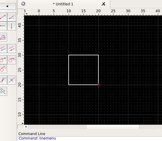
                            Here I've drawn a 10mm square. The grid has dots at 1mm.

                            qcadgrid1.jpg

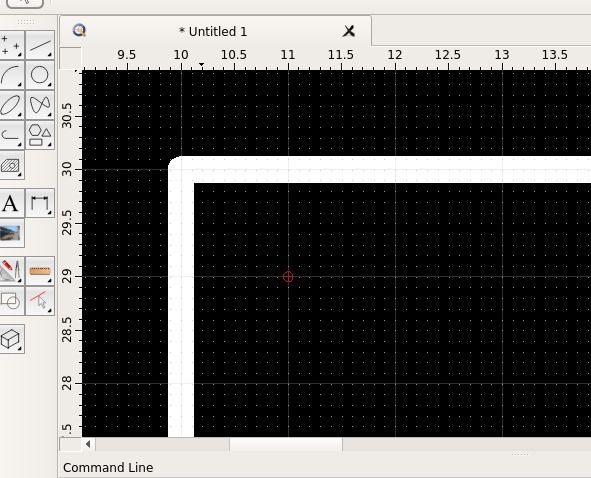
                            If I zoom in on the top left corner:

                            qcadgrid2.jpg

                            the grid scales to a more helpful resolution. The dots are now 0.1mm apart, which is helpful for working on a detail.

                            Dave

                            #362209
                            Peter_H
                            Participant
                              @peter_h

                              So what is the grid?. Is it a 1mm grid or a 10mm grid?. If I want to snap the cursor to a specific grid multiple, I want it to be defined by me. The whole idea of a grid that changes is an anathema to me. If I want to snap to a 1mm grid, I want exactly that, I don't want it to change to 10mm or 0.1mm depending on zoom level. I cannot see how there is any application for that. The only thing that comes to mind is that maybe you see the grid as some sort of visual aid, where the normal in my experience is that it is something to magnetically snap the cursor to.

                              The snap settings don't seem to be very stable either. I have twice lost application grid settings between program runs, and whether the grid icon and the auto icons, under the snap menu, are on or off at any particular time seems completely random. However many times I turn Auto off and click Grid on under that menu, they just revert at what feels like random intervals. Either there are some big bugs around this area, or, more likely, I'm missing some setting.

                              Other than that quirk, it's the best 33EU I ever spent. Excellent piece of software, I'd use it for 2D work by preference.

                              #362211
                              Bob McDougall
                              Participant
                                @bobmcdougall63250

                                Hi Peter_H, glad your Bever is coming together. Yes the top bearing on the spindle was a common ball race , only the lower two were angled. Although there are different angles you can buy, I guess the larger the angle helps if you cut more drilling than side to side milling ??? I use fusion 360 CAD which has a free version for non commertial use and can also make stl files for 3D printers.

                                #362214
                                Mark Rand
                                Participant
                                  @markrand96270

                                  I used Nachi 7207-CDUP4 bearings for the bottom pair which are a 15° angular contact, P4 or ABEC7 grade. Top bearing was a deep groove ball bearing.

                                  Edited By Mark Rand on 14/07/2018 23:58:37

                                  #362256
                                  Peter_H
                                  Participant
                                    @peter_h

                                    Bob – it seems to be more common in spindles to use pairs or triples of the 15 degree angular contacts with a degree of preload. It's a trade off between stiffness, axial and radial load capacity, and maximum speed.There is some good information in the SKF Super Precision Angular Contact Bearing manuals, including some section drawings through various examples of spindle design.

                                    Mark – I've found up the old bearings I exchanged when I partially renovated the Beaver. The lower pair were the original Hoffmann 130ACDEP's and even had the Beaver specification number N1093a engraved on them. I couldn't find any other old angular contact bearings butI did find a 6206, so it looks likely this mill had a deep groove radial bearing as well. I used a pair of Fafnir ABEC-9 2MMV207WI CR DUL

                                    Edited By Peter_H on 15/07/2018 09:44:11

                                    Edited By Peter_H on 15/07/2018 09:44:52

                                    #362298
                                    SillyOldDuffer
                                    Moderator
                                      @sillyoldduffer
                                      Posted by Peter_H on 14/07/2018 22:31:25:

                                      So what is the grid?. Is it a 1mm grid or a 10mm grid?. If I want to snap the cursor to a specific grid multiple, I want it to be defined by me. The whole idea of a grid that changes is an anathema to me. If I want to snap to a 1mm grid, I want exactly that, I don't want it to change to 10mm or 0.1mm depending on zoom level. I cannot see how there is any application for that. The only thing that comes to mind is that maybe you see the grid as some sort of visual aid, where the normal in my experience is that it is something to magnetically snap the cursor to.

                                      The snap settings don't seem to be very stable either. I have twice lost application grid settings between program runs, and whether the grid icon and the auto icons, under the snap menu, are on or off at any particular time seems completely random. However many times I turn Auto off and click Grid on under that menu, they just revert at what feels like random intervals. Either there are some big bugs around this area, or, more likely, I'm missing some setting.

                                      Other than that quirk, it's the best 33EU I ever spent. Excellent piece of software, I'd use it for 2D work by preference.


                                      That's interesting. I thought it was possible to lock the grid to work as you describe, but the application settings sort of but don't quite work as I expected. It may be worth raising on the qcad forum.

                                      Could be an example of horses for courses – you use the tool differently to me! I'd not spotted before how the grid behaves because I rarely use the grid as my main snap guide. I use it to establish the base point and it's convenient for drawing lines that happen to fit the grid. But quite often my lines don't snap to the grid.

                                      My typical mode of working often requires a construction layer, maybe several. They contain the lines, circles, intersections and dimensions that establish snap points to suit the object I'm drawing. And, the more complex the drawing, the more likely it is that lines must be referenced from drawing features rather than a fixed grid.

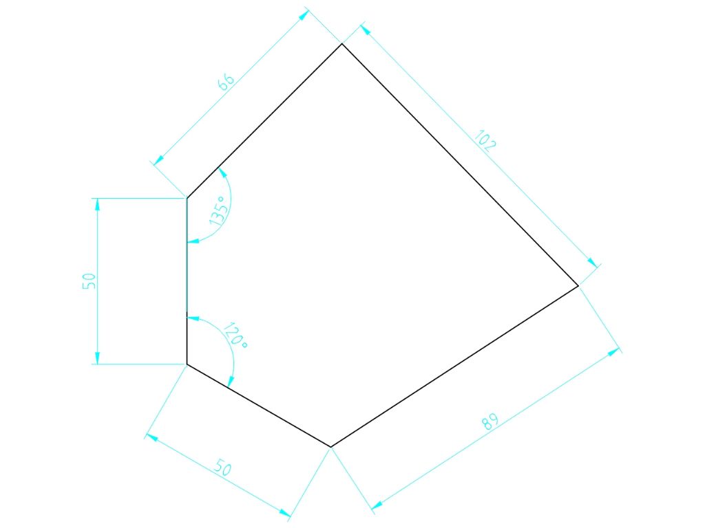
                                      Try drawing this object with the grid:

                                      qcadgrid3.jpg

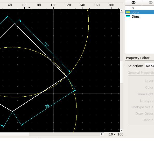
                                      While qcad's approach to scaling the grid happens to suit me, it's not good for what you're doing. It may help to keep an eye on the grid scale at bottom right:

                                      qcadgrid4.jpg

                                      10 < 100 means the dots are 10mm apart and the tiny dotted lines 100mm.

                                      Dave


                                      Edited By SillyOldDuffer on 15/07/2018 12:54:54

                                      #362308
                                      Mark Rand
                                      Participant
                                        @markrand96270
                                        Posted by Peter_H on 15/07/2018 09:42:30:

                                        Mark – I've found up the old bearings I exchanged when I partially renovated the Beaver. The lower pair were the original Hoffmann 130ACDEP's and even had the Beaver specification number N1093a engraved on them. I couldn't find any other old angular contact bearings butI did find a 6206, so it looks likely this mill had a deep groove radial bearing as well.

                                        Yep, Those are what was used on the Mk1 VBRP, at least. On the Mk 1, the angular contact bearings on the left hand side of the X feedscrew are imperial. They can be a bit hard to find…

                                        #362728
                                        Peter_H
                                        Participant
                                          @peter_h

                                          I think we'll have to agree to disagree Dave . The good thing is that it seems to cater for either way of working.

                                          I've done some more tracing of the Beaver MK2 head section, I'm actually rather enjoying it, though had tremor doesn't help much. That could be why snap to grid is important to me. I havent got the hang of the 'album' on here yet. The pictures I've posted are coming out very dull and very small, even when clicked on.

                                          beaver mk2 vs head v8.jpg

                                          Edited By Peter_H on 17/07/2018 22:50:54

                                          #372174
                                          Alf Scotting
                                          Participant
                                            @alfscotting10686

                                            Hi guys,

                                            Can anyone tell me how to remove the Y axis motor and gearbox – I have removed the 4 bolts and 2 dowels but though loose will not come away – the manual I have shows the motor going off at a horizontal plane whereas mine is vertical – I would like a more comprehensive manual but can't afford at this time the one offered on the web for 65 GBP – all switches are stuck in the ON position so I will need to remove them and spray with contactor cleaner – I think Beaver mills would be thin on the ground here in Australia so I am looking forward to corresponding with members from there place of origin

                                            #372265
                                            Mark Rand
                                            Participant
                                              @markrand96270

                                              I'm not certain, since my one is the earlier version, but I suspect that the shaft that operates the left-right clutch fork needs to be removed. Removing the table will help to see what is happening. If you remove the handles and endplates etc. and losen the gibs, you can slide the table off, with the aid of a hoist. It's about 150-200kg…

                                              #372268
                                              Alan Waddington 2
                                              Participant
                                                @alanwaddington2
                                                Posted by Alf Scotting on 18/09/2018 00:41:12:

                                                Hi guys,

                                                Can anyone tell me how to remove the Y axis motor and gearbox – I have removed the 4 bolts and 2 dowels but though loose will not come away – the manual I have shows the motor going off at a horizontal plane whereas mine is vertical – I would like a more comprehensive manual but can't afford at this time the one offered on the web for 65 GBP – all switches are stuck in the ON position so I will need to remove them and spray with contactor cleaner – I think Beaver mills would be thin on the ground here in Australia so I am looking forward to corresponding with members from there place of origin

                                                There is a PDF manual floating about, think it was Russ B that sent me a copy. It’s on my hard drive somewhere, Will have a look for it and come back to you .

                                                #372391
                                                Alan Waddington 2
                                                Participant
                                                  @alanwaddington2

                                                  Alf, have sent you a PM regarding manuals.

                                                  #379726
                                                  Phillip Hancock
                                                  Participant
                                                    @philliphancock13014

                                                    Sorry to be asking for something on a first post but this Beaver manual that’s about does it cover a Mk1 as we have a Mk2 manual but the machine is a mk1 and we have a problem with the quill power traverse in that it seems like something has sheared or stripped internally between the handwheel and the spindle as engaging the drive from the spindle does not stop the handwheel turning by hand with the spindle stationary. A copy of the mk1 manual would be rather helpful if possible.

                                                    #399782
                                                    Alan Waddington 2
                                                    Participant
                                                      @alanwaddington2

                                                      Have had my Beaver for a good while, but up to now never had cause to remove the drawbar. Until today that is……….Tried to fit an INT 40 boring head, only to find it has a 5/8 imperial thread rather than the M16 of the majority of my tooling.

                                                      No problem, just remove the the M16 drawbar and make a new imperial one, easy peasy…….except unlike every other mill i’ve owned, the drawbar won’t come out, it withdraws around 150mm and then hits a hard stop.

                                                      Manual offers no clues, on the drawings the drawbar is just a long bolt through the quill, which is what i expected ?

                                                      Any ideas ?

                                                      Edited By Alan Waddington 2 on 11/03/2019 21:45:11

                                                    Viewing 25 posts - 26 through 50 (of 192 total)
                                                    • Please log in to reply to this topic. Registering is free and easy using the links on the menu at the top of this page.

                                                    Advert

                                                    Latest Replies

                                                    Home Forums Manual machine tools Topics

                                                    Viewing 25 topics - 1 through 25 (of 25 total)
                                                    Viewing 25 topics - 1 through 25 (of 25 total)

                                                    View full reply list.

                                                    Advert

                                                    Newsletter Sign-up