After a long holiday in the Slough of Despond (not of Berkshire) I've tentatively picked up Alibre Atom again.
On several occasions I accidentally picked "New Part" instead of "New Design" in Assembling something. Disastrous! That loses the Assembly drawing!
The little back-stepping arrow on the tool-bar is inactive in that situation; so is there any way to recover the assembly-drawing immediately prior to the mistake? Or is it lost, at least back to the last Saving?
.
Also, can a part be constrained only once? I'd concocted a simple shaft with several parts along it*, but having placed imported components concentrically on the shaft, I could not see how to put them in face-to-face contact. You cannot select a surface facing away from you. Anyway, even trying it only raised "Over-constrained" warnings.
(Nor come to that, how to place a Part at a set distance along another.)
.
[*Part of a back-gear type speed reduction for driving a horizontal milling-machine. I was not so daft as to try to represent the gear-teeth, but drew the two wheels by their pitch cylinders.]
You should only get over constrained issues if you generate conflicting constraints
Constraints can get fiddly at times but are an acquired skill worth pursuing
Movement can also be rendered jerky by your cpu struggling with too many things going on
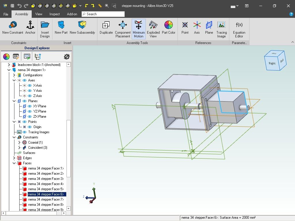
I always face my surfaces before selecting them but there may be a not-facing solution in the left hand menu if you know the name of the surface you are looking to select
edit: yes the drawn widget menu can be opened up and expanded then the face highlighted for non-facing selection
Click on the arrow to the left of the named widget to open it up
" is there any way to recover the assembly-drawing immediately prior to the mistake? Or is it lost, at least back to the last Saving? "
When I started in CAD (many moons ago) I got into the habit of saving what I was doing every 10-15 minutes. Only takes a couple of seconds to click on the save icon. Then you have only lost minutes work and not hours.
If you have made a mistake in a part, do not save it as you exit and do not save any assemblies that contain the part, otherwise all parts in the assembly will be saved and updated with the mistake.
"You cannot select a surface facing away from you"
You can easily select the surface of a part that is facing away from you I do it all the time. Just hold down the two mouse buttons and manipulate the part so you can see the side you want.
New part/design
If you click the wrong insert part rather than insert design it is just a case of then clicking the "save" icon top left and when the box comes up to save the new part click the "cancel" box and that will then take you back to the assembly you were working on.
Ah, but I don't know what makes constraints conflict, and what I was trying to do does not look as if they would. One to align one part with another, then a second to slide it lengthwise.
I have found that the index in the left-hand column highlights a failed constraint in red, and you can delete it safely. (It's not done anything.)
.
I thought if you try to rotate the figure half-way through a particular operation like constraint, that diversion closes the original operation. I could not pick up a face by identity, only the edge or the outer (visible) surface.
.
I don't think my PC struggles with running Alibre, certainly not with my modest drawings, though I follow the suggestion in the exercises to turn the "Ambient Occlusion" tool off to save processing and memory. (Is it a shadow effect with a fancy name, as its own symbol suggests?)
Drawing gears just as circles and cylinders is an old manual-draughting convention, but I don't think it would hurt at least at my level in CAD; and in any method the pitch radii are what dictate the shaft centres. I know it would be necessary at a more advanced level needing a more realistic image, or of course designing the gears themselves. I realise the trap in this simplification is not leaving enough space around the wheel for the tooth addendum.
I have though discovered the radial copying tool, and used it in this particular exercise for a ring of screws or pins.
To place the parts a set distance from another click the two surfaces say end of the shaft an done face of the gear, it will automatically assume you want the two to line up and highlight "coincident" which is the icon with the two blue boxes touching. You need to select the icon next to it where the boxes are spaced apart called "offset" you will then get a box come up to enter a distance, + or _ depending which way you want it offset.
This shows how to get out of a wrongly selected new part, moving the assembly about (hope you are not using that funny mouse again) so you can see the faces you want to select and lastly use of coincident and offset
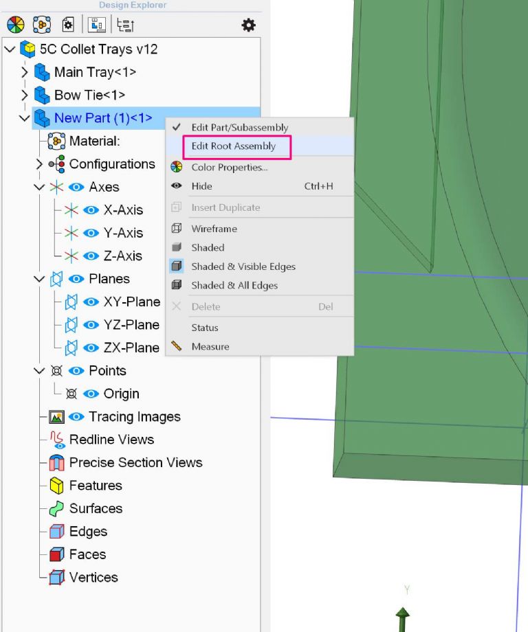
Another way to recover from an accidental New Part, is to right click on the New Part in the Design Explorer, then click 'Edit root assembly' – this returns you to the assembly level.
You can now click on New Part (in Design Explorer or the 3D workspace) and press Delete on keyboard.
I take it you mean by "movement app", animation. Yes, I know this can be a very useful tool but I'll leave that to the experts for now. Not much use animating something unless you can draw it in the first place!
.
Jason –
Just watched your video. Not very easy on my monitor as enlarging it to make the labels readable started to make them go all fuzzy!. Still, I think I got the gist of it.
I'd been trying to use "Component Placement" but it would not place anything, and I don't know what it's really for and what conditions it needs to work. Similarly with the Constraints – they seem very particular about the objects and how you use it, so the combination made me think that if you assemble two parts into contact they become one.
I often had the constraints tool "stick" on one thing, the one I didn't want, even after closing it and trying again, and still have these "over-constrained" errors for no obvious reason.
I also had one part facing the wrong way but could not rotate it no matter what I did. I thought there is a thing called "Flip" and I looked it up in the manual, but that didn't help me. This proved it does exist but bound up with something else. I think I was looking for the wrong tool for the purpose.
.
Funny mouse? It's not even mouse-shaped!
Yes – I went back to it after the conventional mouse I bought proved even worse. Its two switches were controlled by springy bits of the plastic cover, so had no positive, reliable action; not very cheap but nasty. I tried an older but much better-quality mouse from my spare computers, but it didn't work on this PC.
The thing I have replaces two buttons with a rocker-switch, and the scroll-wheel with pressing the rocker centrally so it works both switches while you move the device as a whole. It works but does take a bit of practice and is not really ideal for a mouse-enthusiastic CAD programme, but at least it is not knackering my shoulder like a mouse-shaped mouse does.
If you need to swivel a part in assembly put your mouse over it, press and hold left-shift, then left-click-hold on it, and it will swivel on gimballs through 360 in any direction you move your mouse to
Thats your problem if your "mouse" has a rocker switch you can't hold both down at the same time which is the easiest way to move the assembly or part about so you can see any side of it. You do have the View Cube, if you have that toggled on then you can drag that about with a mouse left button or just click any of the six sides.
As for flipping the part around I told and showed you how to do that in your previous Alibre thread, the red & green arrows what will "flip" the part around.
If you go back to the start of that video you can also see me moving the view about, each time the mouse changes from an arrow to the near full circle with an arrow on each end I am holding down both buttons and moving the cheap non positive clicking mouse about.
I'd not seen that control before. I was trying to assemble two parts, one with a spigot to fit a socket in the other, and that was the part facing the wrong way.
Jason –
I know, and use, that view-cube and the little view symbols on the tool-bar; but as far as I can make out they affect the whole drawing. This drawing had two objects. I wanted to turn one object round while keeping the other still.
.
A conventional rocker switch won't work as we want, no, but this instrument is different. Depressing the centre of the rocker itself presses both switches together, or operates a third, central switch. Either way, it replaces the scroll-wheel action with moving the whole thing, though it is not so easy to operate.
The previous version I have is called a Penguin by its makers, and humorously suggests an Antarctic bird in formal dinner-dress. It has a scroll-wheel and a rocker-switch as buttons, respectively the bird's beak and bow-tie. In computing terms it is a wheel "mouse" turned on its side. Unfortunately it won't work on this computer.
Both instruments are a little like a joystick, and designed to minimise limb problems by being held and operated in a much more natural way than by the ordinary digital rodent.
The design of that mouse I had bought is so poor that its switches are just not positive and reliable. Instead of two keys in slots in the case, patches of the case itself are made to act as quasi-buttons. You need push just the right spot quite hard for it to act at all. It has a tiny scroller, but awkwardly placed. So this device puts heavy, un-natural stress on your fingers and hand; not right for frequent button-pushing and holding; not only in CAD but also e.g. photo-editors and spread-sheets.
I know, and use, that view-cube and the little view symbols on the tool-bar; but as far as I can make out they affect the whole drawing. This drawing had two objects. I wanted to turn one object round while keeping the other still.
Your original post was about not being able to see a face to click on it. That is why I have told you how to move the image about so you can see what you want to click on.
Your post last night was about having concentrically constrained something which is what the "flip" option sorts out if it is the wrong way round and that is where I set the video posted today to start. Watch the video and you can see me flipping the part one way and then the other about half a dozen times using the red/green arrows on the "flip" tab
I found the two arrows again, but though they obligingly turned the thing round after I'd highlighted the two faces I want in contact, that's as far as it goes. I can't make the rest of the assembling work.
There's clearly a lot more to this "Assembly" and "Constraints" business than meets the eye, and I am probably missing something obvious to everyone else but not to me….
You said it is a spigot and something that fits on it. You said you have done the concentric constraint (hole on spigot)
You now say you can have the part with the hole in it the right way round.
All that is left is position along the spigot which I described yesterday and is done by using "offset" if you don't want your chosen two faces inline with each other.
Post a photo or screen shot of where you are at and tell us what you want to do. Or post images of the two parts and tell us how you want them to go together even a fag packet sketch will do.
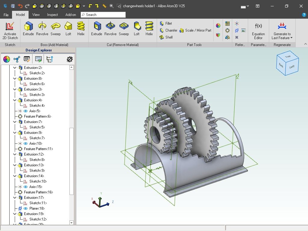
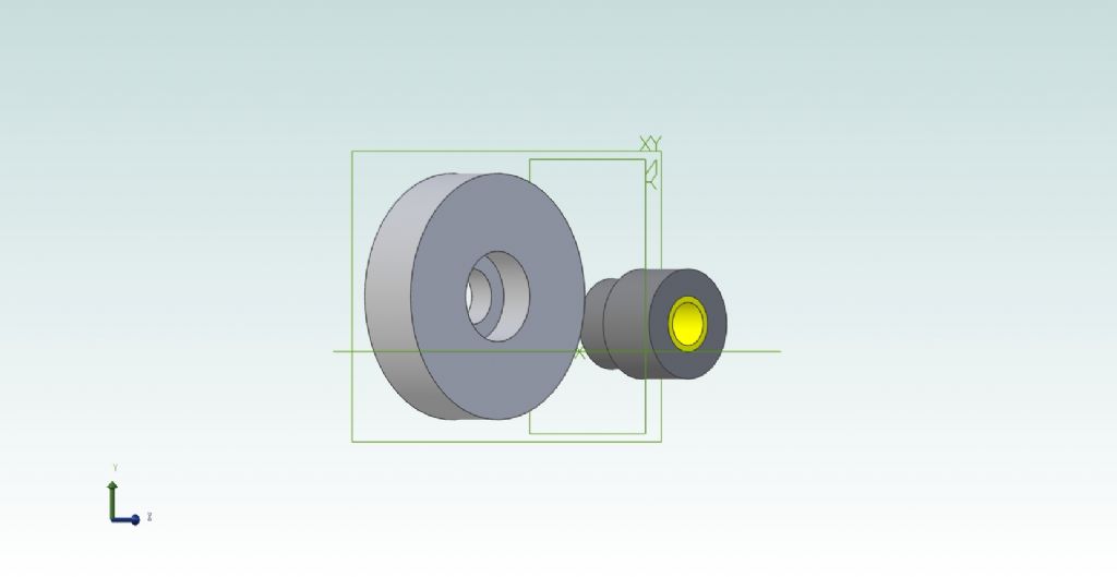
This is it. They are meant to represent two stock gears, by their pitch cylinders.
The spigot on the smaller one is as manufactured, intended to fit in a recess bored in the larger wheel, though not to full depth to give a small clearance between them..
That was the one the wrong way round, but I managed eventually to twiddle it round – once you told me how!
What more do I want to do? Finding the IQ allegedly I once had would be a start!
Author
Posts
Viewing 19 posts - 1 through 19 (of 19 total)
Please log in to reply to this topic. Registering is free and easy using the links on the menu at the top of this page.