Thankyou Jason!
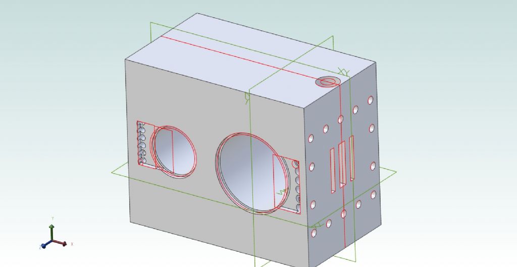
Yes – I drew the block from measuring it on a table alongside the computer.
It's not quite right. I think some of the dimensions on the drawing are a bit out.
The block is not fully symmetrical. The centre-lines of the bores are at different distances from the port-faces, though the ports are symmetrical to the depth of the block. Also the two stud-holes at each end of the port face are spaced slightly towards the sides to allow some room for the valve-spindle and its bush and gland.
'
Sorry – I'm not sure how you make something symmetrical as you say. I had turned the Grid and Grid Snap off as advised, and that makes the starting rectangle aligned with the grid but not the big dot in the middle. So had to place everything by dimensions from the edges.
'
I found how to use the array tool to make the rows of passages and the longer rows of stud holes. Ideally the drilled passages should slope down through the block for more sealing area, more room for fastenings, and minimum clearance volume…. but I'd made it the safest way I could at the time, and drew it as I'd made it.
'
I drew it after a lot of trial-and-error as a half-depth block in which to cut the two recesses that on assembly would form parts of the steam-passages. Then mirrored that, before cutting the two bores.
However, I found it very hard to calculate the sizes of the cutting rectangles for the HP side, leading first to biting into the block on both sides of the cylinder, then landing short so I had to take a second extruded cut at it. I think this is why the drillings on that side bite into the port wall. I could not make the holes tangential to the right edge, due to having two slightly overlapping sketches.
I tried to remove the faulty sketch lines but couldn't, so how do I do that?
..
It was also difficult to make the passages meet the ports, mainly by mis-measuring but I was not sure if the cutting depth was from the block surface or recess floor of the recess. In hindsight I ought perhaps have done this:
– Form the half-block, on the XY plane.
– Cut the outer port and all the passage drillings into them at each end.
– Cut the passage recess.
– Now mirror-copy the block to itself (to the XY plane.
– Cut the bores and on the crank-end face, their registers. (I have made the bottom closing plate, a rectangle in 3/8" thick steel, using a rotary-table to create the two shallow upstands that engage these registers.)
– To each end in turn, add the exhaust-port and its stud pattern.
– Add the crank-end cylinder registers.
'
It would seem to use CAD efficiently without mistakes hard to put right, needs planning the drawing order, often but not necessarily always the physical making order.
The reason for now drawing the cylinders formally is to try to deign modifications that will overcome the built-in problems I did not or could not foresee. Short of buying a new lump of iron completely……
'
One of my hopes by using CAD is that I can make copies on which to experiment. There are no full-size drawings to help me. The cylinders are also very prominent, In full-size they were between and slightly behind the driver's and mate's shoulders.and I am trying to represent fairly from a few old publicity photographs, something impossible to model to rivet-counting standards.
What I think are the starting-valve and its handle, are also prominent, on the back of the HP valve-chest. It must have been very awkward to operate there, while having also to use a globe-valve regulator – oh, and steer the wagon.
This valve and its associated passages are also something to accommodate. Helped by the overall slab-like appearance of the whole assembly. I think I can cut deep lightening recesses in the block, in which to install the passages as pipe fabrications, concealed under cladding. The starting-valve itself, if I have identified it as that correctly, is exposed.
.
Besides, the photos all show the originals differing in details. Hindleys built a large number of engineering products in a wide range to good designs and quality, some now preserved; but their steam-wagons were perhaps not among these. Compared to their contemporaries from the major makers, they were rather crude even for their time. The largest fleet was probably that owned by Pickfords, but for reasons I don't know, the haulier and furniture-remover went over to using Foden wagons; a big blow to the North Dorset manufacturer.
One Hindley steam-wagon was bought by C.W. Harris, an engineering firm in Chewton Mendip, near Bristol. Harris made petrol motor-cars under the "Mendip" brand; but also introduced a steam-wagon badged "Mendip" and looking very suspiciously Hindley….
Nigel Graham 2.


