Thank you Lee.
At 70, "deadline" is rather appropriate given that I embarked on this project in about 1978, with a gigantic mistake in trying to build it half-scale, started again at a more sensible one-third scale in the late 1990s, and two house moves and spells of utter loss of motive since then, still have a huge amount of work to do on it!
It is not easy to design, CAD or not, and I cannot guarantee it will even work.
I have always been a slow learner, have never been able to learn anything to a very high level, and 3D CAD is no exception.
'
A log of how I produce a drawing, as you suggest, would be a very long list of stupid mistakes, trial and error, objects in the wrong places, multiple attempts and deletions, very many "Undo" and "Esc" presses. It could only be a document as I cannot make a video like Jason's.
.
I've looked at Jason's video just above and tried again more or less as he does it; as a completely new Part.
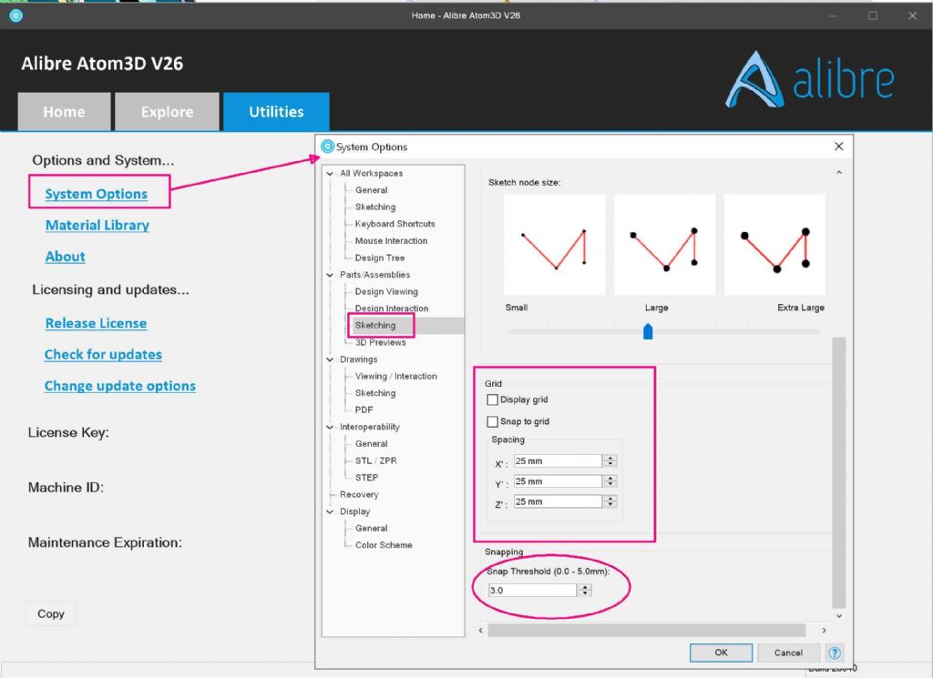
It took ages to make the hole circle because I could not see how to place the first circle where it should be. It kept sticking to the origin and I don't know why, nor how to stop that happening.
Eventually, with help from the Alibre Manual, I learnt how to use the Points and Move tool just enough to put a copy in the right place. Then I needed work out what the repeat tool means by "Centre", and how to select it.
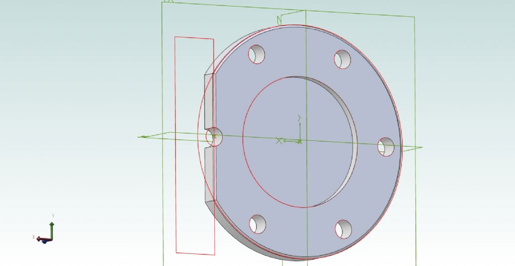
So I could now make the basic shape: a full disc with a circle of holes. (Plus the register on the inside face and recess on the outside – those were easy).
.
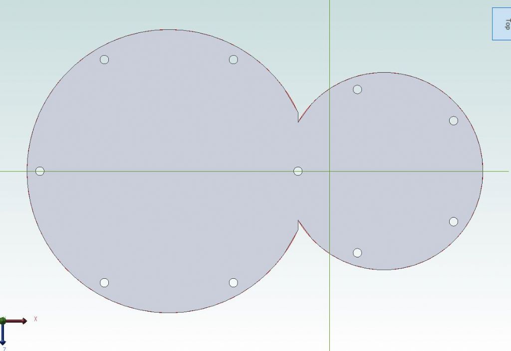
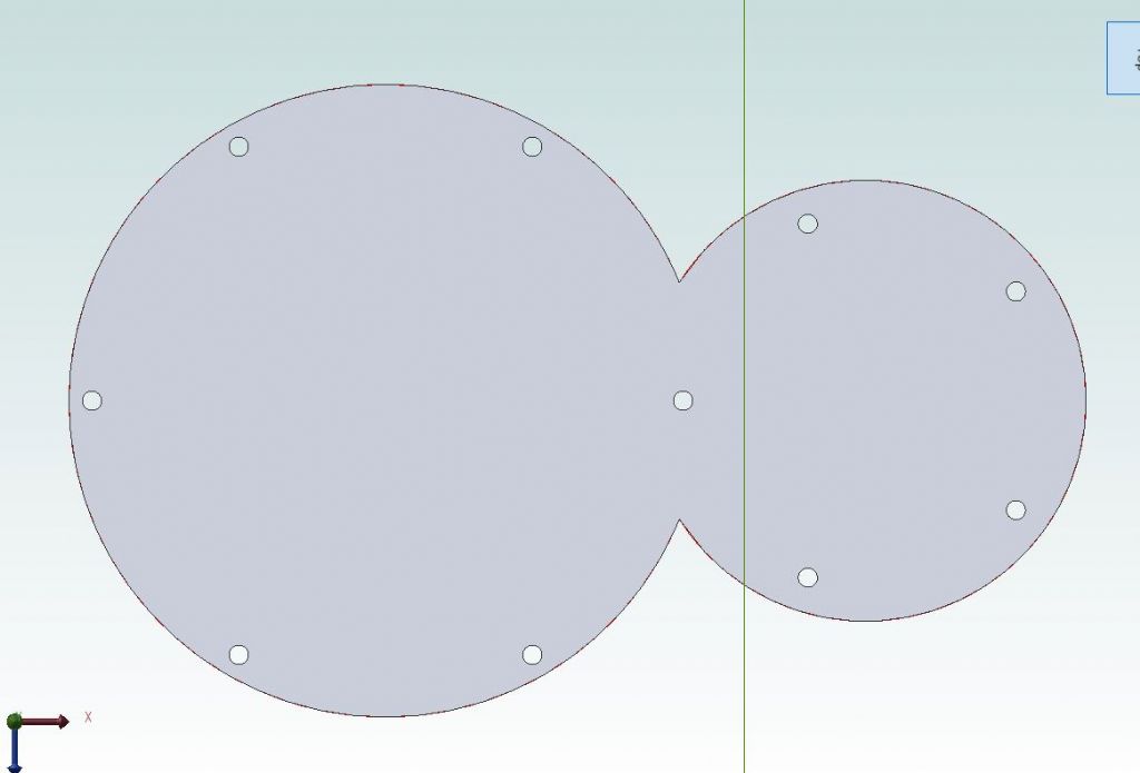
Next to cut the segment from the side……
Jason shows doing it by developing a rectangle with its long edge the right distance from the centre and extruding that through. So that's what I tried….
Somehow though, I cannot make the Line and Rectangle tools work. They want to start from the origin and I can't understand why. Eventually I had a rectangle with one corner on the origin, but I can't quite recall how. I don't think it was simply clicking in two places. I tried various possible ways to move it to where it should be, but they all failed so the wrong methods – but I've no idea what.
'
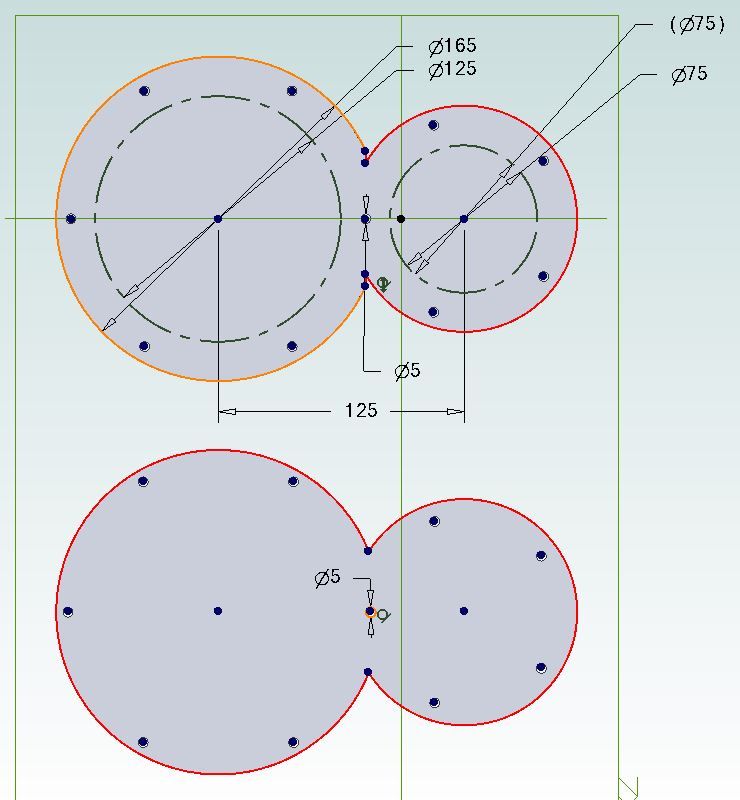
Worryingly, for much of the time in Sketch Mode the outlines of the figure were red or orange (hard to tell which) suggesting "Undefined". How? I set their diameters when drawing them, set the thickness for the extrusions, and either automatically or by my setting, they are concentric to the origin.
So I obviously have something fundamentally wrong somewhere, perhaps in some generic setting right from the start; but what exactly?
It was all working when I tried the set exercises, and I didn't think I've done anything different, except change the dimensions to inches as it is for a real object.
.
The number of bolt holes in it is still undetermined. I may have to make a completely new cylinder block, replacing the one I made some twenty years ago. It is bored, has the ports and passages, but I've built in a lot of serious problems. From a drawing point of view it does not matter because either 5 or 6 studs, one still shares a central stud between the cylinders.
lee webster.


