Alibre – A First Attempt

Advert

Alibre – A First Attempt

Home Forums CAD – Technical drawing & design Alibre – A First Attempt

Viewing 25 posts - 176 through 200 (of 295 total)
  • Author
    Posts
  • #644143
    Ady1
    Participant
      @ady1

      I assumed that the view cube was unavailable in sketch mode

      So you have to right-click-hold to check your aspect once things get more involved

      It's one of the programs weaknesses, you ask for a surface, click sketch, and it flips and turns into a totally different aspect

      It's not just you Nigel, its one of those things all users have to learn to deal with

      Posted by Nigel Graham 2 on 05/05/2023 23:59:49:

      Perhaps I'll leave threads and concentrate on more important aspects.


      Totally the way to go, I just bang in holes, 6mm 8mm 10mm whatever, and focus on the main job

      At assembly time I line up the holes

      Threads just consume CAD memory and do nothing useful

      Edited By Ady1 on 06/05/2023 10:27:36

      Advert
      #644144
      David Jupp
      Participant
        @davidjupp51506

        Ady – if the plane or face 'flips' when you enter 2D sketch, click the 'reset view' button on the Ribbon. That will flip the sketching plane around. Clicking it again will flip it back. If the workspace has been rolled away from 'head on' to the screen, reset view will bring it back to the head on orientation.

        All faces/planes have a 'front' and 'back' so there is a default orientation for sketch mode – but that isn't always the one that is most convenient or comfortable for a particular task.

        #644145
        Ady1
        Participant
          @ady1

          I know that bit thanks, and if you change the aspect to figure out which way round you actually are, then click reset-view it returns to the first position, which IS useful

          #644149
          Ady1
          Participant
            @ady1

            Nigel

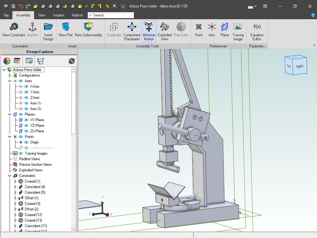
            One of my "homework" jobs was a scale drawing of my arbour press which is a relatively simple tool

            Now I use that drawing for building all my modifications and for solving any problems

            no need to go scrabbling about in the workshop trying to build stuff any more, just sip a cup of tea and ponder the task in comfort while at my computer desk, then draw the idea-parts, bring them in and check for fitments and build issues. I've already been saved from a few wasted jobs/ideas.

            When I go back into the workshop I know exactly what's needed (well 90% of it anyway)

            The time spent learning to use Alibre now really does save you huge amounts of time and effort later on

            In this example the square adapter on the nose of the ram for holding the former is too big and fouls the sheet metal being folded to 90 degrees in the die press, so that's a dead plan but Alibre meant I never had to make it to find out it was a failure

            arbour1.jpg

            Edited By Ady1 on 06/05/2023 10:59:40

            #644151
            David Jupp
            Participant
              @davidjupp51506

              Threads – in Atom3D your only options are to model them physically, or to not bother with them. You'd have to add any note to the 2D drawing manually.

              Alibre Design Pro & Expert have 'cosmetic thread' options with the Hole tool which

              • maps a thread texture image (or a plain colour) onto the relevant face of the model to show it is threaded
              • provides callout data for the thread in 2D drawings
              • uses traditional methods to show thread in 2D drawing
              • has inbuilt data for many thread types – which can be added to by the user

              The Hole tool doesn't slow the display down to the extent that modelling physical threads can, and it makes downstream drawing production much simpler.

              I agree that modelling physical threads is rarely actually needed – you are more likely to use the helical tools to model a spring, an oil groove in a bearing, or some sort of feed mechanism.

              #644341
              Nigel Graham 2
              Participant
                @nigelgraham2

                I thought I'd grasped just enough to try something of my own instead of just blindly following an exercise in the hope my results match it.

                The cylinder covers for my steam-lorry seemed simple enough. The basic shape is a disc with a shallow recess on the outer surface, shallow register on the inside; a ring of 5 or 6 stud-holes. I can work with either when I've established quite how big the steam-passages need be.

                However, it's not that simple. The cover flanges share a narrow web between the HP and LP cylinder walls. So each cover has a segment sliced off through one hole around the web's central stud.

                This proved a nightmare in CAD for what should be easy manually. It took me a long while to establish how to size the two covers so the cut line is at right-angles to the block and central to the web and shared stud. I needed, but found it fairly easy, to use TurboCAD in 2D mode only, to generate and print a dimensioned outline. Key was finding a crucial radial measurement, not feasible in Alibre, certainly not at a basic level.

                So I could now draw the things in Alibre.

                Oh Aye? 'Oo sez?

                I tried to transfer the basic drawing to Alibre as a standard CAD file, but it gave me only a 2D drawing I could save as a static Alibre ".DWG", not an active "PRT" type.

                So I started a new Part, using the paper print as my reference: as I had expected needing anyway.

                .

                The most I found I could do fully was create the outer circle.

                I planted the seed circle for the bolt-holes but it obstinately refused to be sufficiently "defined" (whatever that means) so the pattern tool cannot work. I tried everything, mainly dimensions, to find what the wretched thing wants. This also created a confusing mess because I cannot stop the dimensions all lying on each other along the axis. That's when it dimensions it at all – if it doesn't it says something about a "parametric" dimension. I've no idea what that is.

                Alibre is good at telling you you've done it wrong, but not how to do it right. It seems to need a lot of hidden conditions, and if your drawing does not meet them, nothing works.

                I tried adding lines as construction-lines, and one anyway will become the cut-line, to give the little circle a centre location. That failed: either any drawn line starts at the origin and goes off to the right or vertically instead of crossing the base circle; or I cannot make the line tool work at all.

                The Undo arrow revealed a heck of lot of failures. Sometimes I'd raise that analytical tool that shows where the faults are. That was useful to a point, unlike the manual's entry on Circular Repeats, showing how to Assemble a pretty picture of a stack of balls. (Much as I was saying by now….)

                Nor does the manual help you solve all these "Undefined" problems. It assumes you can already understand everything – so you won't need the manual and your drawings always work straight away.

                .

                In the time it took to find I could not analyse the covers' geometry in Alibre, but used an alternative approach that proved quite easy; then failed to model them in Alibre from the printed dimensions; an expert would have drawn all four, printed them off and be half-way through machining the physical parts. Before tea…

                '

                [Signed]

                Disillusioned of Dorset

                #644348
                Ady1
                Participant
                  @ady1

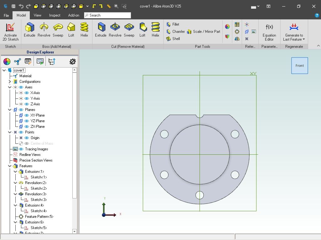
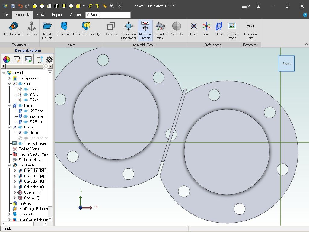
                  Did you not just make a cover with a right angled cutout then put it all together in assembly?

                  It will attach at any angle you want

                  cover1.jpg

                  cover2.jpg

                  Try drawing it in a single file and you'll go bodmin getting there

                  Edited By Ady1 on 08/05/2023 03:27:22

                  #644351
                  JasonB
                  Moderator
                    @jasonb

                    Assuming you know the ctr distance between the two cylinders and the stud PCD then that should be all that is needed. Is it a compound or double high? As teh cylinder would likely have been drawn first the cover dimensions could have been taken from that.

                    Your problem with placing the dimensions all along the axis is either not picking the right two points or simply poor mouse control, Atom will place the dims where you click so after clicking the two points move the mouse away and then click to enter the dimension.

                    #644352
                    JasonB
                    Moderator
                      @jasonb

                      Here is one way to draw it, I have done it with each feature as a separate 2D sketch so it is simpler to follow though several could have been combined eg overall circle, holes and the cut edge.

                      Recess and spigot are just circles drawn on the surface or plane and extruded or cut as needed

                      You can see that the box to enter the dimension in can be placed where ever the user wants and I drag it about quite a bit to show that. Then when entering the position of the hole I show what happens if you just click after defining the two points – the dim gets added between the two. I then delete that amd do it again but move my mouse out of teh area of the part.

                      Also notice I enter the dimension as 60/2 because I want the radius but am using a 60mm PCD

                      Finally what was learnt on the scribing block exercise can be put to use for creating the cut off edge. I use "project to sketch" selecting one of the hole sand that gives me it's ctr point. I can then constrain the rectange to that and cut the edge off. That way if I were to change the hole PCD the cutoff would move accordingly.

                      Edited By JasonB on 08/05/2023 07:34:50

                      #644354
                      JasonB
                      Moderator
                        @jasonb

                        Doing it another way round where the distance to the cut edge is known and placing the first stud hole on that edge.

                        #644357
                        David Jupp
                        Participant
                          @davidjupp51506

                          Nigel, I've said several times – if you get stuck contact me/Alibre for help. I'll either look at you files or do another screen share.

                          Rather than moan that 'x can't be done', instead maybe ask 'how can I do x?' or 'is it possible to do x?'

                          If you want to bring in geometry from a DXF/DWG, yes it opens in the Drawing workspace – from there you can copy/paste into 2D sketch of a part. The process is not complex, but you need to be aware of the steps. The basics are in the Help

                          There is a also a more detailed video (but I know you don't like videos).

                          #644361
                          David Jupp
                          Participant
                            @davidjupp51506

                            If the engine block is already modelled, it can be placed in an assembly, then a new part created in the assembly for a cylinder cover. Edges and hole locations can be transferred from block to cover.

                            Maybe a bit advanced for Nigel until more experience is built up, but all readily doable in Atom3D.

                            #644364
                            SillyOldDuffer
                            Moderator
                              @sillyoldduffer
                              Posted by Nigel Graham 2 on 08/05/2023 00:23:13:

                              I thought I'd grasped just enough to try something of my own instead of just blindly following an exercise in the hope my results match it.

                              The cylinder covers for my steam-lorry seemed simple enough. …

                              However, it's not that simple. …

                              This proved a nightmare in CAD …

                              That's right; those cylinder covers aren't "that simple"!

                              I think Nigel is trying to run before he has learned to walk. In CAD, as with almost everything else in life that's not bleeding obvious. you must grasp the basics before moving on. Confidence is good, over-confidence is bad.

                              "Blindly following an exercise" isn't good enough. Try doing the same exercise, but stop after each step and consider its purpose, asking 'what did that do?", and, "why is it necessary?" Don't jump to conclusions: if either question can't be answered, ask. David Jupp's offer is pure gold, and the forum's Alibre users know their stuff too.

                              Finally, that steam cover isn't a 'nightmare in CAD'. A trained operator can model one by applying a few few basic tools. But he has to be trained, and the hard part is learning what the basic steps are and how to apply them. Advanced CAD models are high risk if built without a reasonable grasp of the basics, and the software behaving oddly is a symptom of earlier operator mistakes. I crashed Solid Edge last week!

                              Dave

                              #644377
                              Nick Wheeler
                              Participant
                                @nickwheeler

                                Posted by SillyOldDuffer on 08/05/2023 09:48:54:

                                Finally, that steam cover isn't a 'nightmare in CAD'. A trained operator can model one by applying a few few basic tools. But he has to be trained, and the hard part is learning what the basic steps are and how to apply them. Advanced CAD models are high risk if built without a reasonable grasp of the basics, and the software behaving oddly is a symptom of earlier operator mistakes. I crashed Solid Edge last week!

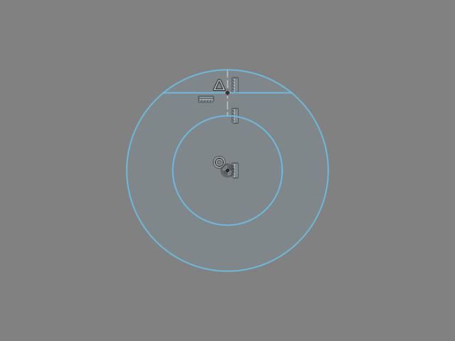
                                That cover is two concentric circles, a construction line, a 'solid' line and a point all completely constrained:

                                headsketch.jpg

                                That's hardly complicated, is it? The geometry is fixed, so the actual dimensions are largely irrelevant. Although I would have modelled the cover in place at the top of the cylinder, using projected edges and known dimensions which is even easier.

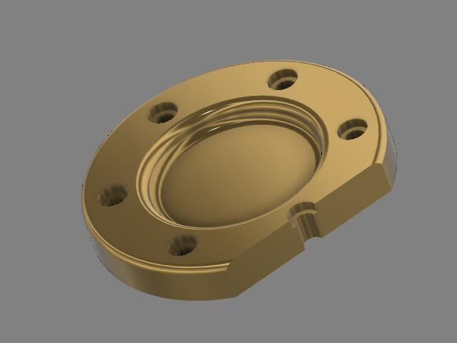
                                Then it's an extrude for the cover and another for the recess. Use the hole tool centred on the point and a countersunk/counterbored/stepped is easy. Pattern that as required around the part's axis. Use the 'solid' line to cut off the corner. Finish with fillets/chamfers as required. In brass:

                                brasshead.jpg

                                #644387
                                Nigel Graham 2
                                Participant
                                  @nigelgraham2

                                  I've no proper drawings for any of this project; just a few ancient publicity photographs and one or two leading dimensions like the wheelbase and cylinder size. I made from these, some scrappy manual and TurboCAD drawings for various parts. Most of what's on the real thing is determined by measuring the pictures and parts I've already made without knowing what problems they will give, sometimes literally years, in the future.

                                  I've reached a point I really need get things down on paper – manually or by CAD – before wasting yet more metal, electricity and hours on endless re-working.

                                  '

                                  Jason's model is what I was trying to achieve.

                                  The cylinder covers looked simple, similar to an inconsequential Alibre exercise I had already created, a disc with a circle of holes. They proved so difficult, they showed I cannot draw the other parts or their assemblies.

                                  I planned to draw the outer circle, then the holes, Trim the outline back to a line, then trim that line to form the edge; Extrude the combination, then make the register and recess.

                                  Easier than the tutorials, using elements from them. Why should that fail?

                                  The first screw hole was "undefined", Alibre told me, so useless. I could not draw the straight line where it should be; usually, no line at all. I have no idea why!

                                  .

                                  Why:

                                  A tiny, crossed-through circle next to the cursor? The Manual shows only a plain circle when the Circle tool is selected.

                                  Objects permanently "defined" by size or location but not both (coloured orange), so useless?

                                  The dimensions all lying on the axis, an illegible mess?

                                  Some dimensions impossible to make? The flag said "parametric", but what was? What does it mean? The Manual does not explain it.

                                  The few lines I managed to draw were all locked to the origin and axis?

                                  More often, I could not draw any line at all? I can draw with any certainty, only concentric cylinders around the origin.

                                  '

                                  The Manual assumes you can't go wrong and it will always work. It does not explain where and why you can go wrong, and how to avoid doing so.

                                  The trial licence has only a week to run and despite a promising start, buying the licence is becoming now an expensive gamble.

                                  Thank you for the offer, David, but I can't keep troubling Mintronics every time I try to use Alibre by asking such totally basic questions.

                                  '

                                  No, I haven't tried to model the cylinder block, all circles and rectangles all at right-angles or parallel to each other. I have drawn it orthogonally in TurboCAD but though it's obviously easy for the experienced to draw it in 3D in Alibre, I doubt I could.

                                  #644394
                                  David Jupp
                                  Participant
                                    @davidjupp51506

                                    Nigel,

                                    If you won't accept help when you are stuck, you won't learn.

                                    All dimensions lying on an axis isn't at all clear – if you provide the part file, I'll be able to see what you are referring to. Alibre has a Help Desk team, and local resellers also provide support exactly because people need help to varying degrees.

                                    If you won't accept help, then I don't think it's fair of you to post such negative comments about the software.

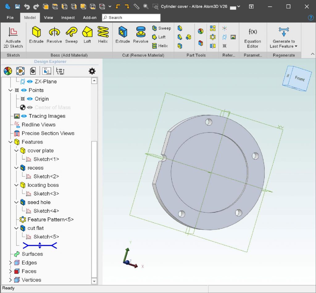
                                    Keep sketches simple – I strongly advise against having the cover outline and the holes in a common sketch. I'll send you a file with my own approach where you'll see I use multiple features, each with a very simple sketch. See image below – this approach keeps each step simple, and makes it much easier to edit a step (or even delete and start again) without throwing away all the stuff that did work.

                                    cover - explorer.jpg

                                    Extending your trial licence can be considered, but only if you accept help.

                                    #644400
                                    JasonB
                                    Moderator
                                      @jasonb

                                      David, my gut feeling about the dimensions "all laying on the axis" is simply down to Nigel just leaving the mouse where it is after clicking the second of the two items being dimensioned.

                                      I've done it here as I thing he is doing it, then repositioned them and then after removing the dimensions done it by positioning my mouse where I want the dimension befor entering it.

                                      Something that you could have spotted in an instant if connected to his machine

                                      #644406
                                      David Jupp
                                      Participant
                                        @davidjupp51506

                                        Jason, Thx.

                                        Nigel – dimensions appear where you place them.

                                        • Click item to dimension
                                        • (if appropriate click other item to dimension)
                                        • Move cursor to position dimension – click to fix position
                                        • Enter intended dimension value

                                        You can click/drag dimensions later to re-position.

                                        Edited By David Jupp on 08/05/2023 14:34:33

                                        #644418
                                        David Jupp
                                        Participant
                                          @davidjupp51506
                                          Posted by David Jupp on 06/05/2023 08:15:44:

                                          Nigel,

                                          It isn't just you – view cube is disabled for me in sketch mode. I can maybe see why that could be 'by design' but I'm not certain about that. I'll check with Alibre QA.

                                          Have just got the answer on this – unfortunately the View Cube (a 3rd party provided component) created a few issues with other tools in 2D sketch mode, so the decision was taken to disable it.

                                          #644430
                                          Nigel Graham 2
                                          Participant
                                            @nigelgraham2

                                            Jason, David –

                                            Thank you for that tip about dimensions.

                                            I'll open one of those drawings and try it…. It's the most basic of those cover drawings, just the outline circle and the first bolt hole.

                                            '

                                            Sketch mode on, Correct plane (XY) on. Cleared the Undo buffer by stepping back until the arrow turned grey.

                                            Select tool highlighted (blue background) but I can't select either circle. Clicking on them merely raises that summary tool-bar.

                                            The Dimension tool is OFF (pale grey).

                                            The Definition indicator says both circles are UN-defined in both magnitude and position. The main one is concentric with the displayed axis though.

                                            Can I dimension the circles? NO.

                                            Right, can I draw a line, anywhere? NO: Select 'Line', click somewhere on the image, nothing.

                                            Click on the axis though, and I can draw a line apparently at any angle but always starting at the origin. The cursor has that little crossed-out circle stuck to it – don;t know what that tells me.

                                            I drew two lines of set lengths, one along the X-axis, the other Y (by entering 90º ). The X-axis line is defined by magnitude but not position (yet it's on the axis and origin?); the Y-line is fully defined.

                                            Can I draw a line from their end nodes?

                                            Yes from the Y-one.

                                            Oh – the X-one is now shown as fully-"defined" (how did that happen?) and I can now draw a line from it.

                                            Something turned on Dimensions too.

                                            I've now a peculiar thing with two pairs of +ve and -ve going, straight lines of equal lengths, like steps, and a line joining the extreme ends, through the origin. I can't dimension that though, because it hits that "parametric" thing I know nothing about.

                                            I tried dragging the dimensions left on from drawing the first two lines, but could not move them. I only made them collapse onto the axis. Then found by selecting the Dimension tool again they jumped back to their original places.

                                            Dimension the circles? No. They are still Undefined.

                                            Let's try re-drawing the main circle….

                                            I should have really deleted the first but since I can't select it had to leave it. I've now a fully-defined new circle but the dimension I tried to place did not respond to my attempts to place it neatly. All I did was scrunch it up on the axis, and I could not click and drag any of the dimensions anywhere.

                                            .

                                            Finally, I tried to close it, which opens the Analyse menu. This revealed 27 faults, all but one being described as incurable! (Except by Nature giving the operator an IQ of 140 and learning ability to match…….)

                                            '


                                            Then you all wonder why I find the thing so difficult and frustrating: I can't make the simplest drawings..


                                            .

                                            I will re-iterate…

                                            ….. I do not denigrate the software!

                                            In fact of the three makes of CAD I have tried, Alibre seems the easiest to learn, at least to a fairly useful level even if I could never construct a 3D image of something like that engine on the publisher's own web-site. Or of my steam-lorry.

                                            It's me, not it, that has the problems. Perhaps I am physically unable to learn such software; just as I was unable to learn Mathematics or French, to play the piano, or be any good at sports and games. That is me, by Nature, not the programmers' fault, not some mysterious artefact of CAD!

                                            I do not refuse help. If that were the case I would not ask on here, let alone have accepted that offered tutorial last week. I don't though, want to impose on the publishers by asking questions that are just so basic as how to draw a line in the right place in one go every time.

                                            Edited By Nigel Graham 2 on 08/05/2023 16:06:45

                                            #644434
                                            David Jupp
                                            Participant
                                              @davidjupp51506

                                              Nigel – you don't actually appear to ASK here, you just give vague descriptions of your activities and the outcomes. Not clear enough to really work out what problem you are hitting. Not even any screenshots of any of the problems.

                                              Hopefully showing exactly what went wrong would lead either to you learning, or to Alibre being made aware of an unappreciated pitfall in use of the software.

                                              PLEASE send me for example your file with 27 errors in a sketch (tell me which sketch, to save time). There isn't an 'incurable' output – the 'heal' button can only address certain error types, for most the user has to resolve them. 27 faults suggests a 'busy' sketch. This is another reason why I strongly recommend the use of simple sketches – much easier to diagnose, and less work wasted if you do have to abandon a sketch.

                                              I don't see any big difference between asking for help here or directly from Alibre, or via the Alibre user forum.

                                              #644437
                                              JasonB
                                              Moderator
                                                @jasonb
                                                Posted by Nigel Graham 2 on 08/05/2023 16:05:21:


                                                Sketch mode on, Correct plane (XY) on. Cleared the Undo buffer by stepping back until the arrow turned grey.

                                                What you describe above is what is done to start a new sketch

                                                Select tool highlighted (blue background) but I can't select either circle. Clicking on them merely raises that summary tool-bar.

                                                You need to extrude the first sketch or rather than starting a new one right click the sketch down the left hand list and select edit

                                                You are trying to select items in a new sketch before you have added any and are just clicking away at the underlying previous sketch

                                                You need to do what David says and give him access to the files and screen shorts or even just a photo of the screen if you can't do a screen shot.

                                                Edited By JasonB on 08/05/2023 16:54:54

                                                Edited By JasonB on 08/05/2023 18:11:18

                                                #644439
                                                Ady1
                                                Participant
                                                  @ady1

                                                  He's not even getting to draw/sketch/edit mode, just clicking about randomly with select

                                                  #644441
                                                  JasonB
                                                  Moderator
                                                    @jasonb

                                                    I feel he is getting to sketch mode, can't be bothered to do a video to show it but I can replicate not being able to select what he thinks is in a sketch.

                                                    Also sounds like Ordinate dimensions has been clicked at some time hence the odd numbers. Again just problems with that odd mouse and not being used to using the new one.

                                                    I doubt it is coming up saying Parametric. The two options you get are Parameter and Driven when dimensioning a sketch

                                                    Edited By JasonB on 08/05/2023 17:13:43

                                                    #644443
                                                    Ady1
                                                    Participant
                                                      @ady1

                                                      Yes he's into sketch but only using select for everything

                                                      I've reached a point I really need get things down on paper – manually or by CAD – before wasting yet more metal, electricity and hours on endless re-working.

                                                      Nigel you're doing exactly the right thing by going for CAD in this situation btw

                                                      Edited By Ady1 on 08/05/2023 17:50:19

                                                    Viewing 25 posts - 176 through 200 (of 295 total)
                                                    • Please log in to reply to this topic. Registering is free and easy using the links on the menu at the top of this page.

                                                    Advert

                                                    Latest Replies

                                                    Viewing 25 topics - 1 through 25 (of 25 total)
                                                    Viewing 25 topics - 1 through 25 (of 25 total)

                                                    View full reply list.

                                                    Advert

                                                    Newsletter Sign-up