Alibre – A First Attempt

Advert

Alibre – A First Attempt

Home Forums CAD – Technical drawing & design Alibre – A First Attempt

Viewing 25 posts - 151 through 175 (of 295 total)
  • Author
    Posts
  • #643769
    David Jupp
    Participant
      @davidjupp51506

      Lee,

      Yes assembly constraints in Atom3D work the same as in Alibre Design (there are just some extra constraint options in Alibre Design Expert – for gears/pulleys/screw drives/racks).

      Both Alibre Design Professional and Design Expert offer a 'fastener' constraint – this speeds up placement of screws etc. by using a single constraint in place of the 2 constraints that would be required in Atom3D. You can achieve same result in Atom3D, just a bit slower to do.

      Aligned, Offset, Concentric, Tangent, Angle are available in all levels of the software.

      Edited By David Jupp on 03/05/2023 13:58:49

      Edited By David Jupp on 03/05/2023 14:00:21

      Advert
      #643772
      Ady1
      Participant
        @ady1

        That's why I got Alibre Atom, the assembly-movement function takes you to the next level and it works really well

        #643791
        Nigel Graham 2
        Participant
          @nigelgraham2

          David –

          Thank you clarifying that.

          .

          Martin –

          What would help? Goodness knows. I don't.

          '

          Jason –

          Got there eventually but what an exhausting, disheartening process (Image below).

          No of course I don't think that, but when trying to follow a tutorial exercise word for word so less likely to go wrong, it is very confusing and discouraging when you can't make things work or your results don't match as it leads you to expect.

          However, I was struck by your video apparently by-passing some of what the exercise test tells you, so I tried copying it and to my surprise I managed to assemble the clamp on the pole.

          So I tried putting the rest together. That was one monumental battle, at one point welding the thumb-wheel inside the clamp. I had to close and re-open the file to sort that out, and eventually succeeded, leaving a trail of at least 20 constraints and any number of "Undos" just in the second attempt at what an expert would doubtless knock off in ten minutes with no mistakes.

          .

          I noticed this though. The instructions, if I had read them right, say you put the parts on the screen, then select:

          Constraints > Enter the mating surfaces or edges > Constraint type (seems semi-automatic) > Apply > Close,

          and watch it slide with eerie grace into place; solid steel through solid steel like a ghost through a wall.

          Only, most of the time nothing happened, or it just aligned them in fresh air.. Finally, in desperation I grabbed the part to be added, and slid it by brute force and ignorance into place. It seemed to work, as if the Closed Constraints menu was still active out of sight.

          Whether the assembly is accurate is another matter. Aligning the collar and pin-holes was very difficult, as much by eye as by constraints that did not seem to do anything. I suspect if you could view it transparently you'd see the scriber has made the hole in the pin oval.

          As for what plane it's on…. More planet than plane. The two vertical planes are XY and YZ, the floor is XZ, and the little trident symbol was pointing anywhere but the normal, positive-going (x, y, z) directions. No idea why. I imagine you've no hope of depicting more complicated assemblies like engines or workshop machines, perhaps from sub-assemblies as well as individual parts, if you've no idea how to align the planes and orientations properly and coherently across all the drawings.

          '

          Oh, and I reverted to using the previous pointer despite it having no scroll-wheel, and this time everything seemed to respond as it should when selected.  

          '

          Learning 3D CAD to use to design engineering things to make? I'll be past making porridge by the time I manage to reach that level with CAD, if I ever do.


          PS: I don't sharpen my real scribers to such a long point! This one is a Chamfer set by guesswork after failing to make the Revolve Cut tool work.

          sc main assembly.jpg

          Edited By Nigel Graham 2 on 03/05/2023 16:48:22

          Edited By Nigel Graham 2 on 03/05/2023 16:51:30

          #643797
          JasonB
          Moderator
            @jasonb

            The parts may look like they are in mid air after adding a constraint but remember you are working in 3D THREE DIMENSIONS so will probably have to add an additional constraint or two to completely tie the component down into it's final position.

            Beware just dragging something into position as it may look right in a particular view but won't be in another. Also if a part is just dragged into position there is nothing to keep it there so you could find later when adding further parts and constraining them the part you dragged will move out of that position, not what is wanted

            Guesswork and your difficulty earlier positioning that random rectangle mentioned earlier can be solved by entering dimensions and constraining to an axis.

            #643799
            David Jupp
            Participant
              @davidjupp51506

              Nigel,

              The constraint interface has been updated since the MEW articles – there used to be a choice of 2 assembly constraint tools – they've now been combined into a single (improved?) tool that does look different. The new tool can access all the functions of the old, but some naming has changed slightly to simplify things.

              If applying constraints doesn't always work, it may be that something is wrong with your system/installation (I've offered to check this for you) – or you may be accidentally de-selecting, or even selecting a different item than intended. The constraint buttons that become active vary depending upon what is selected.

              Don't worry so about planes – whilst being consistent can be helpful, it isn't a requirement. I tend to just model my parts, then sort out the orientations when I assembly things (unless I design a part 'in context' whilst inside the assembly it will be added to).

              #643808
              John Hinkley
              Participant
                @johnhinkley26699

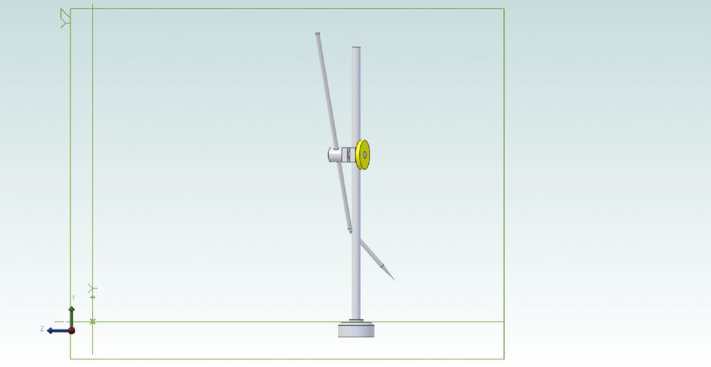
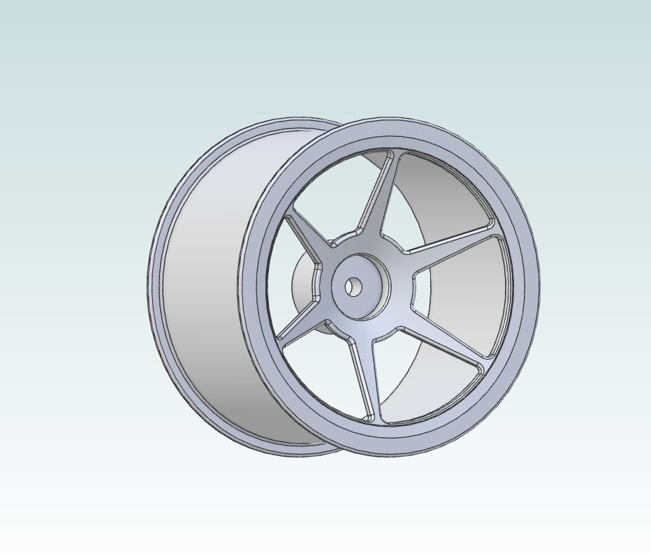
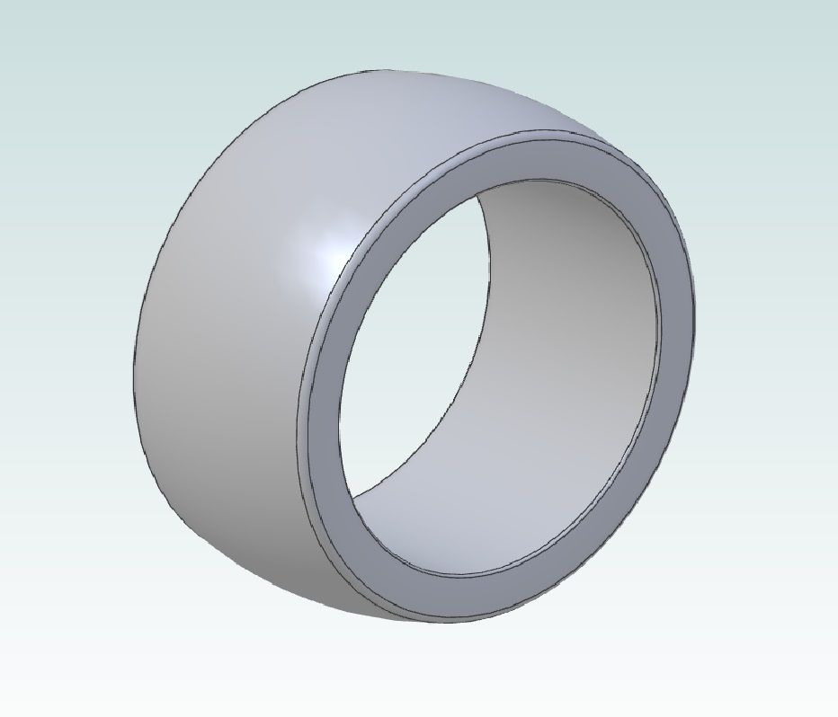
                I have been following this saga with increasing interest and growing frustration but have refrained from commenting until now. It would appear to me, Nigel, that you would be advised (by me, anyway) to decide what part is going to be the basis for your assembly – in this case I would suggest the base – and choose that as the first part in the assembly view, placing the centre of the base at the conjunction of all three axes. Then ANCHOR it there. You could always place it near the axes origin and use the constraints to locate it accurately. Then place the other parts into the drawing as if assembling them as you would in "real life" as it were. Constrain each part to the base and subsequent parts to their corresponding positions using as many constraints as necessary. Depending where I drop the part, I tend to align mating faces first followed by coaxial constraints. That way you build up the assembly and the end result is achieved in a sensible timeframe. For example, today I've decided to start the 3D modelling of a race car suspension, using bought-in wheels and tyres as the starting point.

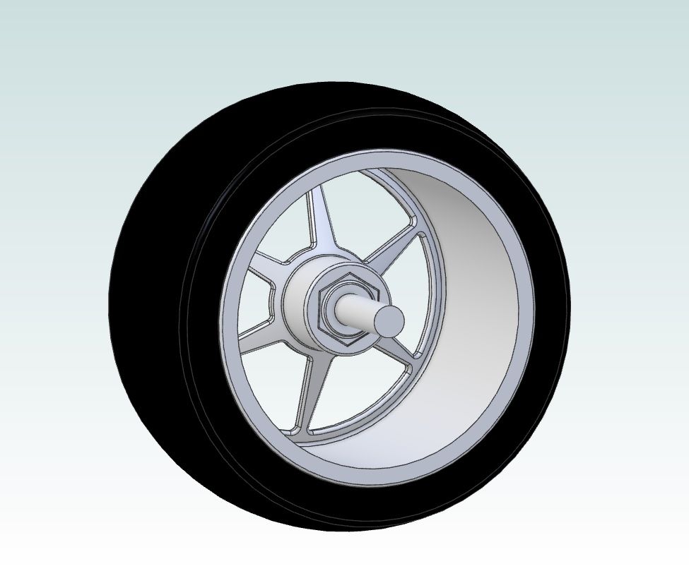
                This is progress so far. The wheel was placed in the assembly file and anchored to the axes conjunction, The tyre was then adde and finally the driveshaft.

                rear wheel tyre

                Wheel and tyre below as an assembly with the (unfinished) driveshaft as one.

                whole assembly_1

                Keep on plugging away, and take David up on his generous offer of help for goodness sake. I'm sure he'll get you sorted in no time, if only you'd give him the chance. Apologies if this advice is duplicating any already given. After 8 pages, I'm losing track of what has been said and what hasn't.

                Assuring you that his posting is made with the best of intentions,

                John

                #643815
                Nick Wheeler
                Participant
                  @nickwheeler

                  As above, you don't need the origin planes or axes to align/join parts. That's done using their own features(circle centres, edges, corners, whatever), with specific ones added just for that purpose if nothing appropriate exists already.

                  #643818
                  JasonB
                  Moderator
                    @jasonb

                    Part 2 of the article deals with the initial assembly and does exactly that inserting the base as the first part and than constraining it's position before adding the column. That is also exactly how I got the column and base in position before starting that latest video

                    Edited By JasonB on 03/05/2023 18:40:00

                    #643836
                    Ady1
                    Participant
                      @ady1

                      I always anchor the main body/base first and then bring in the parts

                      #643861
                      Nigel Graham 2
                      Participant
                        @nigelgraham2

                        Jason –

                        Yes, I know merely dragging parts about won't guarantee they will end up where they should but in this case they appeared to have been aligned as if the constraints still applied. The constraints tool seemed to place them in line on some hidden axis but not slide them along into place.

                        .

                        David –

                        It did seem to run a lot better with the new mouse replaced with the previous pointer, but yes, please test my installation. There might well be something flaky in that.

                        '

                        John –

                        Thankyou. I take your point about anchoring some key component. The exercise does in fact tell you to do that, then goes into a routine that aligns the Part's own planes with the Assembly plane. This gave me some peculiar results like flipping the part end-over-end.

                        #643884
                        JasonB
                        Moderator
                          @jasonb

                          A coaxial constraint won't slide the part onto the column. Just think about it and what I said about 3D. The two parts could be a mile apart and still have the hole lined up with the column (set in two axis). it is not until you set the third position that the clamp is completely constrained either by sliding it in that third axis as you did or setting it's position relative to something else like a plane or the base piece. As an example your tailstock barrel is concentric to the lathe spindle (one constraint) but could be anywhere along the bed, it is not until you move it along and lock it down that is is fully constrained.

                          The "flip" icon has been mentioned several times, use that if the part seems to be up the wrong way when the constraint is applied. Even gets mentioned in the article.

                          #643896
                          Nigel Graham 2
                          Participant
                            @nigelgraham2

                            Jason –

                            I understand that, but could not make the Constrain tool work fully (the most it did was align things on invisible axes), and failed to make Flip, flip anything at all.

                            As far as I can see I was using the "book" way, which seems either

                            ,

                            Case 1;

                            Bating faces looking in the same direction, outwards:

                            1) Rotate the images so both faces, on anchored part A and adding part B, are visible. Highlight these faces.

                            2) Open Constraint, select the A face then the B face as the tool's entry values.

                            3) Flip B by the double-arrow sign, so its contact face is now towards that on A.

                            4) Select 'Apply' and B should move onto A……

                            OR, Case 2

                            Both parts the right way round; only A face visible (image rotated if necessary, by a different isometric view).

                            1) Highlight the A surface.

                            2) Open Constraint, add that face to its entry form.

                            3) Rotate the image to show Part B's mating face.

                            4) Highlight that, add it to the Constraints form.

                            5) Select 'Apply'.

                            – and in either case, Apply makes B move onto A.

                            .

                            Shouldn't it? If I have that right, what stops it working?

                            I can't see any other way. Escher would have had great fun exploiting 3D CAD's propensity to create very strange effects by the slightest operator-error, but that doesn't help us put a simple engineering project together.

                            .

                            A further complication is shown by that scribing-block's clamp, pin and thumb-wheel. They need meet so the correct faces meet without combining the parts, and the holes and pin are all co-axial. So two constraints simultaneously, surely: 'co-incident' and 'co-axial'.

                            Assembling the scribing-block's thumb-wheel to the pin placed it centrally, inside the clamp and apparently part of it unless I managed to Undo it immediately. This centering works on something axially symmetrical like John's car wheel and tyre; but here we need an unsymmetrical result.

                            I tried to correct the misplaced thumb-wheel by dragging, by something I saw on the tool-bar, and called "Component Move" (I think), and by Undo. All failed but I was probably using "move" for the wrong purpose. This was where I closed the file to clear the mistakes, and re-opened it.

                            '

                            Some of Alibre's moves are not at all easy, and certainly not intuitive. As with a lot of advanced programmes, if you go wrong you obtain digitally-legal but totally wrong results, no change to the displayed data but an error-message comprehensible only to its programmer; or nothing happens at all. With no clue as to why.

                            #643909
                            Nick Wheeler
                            Participant
                              @nickwheeler

                              3D CAD would be a lot less frustrating for new users if it didn't allow you to MOVE, DRAG or ALIGN parts by wiggling them about randomly with the mouse. Then you'd have to learn to constrain/join/mate them properly using the relevant features in the parts. Like using the centre of the flat part of the thumbwheel, joined to the centre of the hole on an outside edge of the clamp – the two surfaces that on actual parts would bear on each other.

                              And turning off the display grid and its snaps should be the first thing to do before using the program.

                              #643944
                              JasonB
                              Moderator
                                @jasonb

                                Assembly of all the parts.

                                There is a lot more pulling about of parts, zooming in and out and flipping them about than is actually needed but done to show that although an initial constraint will set say the base hole and column co-axial they hand slide up and down and could be anywhere on the screen until the position of the end of the rod is constrained to the bottom of the base.

                                You will also see that when I add the screw to the block I can flip it from one side to the other and then set the hole to one side of the block it defaults to the hole ctr line so I use the offset option to set it half the hole dia away.

                                hen it comes to adding the thumb wheel that can be flipped but you can see it is also flipping the screw so I then fully constrain that by setting its end 5mm from the block's side.

                                Note Cosmetic screw threads as I used are not part of Atom but added to make it easier to see the parts being flipped about. Parts were drawn off the top of my head so may not be exactly as shown in article but have all the features needed.

                                Edited By JasonB on 04/05/2023 13:30:31

                                #643945
                                David Jupp
                                Participant
                                  @davidjupp51506

                                  Constraint limits (handy for letting clamp slide, but not beyond ends of column) are also not available in Atom3D.

                                  #643946
                                  Ady1
                                  Participant
                                    @ady1

                                    The assembly bit makes all the grind worth it Nigel, especially since you have credible movement

                                    Stick at it, keep your chin in and keep swinging

                                    #643948
                                    JasonB
                                    Moderator
                                      @jasonb

                                      One thing I do find helps both during assembly and earlier when 2D sketching is to try and click the item you don't want to move first and then the second one will move to it. That way even if the first item is not fully constrained it will generally stay put.

                                      #643951
                                      Nick Wheeler
                                      Participant
                                        @nickwheeler
                                        Posted by JasonB on 04/05/2023 13:48:52:

                                        One thing I do find helps both during assembly and earlier when 2D sketching is to try and click the item you don't want to move first and then the second one will move to it. That way even if the first item is not fully constrained it will generally stay put.

                                        Fusion works the other way, think join this to that.

                                        #644002
                                        Nigel Graham 2
                                        Participant
                                          @nigelgraham2

                                          Now don't go and confuse things even further, Mr. Wheeler!

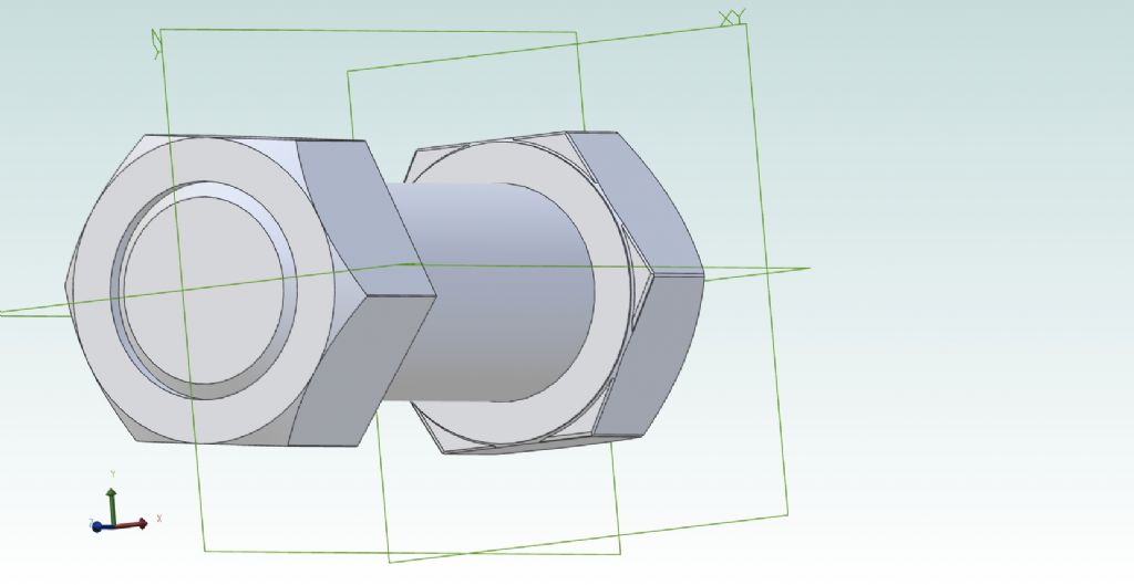
                                          m25 nut + bolt.jpg

                                          Finally took the plunge and had a tutorial with David Jupp today, so thank-you for that.

                                          To see how much had sunk in I tried drawing a nut and bolt based on ones I have sitting on the kitchen window-sill, obtained for I forget what! I thought from quick measuring by rule that they are M25 but the standard size is really M24 – I am not going to worry about that here!

                                          I set out to try to crack that Revolve Cut thing to make the top chamfers on the nut and head, helped by going right back to Jason's video. It worked, but I still found it difficult. The underside chamfers are just that, Chamfers.

                                          I tried the threads, using values from the Zeus book that I keep by the PC, but they defeated me.

                                          .

                                          I realised the less efficient way is to draw the nut with hole in one go. By drawing it with no hole then making a copy on its own file, one can become the bolt head and then you can turn the other into the nut, but never mind. It was a second go at the Revolve Cut tool!

                                          .

                                          The two are separate Parts so if I feel up to trying to give them threads, I can. I forgot about aligning the two sets of planes and had a bit of a fight with that Flip tool to make the nut face the right way on the bolt, but then constrained the two together by end faces. I see the two are slightly out of angle, by the hexagons.

                                          '

                                          I am now fairly certain that new mouse I tried was giving me gyp, but the Escape key is also a bit slow at times, needing two or three goes. David showed me the view-cube but is there a way to keep it on the screen? It seems very fussy when it will be available when going back and forth between Sketch and Model, and I couldn't determine when.

                                          #644003
                                          lee webster
                                          Participant
                                            @leewebster72680

                                            Making progress Nigel.

                                            Apart from your progress I am also impressed with the amount of attention your post has attracted, and the help offered. I have visitors coming to stay this week, but when they have gone home I will download the trial of Atom 3D so I can assess it for myself. I must say I am looking forward to it.

                                            #644007
                                            JasonB
                                            Moderator
                                              @jasonb

                                              Once turned on the View cube which was not available at the time of the article should come up on any new part modelling screen and stay there until turned off via the view tab. Once turned off it will not come up again on any file new or old until turned back on.

                                              The only time you may not see it is is a dialogue box like constrain, mirror, circle pattern is opened and happens to obscure it. All you need to do is hold the right mouse key down on those boxes and drag them to somewhere else on the screen

                                              #644008
                                              David Jupp
                                              Participant
                                                @davidjupp51506

                                                Nigel,

                                                To get angular alignment of nut and bolt head, one option of several is to use 'show reference geometry' for the nut – then you can use its reference planes to constrain to assembly planes.

                                                Another option (if nut and bolt head are same AF size) is constrain 2 flats to be aligned.

                                                If they are not the same AF size, constrain flats parallel – that is 'offset' with the 'free' option chosen.

                                                Or set an angle between 2 flats (be that zero, or some other).


                                                Edited By David Jupp on 05/05/2023 07:41:29

                                                #644011
                                                David Jupp
                                                Participant
                                                  @davidjupp51506

                                                  Modelling physical threads. This can be done either by cutting material away (as shown in the MEW series) or by adding material on.

                                                  The most common problem I see is that the profile sketch used for the thread is wider than or equal to the thread pitch. For the helical tools to work well, the profile width (along the helix axis) should be less than the pitch (only needs to be slightly less). If needed, rounding of thread crests can be done afterwards using a fillet.

                                                  Another common issue getting helical tools to work is if the profile sketch is not on an appropriate plane, or difficulty selecting the axis for the helix.

                                                  If a particular task eludes you – open a support ticket with Alibre (and attach your file) the team at support will be happy to help.

                                                  #644132
                                                  Nigel Graham 2
                                                  Participant
                                                    @nigelgraham2

                                                    Thank you.

                                                    I seem to find the View Cube a bit more elusive than that. It seems to be on or off depending on which screen you are on, sketch or model, and I've not fathomed out what switches it off again.

                                                    I also spent a while this evening trying to put a thread on that bolt shank.

                                                    I tried using the instructions in the tutorial, with the dimensions adjusted, but kept failing to make the profile. This seems very hard for any sort of revolved cut, and threads just add more complexity. Often I cannot even make the Line tool draw a line.

                                                    Perhaps I'll leave threads and concentrate on more important aspects. I don't usually draw threads fully for standard fasteners anyway, though it is important to consider the sizes of nuts and bolt-heads, and room for spanners. I would rarely if ever need design a thread or a spring; but there are many possible uses for the revolved cut tool.

                                                    #644138
                                                    David Jupp
                                                    Participant
                                                      @davidjupp51506

                                                      Nigel,

                                                      It isn't just you – view cube is disabled for me in sketch mode. I can maybe see why that could be 'by design' but I'm not certain about that. I'll check with Alibre QA.

                                                      If you are still having problems with revolve cut, for thread or anything else, send me a part file where you have failed (don't delete your attempts) and I'll take a a look.

                                                    Viewing 25 posts - 151 through 175 (of 295 total)
                                                    • Please log in to reply to this topic. Registering is free and easy using the links on the menu at the top of this page.

                                                    Advert

                                                    Latest Replies

                                                    Viewing 25 topics - 1 through 25 (of 25 total)
                                                    Viewing 25 topics - 1 through 25 (of 25 total)

                                                    View full reply list.

                                                    Advert

                                                    Newsletter Sign-up