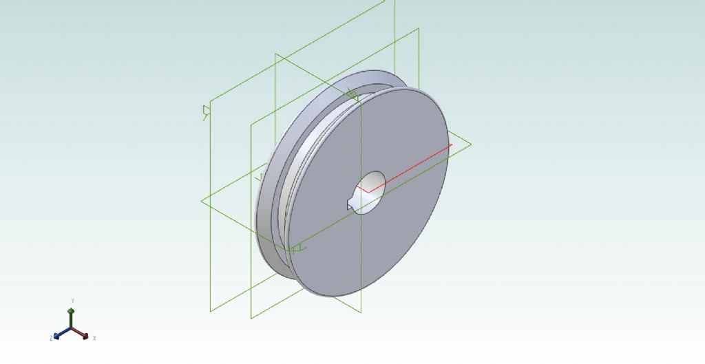
This was one of my own attempts. The groove is a bit unsymmetrical, and any resemblance to any real Vee-belt size living or dead is purely coincidental. Oddly though I managed to make that Revolve Cut tool work on this, but not at all in the tutorial exercise.

Just spent half the morning fighting my way through that MEW tutorial to draw a scribing block.
I'd already fitted the column to the base, but with a parallel rather than tapered fitting.
So this morning, I've completed the parts but omitted the two threads and the knurling. In fact the text suggests the threads impose a huge overhead on the system, and to use a note on the 2D drawing instead: the convention of course is a thin rectangle to show the thread, and a dimension-note. I judged it too difficult anyway.
'
The scriber-point is meant to be drawn as was the column taper – a "Revolved Cut". That kept failing as well, with every attempt raising error-messages the user is presumed to understand. To Hell with it then: I created it as a long chamfer.
Something I found too, was where you are meant to enter a value for some features, it won't let you. You have to scroll or step through a counter instead. The Escape key is not always very prompt either, needing several presses. Could be a keyboard fault but I'd be surprised on a unit only about a year old.
I did though discover how to draw two lines of set length at a set angle directly, in this case for the scriber's centre-line; using the inside angle [180 – external] rather than by dimensions afterwards. (There's a proper mathematical name for that type of angle, but I have long forgotten it.)
.
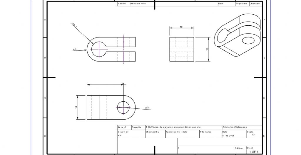
It has you produce an orthographic drawing for the Clamp. That went moderately well but I was unable to dimension the width of the slot, nor to add the overall length dimension in the way it describes. It tells you to dimension the width next to the radiused end, and a special slot-dimension menu will appear. Oh no it didn't.
The little rendering is all at some peculiar angle of its own, as well, as the image below shows.
I had picked ISO which gives First-Angle projection but the menu also mentions something called "J-ISO" or something like that, and ANSI. I know ANSI is American but the 'J' one is new to me. Is that also American?
There might be a way to carry the colour over into this drawing's rendering, but I didn't see it, and it's not that important here!
.
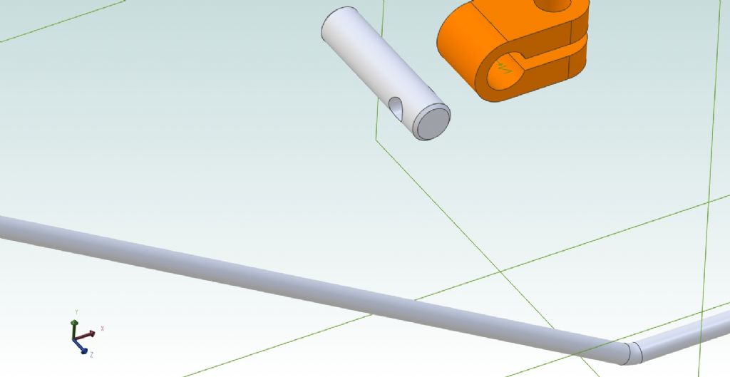
I've now an Assembly drawing with five separate parts, none in the orientations shown in the instructions, and I can't find anything that will rotate them individually. The clamp is lying on its side, for a start.
Trying to align the two pairs of planes is a nightmare. It kept doing all sorts of strange things. The text says three pairs but the display had only two pairs plus one plane on its own. The text also refers to a 'Flip' command under Assembly Constraints, to turn individual parts the right way up, but wherever it really is, is not there!
I was unable to reduce the started assembly drawing enough to show all the parts. I thought I had done, but clearly not.


lee webster.


