Alibre – A First Attempt

Advert

Alibre – A First Attempt

Home Forums CAD – Technical drawing & design Alibre – A First Attempt

Viewing 25 posts - 251 through 275 (of 295 total)
  • Author
    Posts
  • #644647
    lee webster
    Participant
      @leewebster72680

      Martin,

      The drawing you did with the rectangle and circle, would work in DesignSpark mechanical. DS makes each part of the sketch into a surface, the rectangle and two halves of the circle could be either extruded into a solid, or extruded as a cut. That's why I was unsure about Alibre.

      Advert
      #644811
      Nigel Graham 2
      Participant
        @nigelgraham2

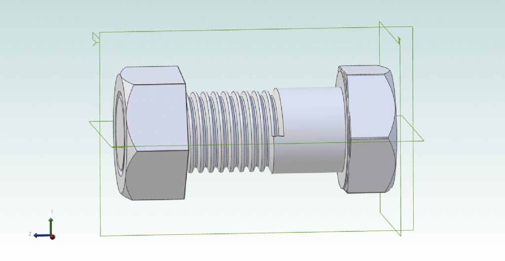
        Had another go at the Revolved Cut tool to see if I could cut a thread….

        It's not an easy tool to use though the scribing-block exercise says it is.

        The nut is still plain, but after a lot of mistakes, puzzlement, referring back to the tutorial document and experimenting I managed to make something looking like an M25 thread on the bolt. I've over-rounded the crest a touch but at least I managed to round it off.

        (I had based this exercise on rule-measuring an M24 nut and bolt I have lying about. I found later that the actual ISO standard is indeed M24 not M25, but don't tell anyone I'd not looked at the thread-charts first.)

        m25 nut + bolt.jpg

        #644815
        JasonB
        Moderator
          @jasonb

          You are getting theresmiley

          #644832
          John Hinkley
          Participant
            @johnhinkley26699

            Well done, Nigel. Keep up the good work.

            John

            #644969
            IanT
            Participant
              @iant

              I've just had a very weird experience. Needed to revisit some old TurboCAD work I did many years ago. However, I didn't have TC loaded on my new laptop. So I dug out the USB stick with my TC16 stuff on it and (finally) found the email from Mr Tracy with the serial number and actvation code. All loaded OK and then up popped a window asking if I'd like the available update? Thought it might be a good idea, so downloaded that. All good – fired it up and….

              I have no idea what I'm doing – it's like I'm looking at a completely alien CAD system. First, it seems to have defaulted to 3D mode (I don't remember that at all) and second – I've forgotton eveything I thought I knew so well about TC (after using it for some 20+ years! ) . I'm sure it will all come back but (after 3 years away) all I want to do right now is run back to Solid Edge as quickly as possible.

              (Sorry – back to Nigel's Alibre adventures)

              IanT

              #644982
              lee webster
              Participant
                @leewebster72680

                I too have now installed the trial version of Alibre Atom3D Nigel. At least I can now follow along with what you are doing.

                #644999
                Nigel Graham 2
                Participant
                  @nigelgraham2

                  Thank you Jason, John.

                  .

                  Ian – I think 3D is TurboCAD's default mode, probably because all its rivals are. It seems now the de facto CAD way; although CAD advertising shows still a strong professional market for 2D programmes.* You can still switch to 2D mode in TurboCAD – never switch in mid-drawing – certainly in TC 2021 Deluxe, which I have.

                  TC offers saving files in common CAD formats like DWF, and it is possible to transfer its 2D drawings into Alibre, presumably SE too, with the specifically-TC formatting bits rermoved. I have not yet found how to do it so they act as ready-made Part sketches; and I don't know about transferring 3D drawings.

                  .

                  It is very different from SoldEdge and Alibre though, especially in 3D mode which in TC has at least two solid types ("solid" and surface). The other makes appear to tuck all that neatly away behind the screen – so saving we poor users what I've always found TurboCAD's biggest 3D headache!

                  Also be aware that IMSI does seem to change individual tools around from edition to edition, not just bung in more, and each edition has three different versions (Deluxe, Professional and Platinum) different by each step up offering more tools anyway. Deluxe is the rather disigenuously named basic version. So its primary functions should all still be there but you might need ferret some out: why leave a tool easily accessible when you can change its symbol and hide it to baffle users? Still, TC does that very useful toolbars and commands library, and I have often used it.

                  .

                  Lee –

                  Good luck! What I found frustrating, and it is by no an Alibre problem, is the tutorials and general manuals don't warn you what can go wrong if you make a mistake or miss a step. So when you hit an obstacle you don't know where you went wrong.

                  On the other hand I like its Parts and Assembly modus operandii. It gives natural breaks to the process, but more importantly perhaps, if you go wrong drawing one new Part, you won't hurt the rest.

                  Also I like the way modifying a Part, including correcting errors in it, is reflected in the Assembly – with the proviso of due care and diligence in the Assembly's design, which is not a CAD matter.

                  Presumably, if you think you may need reverse the change, one would store the Part as two separate files suitably named, keeping the original intact; but I don't know how you break the Assembly link to the first used.

                  Whilst I'd not expected adding a repeated Part to an Assembly to be as simple as one mouse click per copy. That was a very pleasant surprise! My two generic CAD books, and TurboCAD, all work on complicated Groups and Blocks for things for that. Alibre seems to take care of that internally.

                  '''''

                  * Still a market too, for manual drawing-boards, and slide-rules! (All right, the latter are specialist trade ones, not ordinary times-sums tools.)

                  #645004
                  David Jupp
                  Participant
                    @davidjupp51506
                    Posted by Nigel Graham 2 on 13/05/2023 10:27:46:

                    Presumably, if you think you may need reverse the change, one would store the Part as two separate files suitably named, keeping the original intact; but I don't know how you break the Assembly link to the first used.


                    Nigel – be VERY careful here – it can all be done, but it's also easy to mess things up badly.

                    If you change the name of a part file outside of Alibre, this can have dire consequences. Use 'Save As' from inside Atom3D if you want to save a version of the file for archive/fall-back, or to edit it to produce a variant of the design.

                    For an explanation see this help topic

                    In Atom 3D, if you need to substitute one part for another in an assembly, you have to delete one and then insert/constrain the other. In higher levels of the software there is 'replace component' tool that can make this a bit easier to achieve.

                    Edited By David Jupp on 13/05/2023 11:14:48

                    Edited By David Jupp on 13/05/2023 11:15:08

                    #645011
                    Nigel Graham 2
                    Participant
                      @nigelgraham2

                      Thank you David.

                      I had assumed saving copies within Alibre, but didn't know how you replace one Part with another version of itself in an existing assembly.

                      Another question, outside of actually using Alibre…

                      My trial licence ends in the next few days. What happens then: does Mintronics send an invitation to buy? I looked on the Alibre web-site but couldn't find anything about that.

                      #645013
                      IanT
                      Participant
                        @iant

                        How do I switch 3D "Off" Nigel? Looked last night but couldn't find it… (have to relearn my TC keyboard shortcuts again too). Part of problem is that I'd customised/simplified the TC UI quite a bit and cannot remember everything I did now (TC on my old laptop looks quite different to this 'reloaded' one)

                        I will be moving some of my 2D to SE – hence the need to tidy things up a bit before doing so…in a bit of a rush at the moment but I've certainly done this in the past.

                        Regards,

                        IanT

                        #645016
                        David Jupp
                        Participant
                          @davidjupp51506
                          Posted by Nigel Graham 2 on 13/05/2023 12:16:39:

                          My trial licence ends in the next few days. What happens then: does Mintronics send an invitation to buy? I looked on the Alibre web-site but couldn't find anything about that.

                          Typically the Sales channel for your region will follow up in one way or another. If that doesn't happen for any reason you can of course initiate contact.

                          At the follow up contact, it's a good idea to ask about any remaining concerns/uncertainties before you make any decision.

                          #645025
                          Nigel Graham 2
                          Participant
                            @nigelgraham2

                            Ian –

                            TurboCAD's 2D/3D mode switch toggles between them, and is called Toggle 2D/3D.

                            It does not turn them off as such. A TC drawing is one or the other according to how you start it, so you must never use that control on an active drawing, in either mode. If you do it plays havoc with the co-ordinates and work-plane system for the drawing, and from the TC Users' Forum I gather more people come to grief on that than anything else!

                            It is a small, rather obscure button likely to be along the bottom between the Inspector Bar and the co-ordinates meter, and its symbol is a plain square and a wireframe cube with a '/' sign between them.

                            Next to it in in 2D is a button with a finger on a square, called Selector 2D Properties. This shows what aspects of the drawing field are on or off.

                            I have not investigated it but I suspect if you want to transfer a 3D drawing into another package to become a 2D generating Sketch you'd certainly need use the viewing cube function. You might also need go via Viewports to give 2D elevations, and Save As those as appropriate.filetype. (Find out what standard types SE wants, then look to see if TC offers those types.)

                            Don't try using Toggle 2D/3D. I think that could just wreck the drawing, as a TurboCAD 3D drawing is not simply a set of extruded sketches, and its generated solids come in two flavours with different properties.

                            Best to experiment on a harmless copy under a new name before risking losing anything!

                            .

                            Don't worry too much about keyboard short-cuts. They make life more efficient, but are not essential.

                            .

                            Thank you David.

                            I will wait patiently….

                            Remaining concerns.

                            I think my main one is knowing when not to use Grid Snaps and when I should.

                            #645026
                            David Jupp
                            Participant
                              @davidjupp51506
                              Posted by Nigel Graham 2 on 13/05/2023 14:06:16:

                              Remaining concerns.

                              I think my main one is knowing when not to use Grid Snaps and when I should.

                              Personally I would say NEVER use Grid Snaps.

                              I have come across woodworkers for example, who work on the basis that all measurements are multiple of 1/4" or 1/8", and they only ever use right angles, so they find grid snaps can speed up their sketching. Grid snaps do allow you to be rather lazy about defining dimensions, as you are unlikely to accidentally drag a line end (say) away from a grid snap. Maybe helps with making sure lines ends meet, but the non-grid snaps can also do that.

                              As you've found snaps can cause unexpected problems – so I'd turn them off. If you do come across a case where you decide they'd be really beneficial, you can turn them back on for that project.

                              #645070
                              Nigel Graham 2
                              Participant
                                @nigelgraham2

                                Thank you David. That's cleared my confusion over those!

                                #645102
                                SillyOldDuffer
                                Moderator
                                  @sillyoldduffer
                                  Posted by David Jupp on 13/05/2023 14:18:11:

                                  Posted by Nigel Graham 2 on 13/05/2023 14:06:16:

                                  Remaining concerns.

                                  I think my main one is knowing when not to use Grid Snaps and when I should.

                                  Personally I would say NEVER use Grid Snaps.

                                  As you've found snaps can cause unexpected problems – so I'd turn them off. If you do come across a case where you decide they'd be really beneficial, you can turn them back on for that project.

                                  I wouldn't go so far as to say NEVER, but my experience on other 3D-CAD software is that grid-snaps are mostly counter-productive. They're much more useful in 2D-CAD, where it often doesn't matter whether or two lines join correctly as long as the drawing looks OK to the human eye. 3D-CAD is different; it's vital that lines join correctly, because solids can only be generated from valid 2D loops.

                                  Snaps automatically create or enforce accurate connections of various types. Worth practising for an hour or two with them to understand when they're useful, and when they're not. Snaps are tools, and using the wrong tool by accident always causes trouble. Most software does a good job most of the time selecting the appropriate snap automatically, but not always. The operator may have to override the computer's choice.

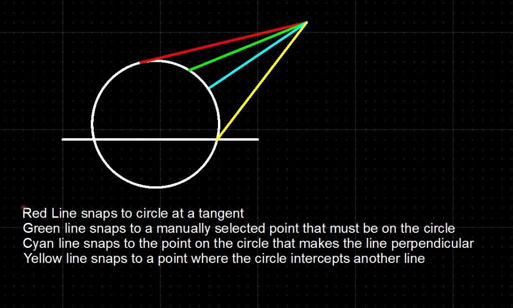
                                  This example from QCAD illustrates 4 different ways a line might be snapped to a circle. QCAD offers a few more, but the point is which of several snaps is correct depends on what the operator is trying to achieve. If the software makes the wrong choice one or more times and the operator doesn't notice, his sketch won't do what the operator expects, no matter how good it looks!

                                  snapexamples.jpg

                                  All CAD tools allow the operator to control which snaps, if any, are active. For example, when a line has to join a circle at a tangent, which can be tricky, it's useful to temporarily turn all the other snaps off. Doing so ensures the line can only join correctly at a tangent, and not just look like one!

                                  Zooming in on sketches is one way of detecting otherwise invisible connection errors. When CAD tools refuse to work, despite everything looking right, it's often because the sketch has a tiny mistake, perhaps because the wrong snap engaged. Snapping to the grid caused me more trouble than all the other snaps put together, but it's well to understand other snaps can also cause trouble.

                                  Snaps are simple enough once understood, but have the potential to cause much confusion. On a drawing board, the draughtsman has to know how to draw tangents. A computer deskills tangent drawing by creating them with a few clicks, but the operator has know when to tell the computer exactly which snap is required when there's any ambiguity.

                                  Dave


                                  Edited By SillyOldDuffer on 14/05/2023 12:16:11

                                  #645104
                                  JasonB
                                  Moderator
                                    @jasonb

                                    Have you never had the need to send a DXF or DWG file off to anyone Dave? in those cases it DOES matter if the lines join crrectly.on your 2D. Even if just for your own use if lines don't meet and you use thos elines to produce working 2D drawings what will the computer put as the dimension? the drawn line length or the length of the line it is meant to meet up with.

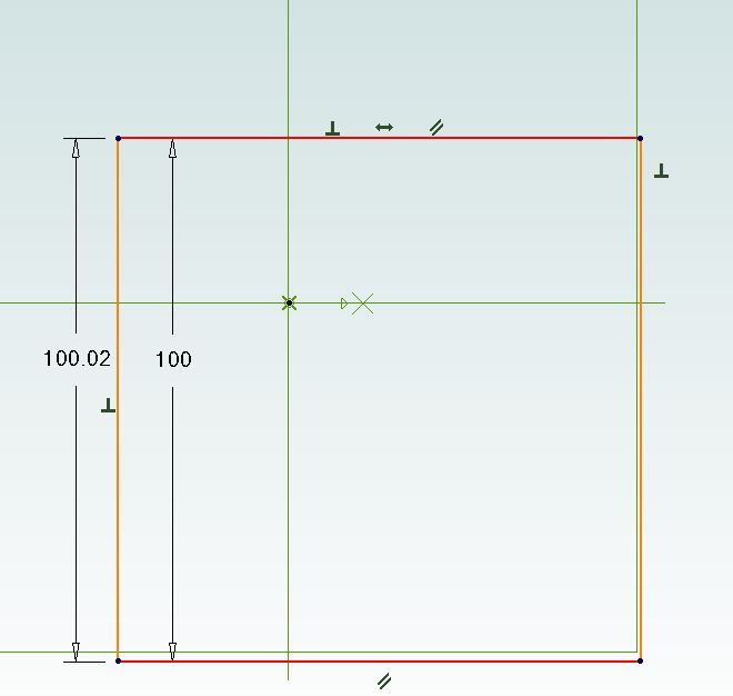
                                    This is a square of equal sides, 90deg corners but the line on the left was drawn a bit longer depending on wher you click to generate the dimension you may get the 100mm of the squares side or the 100.02 of the line

                                    lines.jpg

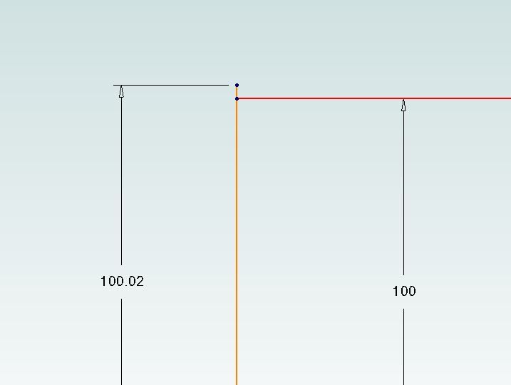
                                    Only by zooming right in can the difference be seen, may be OK for you in the "near-e-nuff" workshop but could affect which way your pendulum swingswink 2

                                    lines2.jpg

                                    I like to be the one designing not letting the 'puter put the lines etc where it wants so never use the grid or snap to it.


                                    Edited By JasonB on 14/05/2023 12:31:34

                                    #645117
                                    David Jupp
                                    Participant
                                      @davidjupp51506

                                      As I've said before – no single 'correct way', and people have their own preferences.

                                      The question related specifically to Atom3D, where toggling grid snaps on/off requires a diversion into System Options, it isn't easily doable from the workspace.

                                      The question was also specific to GRID SNAPS, not other types of snap.

                                      #645390
                                      lee webster
                                      Participant
                                        @leewebster72680

                                        Hi Nigel,

                                        Any progress with Alibre? I tried it for a few days, and as good as it is, it isn't for me, so I have un-installed it. I will continue to do my main work with Design spark, and wander into Solidedge when I need serious text design.

                                        Good luck.

                                        #645404
                                        blowlamp
                                        Participant
                                          @blowlamp
                                          Posted by lee webster on 16/05/2023 16:48:49:

                                          Hi Nigel,

                                          Any progress with Alibre? I tried it for a few days, and as good as it is, it isn't for me, so I have un-installed it. I will continue to do my main work with Design spark, and wander into Solidedge when I need serious text design.

                                          Good luck.

                                          Shame about that Lee. It's never easy finding the thing that suits you best.

                                          You have got me wondering what you'll be doing in Solidedge with regard to text design though – something like nameplatesquestion

                                          Martin.

                                          #645409
                                          JasonB
                                          Moderator
                                            @jasonb

                                            That nice Austin logo probably

                                            #645410
                                            lee webster
                                            Participant
                                              @leewebster72680

                                              Martin,

                                              Solidedge is very good at text manipulation. I was surprised at what it could do, so yes, nameplates mainly. If it's just plain extruded text with draft for casting, then Designspark can do that. I didn't get into text with Alibre. I could see why so many recommend the programme though.

                                              Lee.

                                              #645432
                                              David Jupp
                                              Participant
                                                @davidjupp51506

                                                Text tool in Alibre Design / Atom3D is relatively basic. There are some extra abilities being added for the next release due later this year. Should help with doing things more complex than straight lines of text.

                                                #645434
                                                JasonB
                                                Moderator
                                                  @jasonb

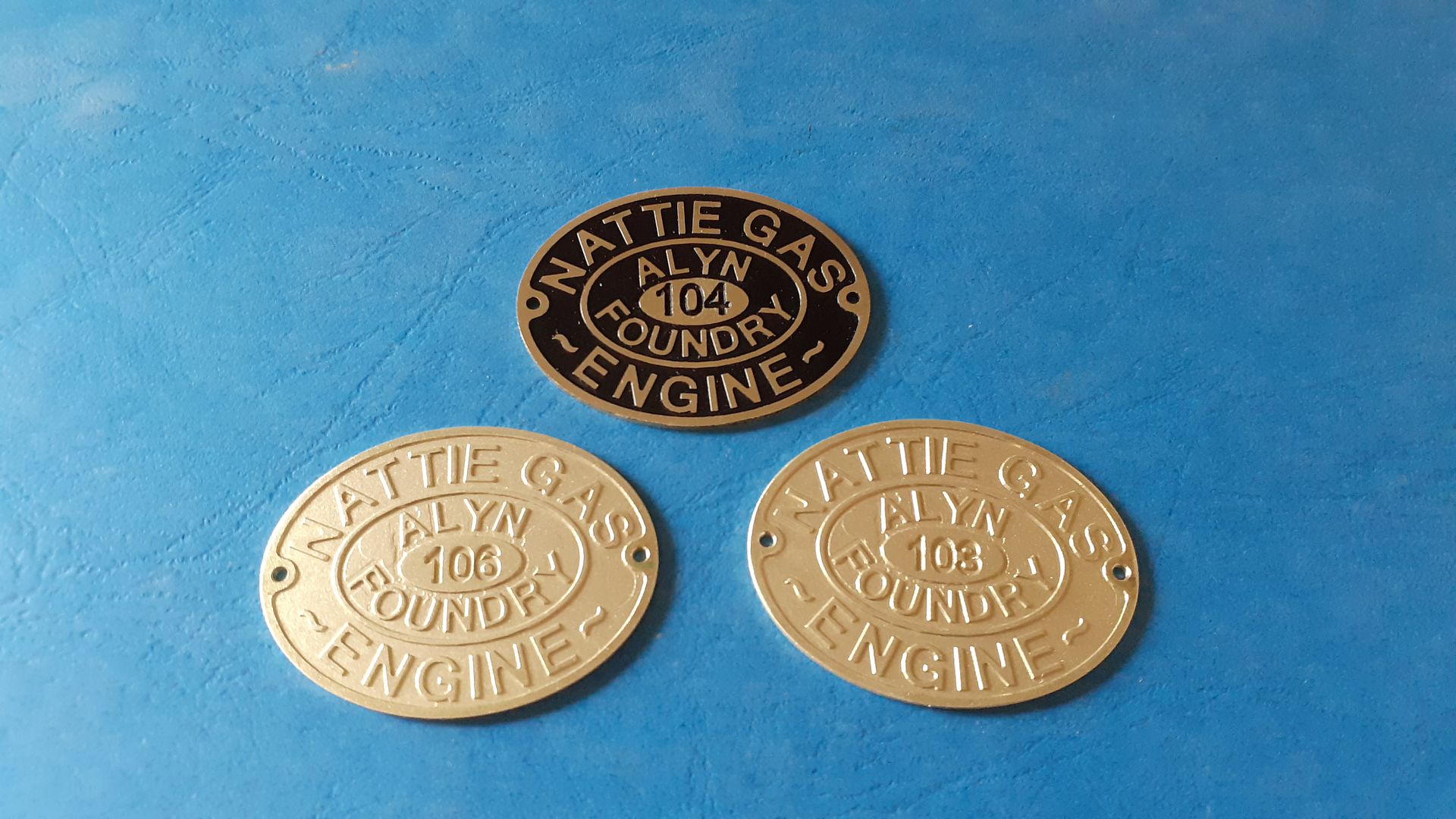
                                                  That will come in handy if I have any more like this to do

                                                  #645437
                                                  lee webster
                                                  Participant
                                                    @leewebster72680

                                                    Those name plates are excellent Jason. Very difficult to do in Designspark, but a bit easier in SolidEdge. What programme did you use?

                                                    #645440
                                                    JasonB
                                                    Moderator
                                                      @jasonb

                                                      Alibre what else!

                                                    Viewing 25 posts - 251 through 275 (of 295 total)
                                                    • Please log in to reply to this topic. Registering is free and easy using the links on the menu at the top of this page.

                                                    Advert

                                                    Latest Replies

                                                    Viewing 25 topics - 1 through 25 (of 25 total)
                                                    Viewing 25 topics - 1 through 25 (of 25 total)

                                                    View full reply list.

                                                    Advert

                                                    Newsletter Sign-up