Thank you.
Jason –
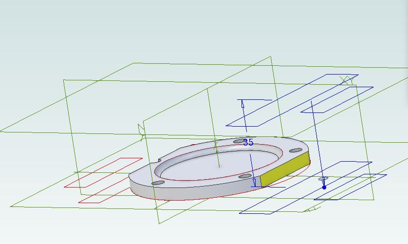
Ah, not the PCD. That is fixed by needing to place a stud centrally in a web only 5/8" thick. What is variable is how many holes, but whether 5 or 6 studs, the cover's own PCD is still to that central stud.
The effect is important at the outer ends too, as it dictates the size and layout of the steam passages to avoid fastenings going though them.
This raises an aspect of CAD I learnt at work, even before trying it for the first time myself. You still need know designing things even though CAD lets you draw them efficiently, and examine how their assembled parts interact.
.
David –
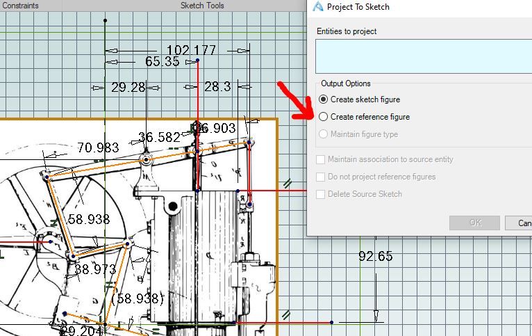
I'd not realised how deeply the matter of the grids and dimensions go. I remembered the term "parametric" as a type of equation – though did not understand them – so did not know if Alibre's meaning is part of the software's internal mathematics or is more immediately related to what the user sees and does.
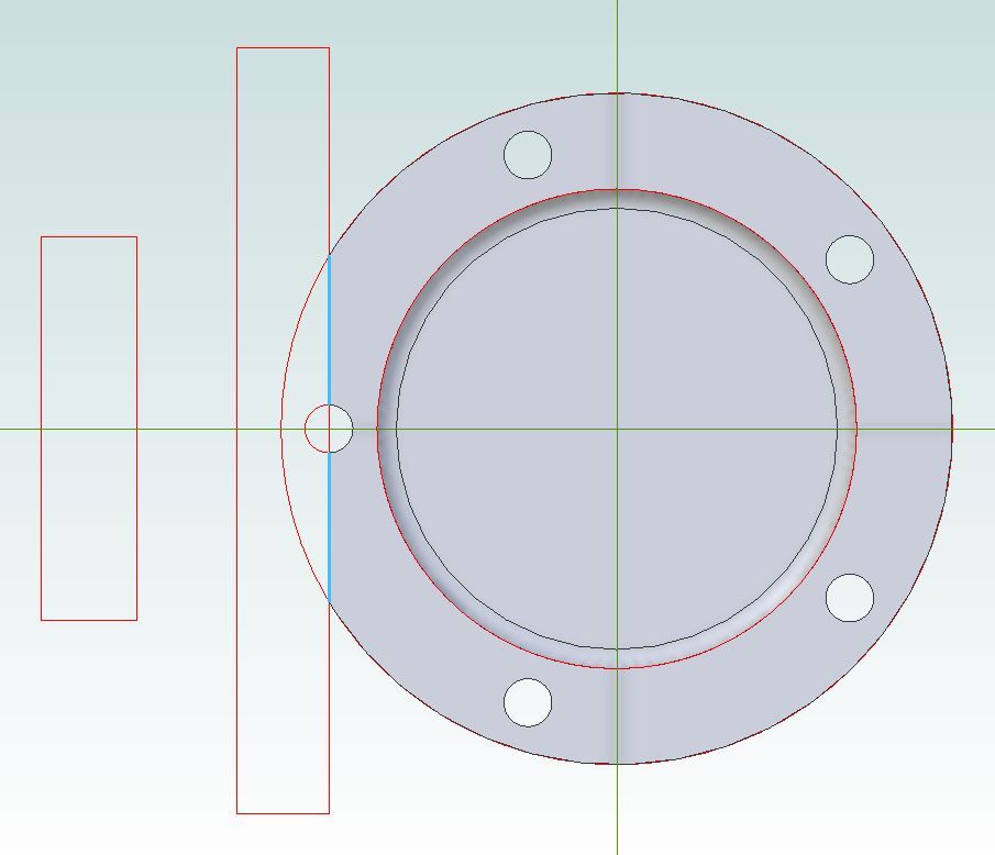
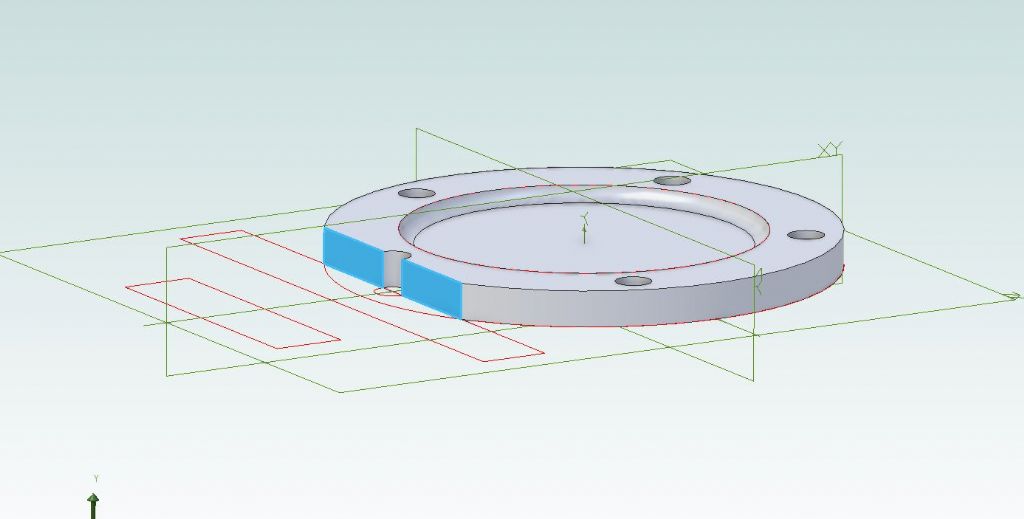
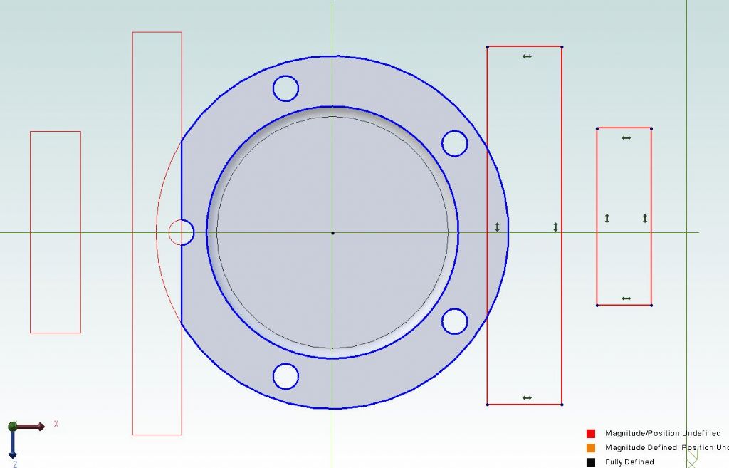
I'd had a fright when seeing how that revolved cut cut goes about its business – the momentary swarm of triangles is a bit alarming – but I had noticed making the generating shape needs a planar elevation. My first attempt put the taper triangle at a strange angle to the outline, as I had a tilted view still on, but setting the column upright solved that.
I have come across IT terms not always matching the words' ordinary meanings, elsewhere, with MS 'Access' the worst offender; but it tends to make the software less intuitive.
.
When I tried learning TurboCAD's 3D mode I'd often create single-topic exercises to examine individual tools – holes through rectangular blocks, and the like. Whereas CAD tutorials put a lot of action into a small space, so can look overwhelming for someone who finds complicated software hard to learn; and that deterrent effect can be reinforced by the impressive, rendered images on the publishers' web-site.
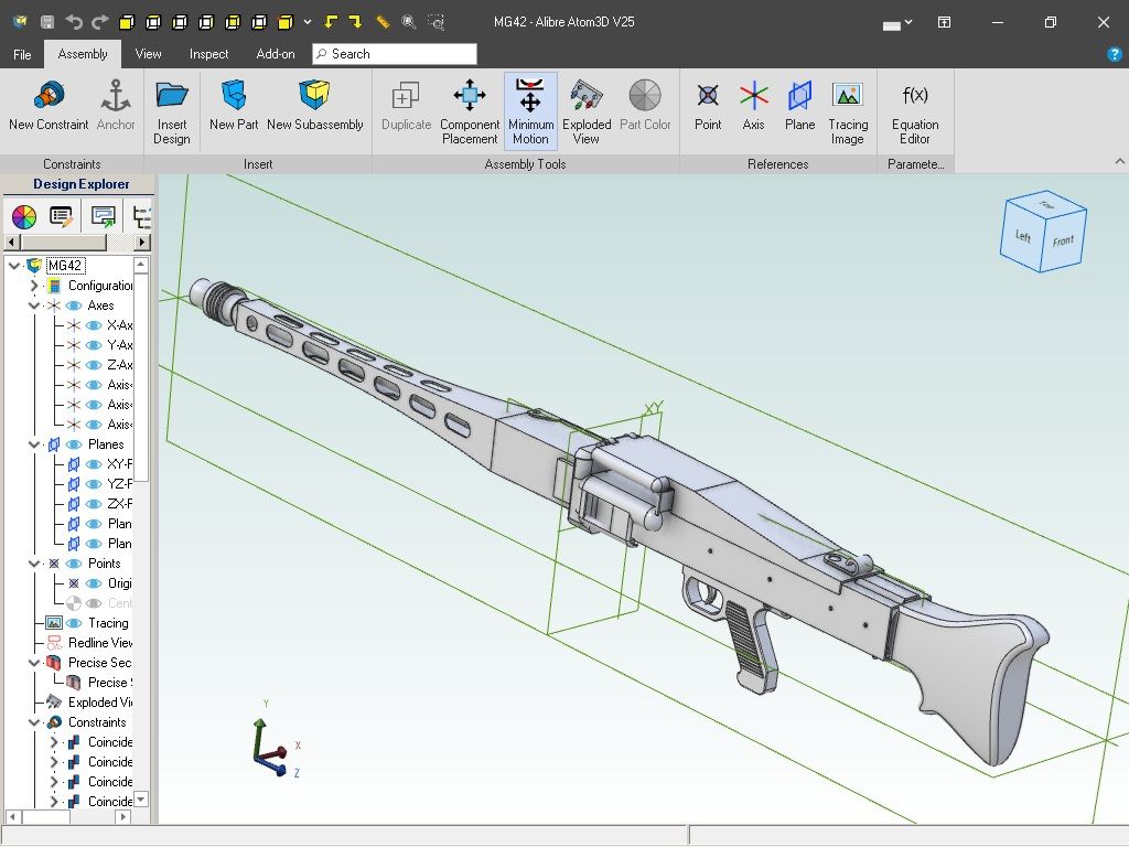
It took me a while to realise Alibre's Parts and Assemblies approach is not only of engineering significance. It eases that load problem by creating natural breaks. E.g., I'd not really appreciated that that MEW tutorial starts by modelling and saving what becomes a scribing-block base, not by modelling a scribing-block straight off.
So for a single-move exercise, for example, I could try that revolved-cut tool on a simple but fairly large-diameter cylinder, without worrying about what the cylinder might be for. It does help to be realistic though, such as the scribing-block parts on their own, other exercises like the boring-head or parts borrowed from some other plan-set, or by measuring actual metalwork.
(My realism point is from finding certain maths topics easier to learn if they have some real, physical "frame". I related 3D graphs [x, y, z] to the familiar Ordnance Survey maps' grid-references and contours.)
lee webster.


