Airbrush Compressors

Advert

Airbrush Compressors

Home Forums General Questions Airbrush Compressors

Viewing 12 posts - 1 through 12 (of 12 total)
  • Author
    Posts
  • #534423
    Turbine Guy
    Participant
      @turbineguy

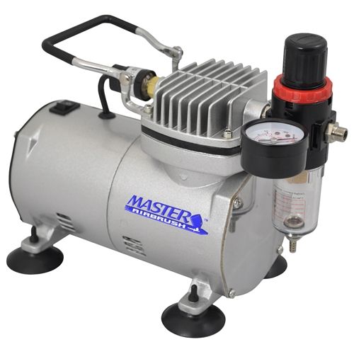
      I have a Master TC-20 airbrush compressor like shown in the picture below that I use for running my model turbines and steam engines When I started testing my model turbines and engines. I calculated the mass flow as described in Testing Models. Because all the flow was going through nozzles with published efficiencies and air acts like a perfect gas, I trusted these calculated mass flows. I have always assumed that the mass flow was constant for a positive displacement air compressor when using different pressures. I just noticed this compressor listed a flow of 0.8 cfm which I assumed to be at atmospheric pressure (scfm). This volume flow at standard conditions would be a mass flow of approximately 3.6 lb/hr. The mass flow I recently calculated for a 0.030” diameter nozzle throat and a pressure of 23 psig was approximately 1.8 lb/hr. I used a pressure gauge of 0-30 psig with a +/- 0.3 psi accuracy for this last calculation. After seeing this difference in mass flow, I made a nozzle with an 0.080” diameter throat and found that the pressure was approximately 2.0 psig to pass all the flow from my airbrush compressor with it running constantly. The mass flow for this pressure and nozzle throat diameter is estimated to be approximately 3.1 lb/hr which is fairly close to the mass flow shown for atmospheric pressure. This somewhat confirms my method of calculating the mass flow but shows that the mass flow is not constant for this compressor. The only three reasons I could think of for a drop in mass flow with an increase in pressure was leakage by the piston, change in speed, or external leakage. I ran the compressor with all my fittings and a plug in the hose where it would be clamped to the nozzle. I set the regulator to a pressure of 30 psig and then shut of the airbrush compressor. The pressure didn’t drop after waiting several minutes, so I assume no external leaks. I don’t know how much a AC motor like used to drive this compressor varies with load but would appreciate any input on this. I also don’t know what type of piston seal is used in this airbrush compressor but I assume even with a piston ring, there could be some leakage. I would appreciate any feedback about loss in mass flow with increase in pressure for this simple type of airbrush compressor.

      Master TC-20

      Edited By Turbine Guy on 17/03/2021 19:10:55

      Advert
      #28049
      Turbine Guy
      Participant
        @turbineguy
        #534430
        Dave Halford
        Participant
          @davehalford22513

          The 0.8cfm is the error, it assumes no losses.

          #534432
          Michael Gilligan
          Participant
            @michaelgilligan61133
            Posted by Turbine Guy on 17/03/2021 18:40:27:

            .

            I have a Master TC-20 airbrush compressor like shown in the picture below that I use for running my model turbines and steam engines […] I also don’t know what type of piston seal is used in this airbrush compressor but I assume even with a piston ring, there could be some leakage. […]

            .

            Judging by appearances … that compressor has a diaphragm, not a piston.

            To all practical purposes, there should be no leakage … unless the bolts are loose or the diaphragm is split.

            MichaelG.

            .

            The  principle is nicely illustrated here:

            https://www.researchgate.net/figure/Figure-B6-Schematic-of-diaphragm-compressor-operation-57_fig33_256761670

            Edited By Michael Gilligan on 17/03/2021 19:14:28

            #534447
            Turbine Guy
            Participant
              @turbineguy
              Posted by Michael Gilligan on 17/03/2021 19:11:10:

              Posted by Turbine Guy on 17/03/2021 18:40:27:

              .

              I have a Master TC-20 airbrush compressor like shown in the picture below that I use for running my model turbines and steam engines […] I also don’t know what type of piston seal is used in this airbrush compressor but I assume even with a piston ring, there could be some leakage. […]

              .

              Judging by appearances … that compressor has a diaphragm, not a piston.

              To all practical purposes, there should be no leakage … unless the bolts are loose or the diaphragm is split.

              MichaelG.

              .

              The principle is nicely illustrated here:

              **LINK**

              Edited By Michael Gilligan on 17/03/2021 19:14:28

              Hi Michael,

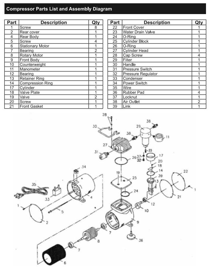
              I copied the following parts list shown in the Master TC-20 manual. It appears this airbrush compressor uses a single piston ring so leakage by the piston could occur and possibly slowing down of the motor with higher pressures. I am hoping someone can confirm that there is a drop in mass flow with increased pressure for this airbrush compressor.

              Thanks for your feedback,

              Byron

              TC-20 Parts List

              #534450
              Michael Gilligan
              Participant
                @michaelgilligan61133

                Evidently, appearances are deceptive

                Apologies for misleading you.

                MichaelG.

                #534455
                not done it yet
                Participant
                  @notdoneityet

                  That compressor will not be a positive displacement device on a gas. It cannot pump any higher than its effective compression ratio. You need an incompressible fluid for that – usually a liquid. Other means are used to positively displace a gas (where back-leakage would be the limiting the pressure achievable).

                  #534461
                  Dave Halford
                  Participant
                    @davehalford22513
                    Posted by Michael Gilligan on 17/03/2021 20:22:54:

                    Evidently, appearances are deceptive

                    Apologies for misleading you.

                    MichaelG.

                    Technically correct though Michael, the piston is called a link and the crank is a counterweight smiley

                    #534481
                    Michael Gilligan
                    Participant
                      @michaelgilligan61133

                      So, Byron … after my initial faux pas I had a look around

                      There is a YouTube video showing the internals of what looks like a very similar compressor

                      Search for: “AS 18 Air Brush Compressor Repair RC Model Geeks”

                      … it may be useful.

                      MichaelG.

                      #534676
                      Turbine Guy
                      Participant
                        @turbineguy

                        Hi Michael,

                        Thank you for showing the link. The video on This Link confirmed that this type of air brush compressor does use a piston seal described as being plastic and the parts looked like what was shown in my last post. I agree with what Dave pointed out, that the piston is called a link and no connecting rod is shown. If the piston and connecting rod are actually one part and the cylinder does not rock, the piston would need to tilt back and forth as it moves up and down.. There is only one very brief part of the video where the piston is pushed down slightly and it looked to me like the piston pivoted in the cylinder as it moved down. The piston seal would need to be very flexible and there would need to be enough clearance between the piston and cylinder to do this. This would put all the load on the piston seal and help to explain the large amount of seal particles that had to be wiped off.

                        Thanks for sharing this link,
                        Byron

                        #534680
                        Ex contributor
                        Participant
                          @mgnbuk

                          If you search for "Wobble piston compressor", several manufacturers come up, with descriptions of the operating principles, operating capabilities. etc.

                          Nigel B.

                          #534714
                          Turbine Guy
                          Participant
                            @turbineguy

                            Thanks Nigel,

                            This Wobble Piston Link illustrates the operation very well. You hit the nail on the head when you mentioned the Wobble Piston. This appears to be what is used in my airbrush compressor. I appreciate learning more about this concept. I think the link found by Michael that I showed in my last post answered my question about drop in mass flow with higher pressure. After restoring the airbrush compressor the man in the video ran two nozzles. The continuous running pressure for one was approximately 20 psig and for the other was approximately 30 psig. The two nozzle sizes for the set are 0.8mm and 0.3mm. The mass flow for these nozzle sizes and pressures are approximately 1.7 lb/hr and 0.24 lb/hr respectively using my assumed nozzle efficiency.

                            Thanks all of you for your help,

                            Byron

                          Viewing 12 posts - 1 through 12 (of 12 total)
                          • Please log in to reply to this topic. Registering is free and easy using the links on the menu at the top of this page.

                          Advert

                          Latest Replies

                          Home Forums General Questions Topics

                          Viewing 25 topics - 1 through 25 (of 25 total)
                          Viewing 25 topics - 1 through 25 (of 25 total)

                          View full reply list.

                          Advert

                          Newsletter Sign-up