Advice on Cluttered Dimensions in Drawings

Advert

Advice on Cluttered Dimensions in Drawings

Home Forums CAD – Technical drawing & design Advice on Cluttered Dimensions in Drawings

Viewing 24 posts - 26 through 49 (of 49 total)
  • Author
    Posts
  • #590944
    Baz
    Participant
      @baz89810

      If a drawing starts to get too cluttered with dimensions I do all X axis dimensions one layer and all Y axis dimensions on another, then I can print off two drawings for the workshop that are easier to read.

      Advert
      #590947
      JasonB
      Moderator
        @jasonb

        Dave as it's now clear it's for home use then no real need to worry about the latest BS standard or dimensioning styles just do it to suit the way you are going to machine it. It's only if you are going to make the drawing available to others you need to give it a bit more thought.

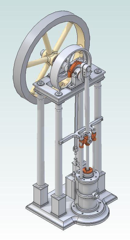
        Although I do a 3D model of all my engines and check holes line up and moving parts like cranks and conrods won't hit anything when turning I seldom print off drawings for use in the workshop to actually make the thing from. Typical 3D of the one I'm currently working on. I just take off what sizes I need from the 3D part and get on with making it

        unreal 3d.jpg

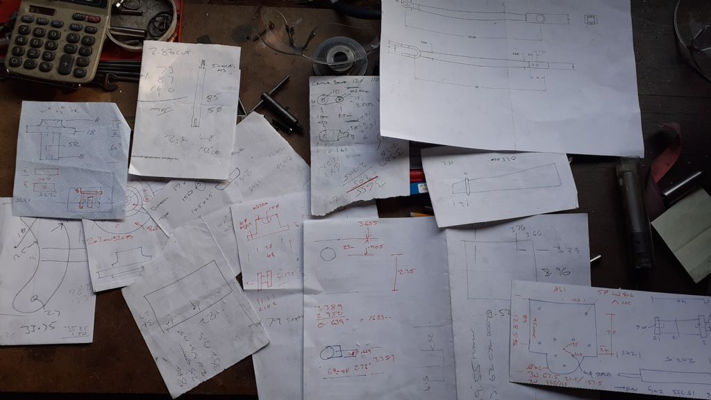
        I hope this won't make anyone choke on theirbeer but this is what it's built from, I think there is even an envelope or two in there and just one printed drawing.blush

        20220321_155413[1].jpg

        But it seems to work for me as yesterdays little video shows. If it's going in the mag or for work then I'll approach things a bit differently

        Edited By JasonB on 21/03/2022 16:22:26

        #590952
        SillyOldDuffer
        Moderator
          @sillyoldduffer
          Posted by Baz on 21/03/2022 16:03:08:

          If a drawing starts to get too cluttered with dimensions I do all X axis dimensions one layer and all Y axis dimensions on another, then I can print off two drawings for the workshop that are easier to read.

          That's a good idea and I can steal it for my go to 2D drawing package, QCAD.

          Unfortunately doesn't work for FreeCAD-Techdraw because it has no layers! (One reason why FreeCAD warn against using Techdraw for stand-alone 2D drawing: as it's meant for generating 2D drawings from 3D models it lacks many ordinary drawing features.)

          Dave

          #590956
          Nick Wheeler
          Participant
            @nickwheeler

            Jason's approach is mostly how I do things now. Creating the 3D model does most of the thinking required to make the part, and I find that a few dimensioned sketches are usually enough to actually do the job.

            Which means a drawing from the model only really needs to be clear to you. The examples above should be enough to allow you to do that.

            I wish programs like Fusion or Alibre allowed you to add visible dimensions to the live 3D views, as that would be even easier – no drawings with all the fudges required to represent 3D objects as elevations no longer needed at all.

            #590961
            Michael Gilligan
            Participant
              @michaelgilligan61133
              Posted by Circlip on 21/03/2022 08:49:29:

              […]

              Try using a common datum when trying to locate a cylinder with eight mounting holes and forget all your fancy measuring systems. One hole is datum and the rest are chained from it. […]

              .

              It’s personal preference, of course, but: Based on my preferred way of machining [with either a rotary table on the BCA, or with a drilling head on the lathe] I would much prefer see the centre of the cylinder as a datum and the mounting hole centres dimensioned by polar co-ordinates.

              Each to his own angel

              MichaelG.

              #590973
              SillyOldDuffer
              Moderator
                @sillyoldduffer
                Posted by Nicholas Wheeler 1 on 21/03/2022 17:02:30:

                Jason's approach is mostly how I do things now. Creating the 3D model does most of the thinking required to make the part, and I find that a few dimensioned sketches are usually enough to actually do the job.

                Which means a drawing from the model only really needs to be clear to you. …

                Me too: perhaps the biggest advantage of 3D modelling is the way it power-assists the thinking process. I also end up working from a pile of paper notes and sub-standard drawings derived from the 3D model. Jason's photo could have been taken in my workshop:

                But the approach is only suitable for singleton workers. I think it's still necessary to produce good 2D technical drawings whenever a design has to be built by others manually. The 3D-CAD to notes technique works well for me, but I doubt the readers of Model Engineer Magazine would be happy with that approach.

                There are worse sins than clutter. Missing and incorrect dimensions and datums; dimensions that look right on individual drawings, but parts made from them won't fit together; mixed units; too thin lines; weird abbreviations and symbols; irrelevant or too few dimensions; and fractions!

                Dave

                #590995
                Andy Stopford
                Participant
                  @andystopford50521

                  Ordinate dimensions can help with 'de-cluttering', and work well with a DRO-equipped mill.

                  Take care though, that you don't do what I did last weekend and read the last hole position as the length dimension of your workpiece. Its exceedingly annoying to find that the last of the numerous holes that you've so carefully, so precisely, drilled lies on that misplaced edge…

                  #590998
                  paul rayner
                  Participant
                    @paulrayner36054
                    Posted by JasonB on 21/03/2022 16:20:55:

                    Dave as it's now clear it's for home use then no real need to worry about the latest BS standard or dimensioning styles just do it to suit the way you are going to machine it. It's only if you are going to make the drawing available to others you need to give it a bit more thought.

                    Although I do a 3D model of all my engines and check holes line up and moving parts like cranks and conrods won't hit anything when turning I seldom print off drawings for use in the workshop to actually make the thing from. Typical 3D of the one I'm currently working on. I just take off what sizes I need from the 3D part and get on with making it

                    unreal 3d.jpg

                    I hope this won't make anyone choke on theirbeer but this is what it's built from, I think there is even an envelope or two in there and just one printed drawing.blush

                    20220321_155413[1].jpg

                    But it seems to work for me as yesterdays little video shows. If it's going in the mag or for work then I'll approach things a bit differently

                    Edited By JasonB on 21/03/2022 16:22:26

                    Would be nice to see this in the mag

                    #591029
                    JasonB
                    Moderator
                      @jasonb

                      It will either be on the forum or possibly in the mag. If in the mag I better tidy up that pile of drawings but that is the sort of thing that sometimes gets sent in so I think the designer does quite well producing the drawings from that sort of material.

                      #591053
                      Circlip
                      Participant
                        @circlip

                        And hopefully, the graphic artist that tarts them up for the Mag. will get all the dimensions correct.

                        Regards Ian.

                        #591055
                        SillyOldDuffer
                        Moderator
                          @sillyoldduffer
                          Posted by JasonB on 22/03/2022 07:15:48:

                          It will either be on the forum or possibly in the mag. If in the mag I better tidy up that pile of drawings but that is the sort of thing that sometimes gets sent in …

                          Looking forward to seeing the engine in print – it's another cracker.

                          I've not noticed any quality issues in Jason Ballamy publications, so how is the 'tidy up' done? Do you work from the 2D drawings produced by the 3D-CAD tool, redraw them from the working Notes, or what?

                          My interest in technical drawing is partly because I enjoy doing them well, and partly because I want anything I share with others to be clear. I often fail, so very much a work in progress!

                          I feel for the magazine editors if they have to make proper drawings from the sort of rough jottings I use in the workshop! No wonder mistakes creep in.

                          I've fixed my USB/3D-Printer problem, so might be able to play with dimensions. Except I ought to load the car with junk and visit the tip…

                          Dave

                          #591105
                          JasonB
                          Moderator
                            @jasonb

                            Dave, it's a number of things.

                            As I build I may make small changes and try to update the 3D model as I do, so checking that is up to date is one thing.

                            I may well have drawn parts that I have machined on the CNC but as most don't have one I may tweak a few features to make it easier for those with manual machines. or draw up alternatives.

                            Then I'll start drawing, if going into the mag then A4 suits as Martin can shrink it down to A5 and get two drawings to a page so designer does not get involved. So I have to bear this in mind and mot make parts too small that they are hard to see at the reduced size though not a problem for digital subscribers. Those actually making one of my designs in ME usually end up with the A4 drawings anyway.

                            I'm also aware that putting one sheet on a page will not make subscribers happy as it will bulk out the length of the article so will try and group smaller related parts together on one sheet but try not to overcrowd it.

                            People also seem to like a BOM so I'll pull one of those off the assembly and use that as a basis for a table.

                            Not sure where this one will end up as on the one hand it could see sales of Stuart cylinders and flywheels increase but on the other it may see sales of the Real kit decrease so it may be better kept to the forum(s) where I can freely post my thoughts on castings for casting sake etc.devil

                            #591141
                            SillyOldDuffer
                            Moderator
                              @sillyoldduffer
                              Posted by JasonB on 22/03/2022 13:24:52:

                              Dave, it's a number of things.

                              Thanks Jason, good hints. I like a BOM.

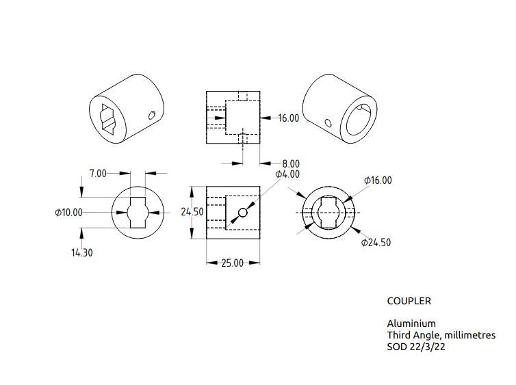
                              This is the fruit of this afternoon's interrupted labours, no peace for the wicked:

                              cleancoupler.jpg

                              Happier with this, done by spreading the dimensions across views. Need to try a more complex example though – the coupler is pretty simple. Delighted to get more suggestions.

                              Dave

                              #591159
                              duncan webster 1
                              Participant
                                @duncanwebster1

                                Rather than writing 'third angle', where you have to remember what it means, the industry norm is to have the elevation and end view of a bucket, normally place centre bottom of sheet where I worked

                                #591163
                                Jon Lawes
                                Participant
                                  @jonlawes51698

                                  We rely on the goodwill of hard working people who effectively volunteer their time to create drawings for our hobby (I know the magazines pay, but lets face it most are doing it for the benefit of their hobby rather than to line their pockets). The drawings are not going to be perfect all of the time, but there are people still producing them despite a wave of hostility from onlookers. We should be grateful rather than trying to tear them to pieces. This is a hobby largely full of enthusiastic amateurs.

                                  One of my most vocal critics at the model engineering society I attend has frequent, loud advice for me, usually prefaced with "you know what you are doing wrong…" or "you know your problem don't you…". This is from someone who once let slip he last used a lathe at school, 45 years ago, and has driven a locomotive once. But the advice keeps coming.

                                  Nice, polite advice is always welcomed, especially from those who maybe had careers in whatever the subject at hand is. But sometimes the holier than thou snobbery on this forum is nothing short of discouraging. Calling out others opinions as rubbish, belittling others, all this crap, it really needs to stop. It's just elitist attitudes that will kill our hobby dead.

                                  #591178
                                  Grindstone Cowboy
                                  Participant
                                    @grindstonecowboy

                                    Well said Jon

                                    Rob

                                    #591194
                                    Nick Wheeler
                                    Participant
                                      @nickwheeler

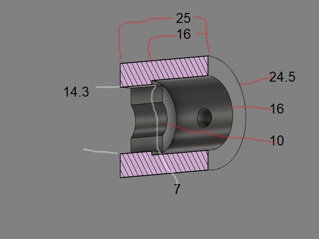
                                      I'd quite happily head to the workshop with something like this

                                      coupler.jpg

                                      if it didn't take exporting a CAD image into another program and annotating manually. Doing that simple part was tedious, it isn't practical for a complicated one.

                                      If I draw on paper, it looks like a child's attempt to copy Picasso's version of the Mona Lisa. Or a water damaged print of the Eiffel Tower.

                                      #591214
                                      JasonB
                                      Moderator
                                        @jasonb

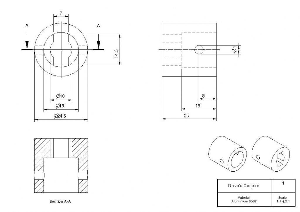
                                        Dave, looking at your drawing there are a few points

                                        I still think it looks a bit cluttered, if the isometric views were separated from the actual 2D working drawings you could lay it out better, maybe make the iso ones smaller.

                                        The 4.00dia as close to the 8.00mm dimension and also the opposite end of the 16dia arrow

                                        The 4mm hole does not have a dimension from the end of the workpiece.

                                        This has lost a bit of clarity being snipped but clearer if clicked on. I think just the two elevations can hold all the dimensions needed buy have added a section for good measure. Isometric have been made smaller and away from the 2D. Dimension lines on the two elevations have been lined up with each other which looks neater. All on an A4 sheet

                                        daves draw.jpg

                                        Edited By JasonB on 23/03/2022 08:22:15

                                        #591224
                                        Circlip
                                        Participant
                                          @circlip

                                          Sorry if your sensitivities have been offended Jon but when 'Theoretical' P/C rears its ugly head, as a PRACTICAL ingineer of over fifty years (now long retired) in the manufacture (yes, got me hands mucky and cut as an apprentice), design and specification of components and items for the mechanical, electrical and electronic industries, I think I can validate my reply. With all due respect, last time I read BS (aptly acronymed) 308 was when a copy was stuffed under my nose after being 'promoted' into the D/O. Last time I used it practically was as a packing shim under a wobbly table. For those who glibly quote DROs and rotary tables, haven't seen many companies with 32ft long versions for one or two off requirements. But we are making toys and trying to apply 'Theoretical industrial standards' interrupts getting the show on the road. If your drawings are to be used for mass production, they are to a different standard than Joe Soap making a one off, NOT to say that the interactive dimensions shouldn't work but when some start bleating "What about tolerances", we're making one off toys for our own amusement, not 10,000.

                                          Going back to the O/Ps original problem, two solutions, move the component to the left a bit on the drawing or use a bigger bit of paper. Even with the 'Constraints' of slavishly following BS308, with a pencil and rule you still have the ability to 'do your own thing' but with Acad and ALL its clones, unless you can find all the hidden tweaks, you're limited to drawing lines but the program(me) determines annotation styles.

                                          Regards Ian.

                                          And for the blue pencil brigade, You might not like what I say, but that doesn't mean I'm wrong.

                                          Edited By Circlip on 23/03/2022 10:20:24

                                          #591229
                                          Nick Wheeler
                                          Participant
                                            @nickwheeler

                                            Ian's post above sums it up for me, as I'm only ever going to be making stuff for me. So it simply isn't worth the time to learn how to make any drawings match a standard other than the one that makes sense to me.

                                            So while Jason's latest revision is clear, I would still change it to suit the way I would make the part:

                                            the diameters would be moved to the top right, along with the lengths, as they're all done as part of the same setup.

                                            I would move all of the dimensions for the 4mm cross-hole to the the section, because it's another setup.

                                            And the top left would only have the dimension for the slot – width, height and hole diameter.

                                            All of that would immediately make sense to me when I come to make the part 18months after designing it…

                                            After all, the drawing is only a step on the way to having the actual part working.

                                            As for tolerances, I would suggest that the only bits that matter are the slot and the cross-hole; everything else is either there to place the holes, or for clearance around the coupled parts so appropriate methods apply – like starting the 16mm bore with a 5/8" drill then finishing and flattening the bottom with a 16mm endmill, or cleaning up the outside diameter of 1" bar with some emery tape.

                                            #591244
                                            JasonB
                                            Moderator
                                              @jasonb

                                              Yes we can all do it as suits our needs as per my rouch sketches.

                                              Regarding The post above I personally try to avoid dimensioning hidden detail and if you look at some of my drawings in the mag I may well have called out "16dia x 16deep" .Or dimentioned the section and not had the side elevation.

                                              Also if grouping for setup then I would have the 10mm hole with the other concentric diameters and have drilled right through 10mm then opened up the 16mm. all while in the lathe.

                                              Regarding mass production, do they still use 2D drawings or just send a file electronically ? and even if you do send off a DWG or DXF it only needs the one dimension as a check so you don't get apart 10ft long that should have been 10mm. I've even sent people a single .STP file of an assembled engine and they have made one from just that, all the info is there for them to make it the best way that suits them.

                                              #591247
                                              Circlip
                                              Participant
                                                @circlip

                                                Regarding mass production, do they still use 2D drawings or just send a file electronically ?

                                                Don't know, and now care even less. The ability to send drawings add lib at the speed of light by one national customer that had different dimensions at different times WITHOUT changing the drawing issue have long gone.

                                                Regards Ian.

                                                #591313
                                                Jon Lawes
                                                Participant
                                                  @jonlawes51698
                                                  Posted by Circlip on 23/03/2022 10:03:25:

                                                  Sorry if your sensitivities have been offended Jon but when 'Theoretical' P/C rears its ugly head, as a PRACTICAL ingineer of over fifty years (now long retired) in the manufacture (yes, got me hands mucky and cut as an apprentice), design and specification of components and items for the mechanical, electrical and electronic industries, I think I can validate my reply.

                                                  My point is still valid. The content of your reply might be but it rather gets lost in the noise.

                                                  #591406
                                                  SillyOldDuffer
                                                  Moderator
                                                    @sillyoldduffer

                                                    Special Mention in Despatches for Nicholas. His version gets the prize for maximum information in the smallest spacer without clutter:

                                                    Unfortunately, it's a little unexpected, and as Nicholas says: 'Doing that simple part was tedious, it isn't practical for a complicated one.' One oddity, when I first looked at it I saw an Einstein's Head inversion! Despite the brief optical illusion I like it. I believe FreeCAD/TechDraw could create most of the drawing automatically, so it may be more practical than Nick believes. I'll try it later.

                                                    First prize goes to Jason.

                                                    It's cleaner than my attempt and I'm sure TechDraw can do the same. Watch this space.

                                                    Been reading what my 1947 Newnes Engineer's Reference Book has to say about Drawing Office Practice. It's based on B.S.S 308(1943) and how it differs from B.S.S 308(1927). Nothing is ever simple – two BS308s.

                                                    Much good advice in Newnes, but BS308 can be verbose too, as in 'Hole letter G drill (0.261" dia)'. And hard to see how clutter is avoided if BS302 surface finish, tolerance and other production information is added. Fortunately not needed on most home workshop drawings.

                                                    Newnes casts an interesting light on who actually produced the old Technical Drawings I admire so much. Good chance it wasn't a Draughtsman!

                                                    Newnes advises draughtsmen to concentrate on design, leaving most of the actual finish drawing to Tracers. Tracers specialised in producing the clean fully populated drawings needed for production from the Draughtman's drawings and notes. The tracer decided how the drawing looked and how it was completed: line thicknesses, dimension placements, titles, version numbers, reference numbers, colour, hatching, sections, and tables etc. He drew the nice arrow heads and other posh features.

                                                    Another specialist, the Checker, reviewed drawings independently before they were submitting them to the Chief Draughtsman/Drawing Office Manager for final approval. Big Drawing Offices were a team effort, with many opportunities to spot mistakes before anything got to a machinist. As I have to combine all these roles, and am untrained in all of them, I don't feel so bad about my mistakes now!

                                                    Dave

                                                  Viewing 24 posts - 26 through 49 (of 49 total)
                                                  • Please log in to reply to this topic. Registering is free and easy using the links on the menu at the top of this page.

                                                  Advert

                                                  Latest Replies

                                                  Viewing 25 topics - 1 through 25 (of 25 total)
                                                  Viewing 25 topics - 1 through 25 (of 25 total)

                                                  View full reply list.

                                                  Advert

                                                  Newsletter Sign-up