Adjusting the horizontal mill

Advert

Adjusting the horizontal mill

Home Forums Beginners questions Adjusting the horizontal mill

Viewing 25 posts - 26 through 50 (of 55 total)
  • Author
    Posts
  • #578222
    AJAX
    Participant
      @ajax
      Posted by Steve355 on 03/01/2022 11:25:51:

      Posted by Dave S on 03/01/2022 10:49:20:

      How is the feed taken off?

      Could you change the spindle pulley and a subsequent feed pulley to give a more appropriate ratio?

      Dave

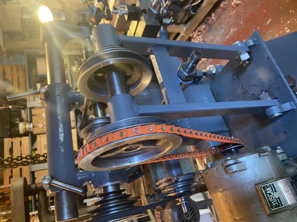
      I don’t think so, the feed pulley for the spindle is about as small as it can be and the spindle pulley is about as big as it can reasonably be. See pic below.

      I feel a vfd coming on, wallet is getting worried.

      b89dee39-b1b2-4d48-8811-436de779fb9c.jpeg

      I'm rather late to this thread, and this may have already been discussed, but that intermediate stepped pulley on the countershaft looks like it may be too big. If be tempted to try a smaller pulley if you have one.

      Otherwise, as you already realise, a VFD may be a good option. I chose a VFD and 8 pole 3 phase motor for my horizontal mill as these motors have plenty of torque at low speeds (680 rpm at 50hz).

      Advert
      #578223
      AJAX
      Participant
        @ajax

        As an aside, I just noticed you are running a Tuscan flame proof motor. I saw one of these for sale cheaply not long ago but was put off by thoughts of sealing/heating, although maybe they are not so different from TEFC motors. Do you find it works well for you?

        #578228
        Steve355
        Participant
          @steve355
          Posted by AJAX on 03/01/2022 12:08:58:

          As an aside, I just noticed you are running a Tuscan flame proof motor. I saw one of these for sale cheaply not long ago but was put off by thoughts of sealing/heating, although maybe they are not so different from TEFC motors. Do you find it works well for you?

          TBH I don’t really know, I haven’t got the mill running properly. It is quiet and seems smooth. It is unbelievably heavy. It has a warning on it that says don’t run it for longer than an hour, so for a home milling application I guess it is fine.

          Any thoughts on the 3 phase/VFD? What model did you get? I will be budget limited. But it does make sense as the original motor was geared with a much lower rpm. That's how the mill was designed to run – in fact with the geared motor belted directly to the shaft.

          Steve

          #578232
          JasonB
          Moderator
            @jasonb

            What are the three speeds you get at the spindle? It looks as though you have a countershaft that will do the same job as the gearhead motors of the originals so the VFD should not be needed

            You want the countershaft to be turning at about 250-280 rpm. This looks quite possible eyeballing the motor pully against the much larger countershaft one.

            From that you have 3 pully ratios which should give something like 80, 250, 750 at the spindle. The 3 step countershaft pulley looks a bit big so may not give these speeds but should be cheap enough to change

            You then have a 4 step pully which should give 4 rates of feed, work these out as a ratio eg 4:1, 3:1,2:1 and 1:1

            Finally work out what one turn of the input to the feed shaft gives in the way of table movement, it is unlikely to be direct unless the bevel gears are the same tooth count. You can then use that to work out the 4 feed rates per revoultion of the spindle.

            Feeds are best expressed as distance per revolution of the spindle not in inches as the distance will change as spindle speed changes even if the feed per rev is constant.

            Edited By JasonB on 03/01/2022 13:28:55

            #578235
            Steve355
            Participant
              @steve355
              Posted by JasonB on 03/01/2022 13:26:08:

              What are the three speeds you get at the spindle? It looks as though you have a countershaft that will do the same job as the gearhead motors of the originals so the VFD should not be needed

              You want the countershaft to be turning at about 250-280 rpm. This looks quite possible eyeballing the motor pully against the much larger countershaft one.

              From that you have 3 pully ratios which should give something like 80, 250, 750 at the spindle. The 3 step countershaft pulley looks a bit big so may not give these speeds but should be cheap enough to change

              You then have a 4 step pully which should give 4 rates of feed, work these out as a ratio eg 4:1, 3:1,2:1 and 1:1

              Finally work out what one turn of the input to the feed shaft gives in the way of table movement, it is unlikely to be direct unless the bevel gears are the same tooth count. You can then use that to work out the 4 feed rates per revoultion of the spindle.

              Feeds are best expressed as distance per revolution of the spindle not in inches as the distance will change as spindle speed changes even if the feed per rev is constant.

              Edited By JasonB on 03/01/2022 13:28:55

              hi Jason

              The motor rpm is 1480

              The countershaft is 525

              At the spindle I get 250, 500 or 850 depending on the pulley used.

              That all seems to make sense, the motor is just too fast.

              I haven’t mapped all the different (12) feed rates yet. When I get a chance I will do that. But I will give it a go later, based on distance per revolution as you say. I can do that with a dial indicator.

              #578236
              Anonymous

                I'm puzzled as to why the feedrate varies with spindle speed, it's not logical. My mill has a separate 1hp feed motor and gearbox, but on a mill with a single motor for both functions I would expect the feed drive to come directly off the motor shaft, not the arbor. Sounds like a fudge by a previous owner.

                I'd be wary about using a VFD. Of course it is useful in order to run a 3-phase motor, but in this application I'm not convinced that the variable speed ability is useful. As the motor speed varies so will the feedrate, and as the motor speed is reduced below base speed (normally at 50Hz) the available power will also decrease. in proportion.

                Andrew

                #578243
                Steve355
                Participant
                  @steve355
                  Posted by Andrew Johnston on 03/01/2022 13:42:14:

                  I'm puzzled as to why the feedrate varies with spindle speed, it's not logical. My mill has a separate 1hp feed motor and gearbox, but on a mill with a single motor for both functions I would expect the feed drive to come directly off the motor shaft, not the arbor. Sounds like a fudge by a previous owner.

                  Andrew

                  Doesn’t make a great deal of sense to me either but it’s the original setup. See below drawing. Also I found a list of original motor options … which I don’t fully understand.

                  2c8fd677-8b56-4a47-b8ee-79ff7ca2d391.jpeg

                  70383bb6-9290-4eb1-ab0d-27969ee1fd06.jpeg

                  #578244
                  Clive Foster
                  Participant
                    @clivefoster55965

                    Thats a reasonably spacious drive system.

                    If you go for poly-vee drive there is ample room to add an intermediate countershaft and make it a two stage reduction drive. With two stages you'd not have to have everything in a straight line which further eases the pully size issue. Perhaps 25 mm to 70 mm and 35 mm to 100 mm for the two stages getting close to the 5.61 reduction you have calculated. Eyeball engineering says larger drive pulley on the second stage as there will be more torque involved but realistically poly-vee belts can handle much more power than I think they ought.

                    3 rib PJ belts are similar price to A section Vee and, with only three ribs, easy to make pulleys for.

                    Last time I did a similar job I used the main bearings and support castings salvaged from a dead spin drier. Two U bolt exhaust pipe clamps later we were in business.

                    Potentially easier way, if there is nothing suitable for a countershaft in the useful bits box, id to fix the two countershaft pulleys together add bearing(s) and spin on a stationary shaft. Cheap ball races or oilite bushes have both worked for me.

                    Effective though VFD systems are I always think you are best off getting the basic drive ratios right to mainatin lower speed torque then add in the VFD to maximise flexibility.

                    Clive

                    Edited By Clive Foster on 03/01/2022 14:17:31

                    #578246
                    Steve355
                    Participant
                      @steve355

                      Actually Clive, I may have a better (?!) idea. Another idea anyway. 😎

                      it turns out the motor drive shaft fits myford change wheels, quite a few of which I have lying about. It shouldn’t be too hard to make a little 2:1 reduction gearbox that sits over the motor spindle. Just need an arbor, a couple of bronze bearings and some sheet steel.

                      Thoughts?

                      #578259
                      JasonB
                      Moderator
                        @jasonb

                        "I'm puzzled as to why the feedrate varies with spindle speed, it's not logical."


                        The feed rate does not vary with spindle speed if you work it out as distance/rev as I said earlier.

                        But if measured in inches than 3" /min at 250 will be 6" /mion when the spindle is running at 500rpm

                        The 4 step pully from spindle to feed drive is no different to a set of lathe change gears or a gearbox with feed rated, carriage will move faster as revs go up but distance /rev stays the same.

                        That countershaft speed seems very high based on the small motor pully and large pully on the end of the countershaft, What are their diameters

                        Edited By JasonB on 03/01/2022 15:32:07

                        #578323
                        Clive Foster
                        Participant
                          @clivefoster55965

                          Concerning the practicality of making a gearbox using Myford gears first thoughts are that you are likely to need earplugs.

                          Need to be very accurate to make a quiet running gearbox and to use good quality gears. Changewheels in general aren't wonderfully well made as they mostly don't run particularly fast or transmit significant power. I found it instructive to compare the beautifully made and finished gears inside my P&W model B headstock with the rather rougher specimens in the external drop gear train. Nice enough but lon the lower side of ordianry and certainly the main noise source.

                          More to making a gearbox than it might seem at first sight too. All the makings of a classic "Why did I think it was a good idea to start this job?" project as things you didn't really think through come crawling out of the undergrowth around half way. (I'm slogging through one of those right now. Drawings much more incomplete than they looked.).

                          Pulley and belt systems generally give you much more flexibility to just make things fit.

                          3 rib PJ pulleys can be gotten out of 15 mm alloy plate. Cut close to side and mount on a short stub with loctite and a couple of Dutch keys (screws centred on the dividing line in holes tapped half in each component) to finally size and do the ribs. For pulleys mounted on a shaft the stub can be left in situ and bored to fit the shaft before parting off with a suitable overhang for the grip screws. Do the grip screw tapped holes first before fitting the pulley blank. If putting a pair on bearings best to make the stub double length and fit both blanks before finish turning. Bore the stub to take the bearings, part off and face neatly to finish off.

                          Always seems easy to me but I've done it a time or three, so I would say that wouldn't I.

                          Clive

                          #578338
                          Anonymous
                            Posted by JasonB on 03/01/2022 15:31:30:

                            The feed rate does not vary with spindle speed if you work it out as distance/rev……….

                            It's not particularly useful to describe the feedrate on a lathe in terms of distance per unit time. Conversely it's not particularly useful to describe the feedrate on a mill in terms of distance per revolution.

                            I expect that the mill was originally designed for use with an overhead flat belt driving the spindle. Creating the feeds from the spindle would be simple if not ideal. Looking at the diagram above there should be four feeds which will vary in proportion with each of the main spindle speeds.

                            Andrew

                            #578341
                            JasonB
                            Moderator
                              @jasonb

                              Agree it's not useful but it is the way these mills seem to have been made with feed drive being taken off the spindle

                              Still easy enough to work out. If at 250rpm the feed is 3"/min then 3/250 = 0.012" per rev so taking your 12T cutter as an example that will be feeding at a chip load of 0.001" per tooth, If the OP can give us the other feed distances it won't be hard to work out the rest.

                              #581912
                              Steve355
                              Participant
                                @steve355

                                Back to this project again after a few weeks away from it….

                                Basically the motor that came with this mill is too fast at 1480 rpm. The original motor that would have been supplied was geared and would have had a much lower rpm (capable of running the mill at 66-2850 rpm). The lowest I can get is 250. I need half that to get into the right territory.

                                I could add an extra countershaft and pulley, but the bits wouldn’t necessarily be cheap and it would be another project in the way of the mill working properly.

                                More expensive but easier and more flexible is a motor/VFD package. There’s a chap on eBay selling a VFD, motor, controller box and wiring as a package. Not cheap but it would move me forwards.

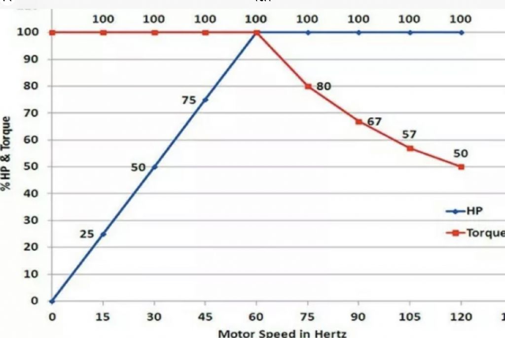
                                The thing is I don’t understand the hp rating of these setups at low rpm. They have linearly lower hp, but high torque – see diagram. My question is, does this matter? Or is it torque I need rather than hp?

                                I have seen lots of geared motors for sale but they all have very low hp. Again, does this matter? Or are they high torque?

                                thanks

                                Steve

                                d0bfc857-d34c-46e9-ad34-36595fe1a09f.jpeg

                                #581915
                                Anonymous

                                  The graph shows what one would expect for a motor driven by a VFD with base speed at 60Hz. Below 60Hz the torque is constant, and power decreases linearly, Above base speed power is constant, and torque decreases in proportion to the increase in speed.

                                  Metal removal rate is determined by available power, not by torque. Looking at the graph if the motor is running at 30Hz then power is down by 50% and you will only be able to remove 50% of the metal per unit time. A belt, or geared, drive system is constant power, which is what you need. As the speed decreases the torque increases to keep power constant.

                                  Reducing speed by using a VFD, without changing the belts, is simply going to cripple the mill in terms of metal removal rates.

                                  Andrew

                                  #581917
                                  Steve355
                                  Participant
                                    @steve355

                                    Thanks Andrew, that’s what I needed to know.

                                    I wonder why they are so popular then, I’ve seen lots of YouTube videos of people seemingly happily using VFDs with lathes et cetera.

                                    never mind, I’ll have to work on the pulley system.

                                    Thanks

                                    Steve

                                    #581928
                                    SillyOldDuffer
                                    Moderator
                                      @sillyoldduffer

                                      Posted by Steve355 on 23/01/2022 13:15:45:

                                      More expensive but easier and more flexible is a motor/VFD package. …

                                      The thing is I don’t understand the hp rating of these setups at low rpm. They have linearly lower hp, but high torque – see diagram. My question is, does this matter? Or is it torque I need rather than hp?

                                      I have seen lots of geared motors for sale but they all have very low hp. Again, does this matter? Or are they high torque?

                                      thanks

                                      Steve

                                      d0bfc857-d34c-46e9-ad34-36595fe1a09f.jpeg

                                      First, you might try fitting a 6-pole 750rpm motor. This example from Bearing Boys is 0.75kW, other powers available.

                                      Second, control it with a VFD. The 6-pole/750rpm motor is better placed to deliver lower RPM whilst maintaining power output than a 1500rpm motor.

                                      Torque and Power make my head hurt, but I'll have a go at explaining it/

                                      • Power is the rate at which work can be done, note time and a unit of work are both involved. An example might help to put the two in perspective. 1HP (746W) allows approximately 1 cubic inch of steel to be removed in one minute. Therefore a ½HP motor will take twice as long (2 minutes) to remove a cubic inch of steel, and a 2HP motor will remove one in 30 seconds. As about 1 cubic inch per minute is a rate of work that suits most ordinary workshops, 'our' machines typically come with motors in the ¼HP to 2HP range. I guess Model Engineering tools average about 1HP, which is always a good guestimate – not too weedy and not over the top bonkers.
                                      • Torque is twisting force, measured in Newton Metres. Imagine a stopped motor at the moment it's switched on. As RPM is zero, the motor cannot be doing any work – it's power output is also zero. Torque is the force that accelerates the motor up to speed. When the motor is delivering power, applying a braking force greater than the Torque will stall the motor.

                                      The amount of Torque produced depends much on the design of the motor. Single-phase motors and petrol engines both suffer low torque at low RPM, and need to be up to speed before the load is applied. Three-phase motors have much higher starting torque, and stepper motors deliver maximum torque when stopped. All motors lose torque when over sped.

                                      Even though it's vital I tend not to worry about torque much. Machine tools aren't heavily loaded from the get go. Therefore, provided the motor is of reasonable power, it should have enough torque to start and accelerate up to operating speed. If the operator stalls a machine running at design speed, he's working it too hard. Bad driver: back off. Unfortunately, overheating, mangled brushes, sheared gears and other damage are likely before a stall finally issues a Red Card.

                                      The graph means the motor delivers best power and torque at 60Hz. No surprise in a motor designed to run at US mains frequency. The motor maintains Torque as the VFD frequency and hence RPM drop – it won't stall. But the rate at which the motor can do work does fall with frequency. It's power output is halved at 30Hz, so it would take twice as long to finish the same work done at 60Hz. The graph also shows that speeding the motor up maintains the power output (it doesn't increase), but the torque falls. It's twice as easy to stall the motor at 120Hz than at 60Hz. (A VFD is likely to reduce this effect electronically.)

                                      Loss of torque and power might make the VFD sound a dicey proposition, but speed control is a major advantage that usually outweighs the disadvantages. For example, surface speed is arguably more important when cutting metal than power or torque. Certainly true of my lathe which I measured with a Wattmeter: even though the motor is good for 1.5kW out, I never use anything like that during normal work. Usually power input is between 200W and 1000W, with most cuts taking about 800W. The VFD, helped by a simple two speed belt runs the spindle at the RPM I want without any practical effect on power or torque.

                                      When speed is changed with a gearbox or belt drive the ratio effects speed and torque inversely. The relationship is simple: decreasing speed increases torque, whilst increasing speed decreases torque, both pro-rata.

                                      Dave

                                      #581938
                                      Anonymous
                                        Posted by Steve355 on 23/01/2022 14:04:27:

                                        ….people seemingly happily using VFDs with lathes….

                                        VFDs are a convenient way of using an existing 3-phase motor, and make changing speed simple. They also have other useful features such as soft start and current limiting. But consider the following:

                                        1. Some people don't understand how VFDs work, and the tradeoffs involved

                                        2. Some modellers don't run their machines to the limit, so a VFD is often fine

                                        3. Some people don't know the following equation: Power (W) = torque (Nm) x angular velocity (rad/sec)

                                        Andrew

                                        #581942
                                        Anonymous

                                          Posted by SillyOldDuffer on 23/01/2022 15:00:09:

                                          …stalls a machine running at design speed, he's working it too hard. Bad driver..

                                          embarrassed

                                          At least my machines are ex-industrial so they don't issue red cards when you stall them.

                                          Andrew

                                          #582019
                                          Steve355
                                          Participant
                                            @steve355

                                            Ok, finding one that is rated for full power at 750rpm makes sense.

                                            I found this one that says it runs at up to 1400 rpm, albeit with less torque.

                                            **LINK**

                                            Would this be a suitable VFD?

                                            **LINK**

                                            Steve

                                            #582085
                                            Anonymous

                                              The data implies the motor will only run at 1400rpm (100Hz) intermittently, ie, not continuously. I can't see anywhere the duty cycle for intermittent operation. It will only run continuously at 1000rpm (70Hz). Otherwise it seems fairly standard and does what one would expect below 50Hz. The only caveat being that at very low speeds the power output is negligible.

                                              The VFD is basic but seems to be fine. The easy guide gives clear diagrams for fitting external speed and direction control switches. In standard form it is not possible to fit a potentiometer for controlling the speed. One would need to buy the optional I/O expander.

                                              Andrew

                                              #641174
                                              Steve355
                                              Participant
                                                @steve355

                                                Back to this project after more than a year! Project status: Burke #4 horizontal mill works, however, when using slitting saws to cut steel etc, the minimum 250 RPM is way too high, resulting in burnt chips, lots of heat, worn out cutters etc. my understanding is that it needs to be more around 70 RPM to get good results.

                                                I really want to use the mill for other projects now and don’t really want to embark on another engineering project – so the simplest and quickest, not necessarily the cheapest solution fits the bill.

                                                current rpms:

                                                Motor Countershaft S1 S2 S3
                                                1540 525 250 512 683

                                                Options

                                                option 1 – extra countershaft. Another project, probably won’t be cheap once finished, lots of fabrication etc. not much room for it anyway. Don’t fancy it if it can be avoided.

                                                option 2 – new/existing motor with reducing gearbox

                                                looks like quite a good option. a 3:1 reducing gearbox would give the following approx rpms:

                                                Motor Countershaft S1 S2 S3
                                                1540 525 250 512 683
                                                Ratio-> 0.34 0.48 0.98 1.30
                                                150 71 146 195

                                                so now I have the minimum RPM I need but the max RPM is low! And such gearboxes don’t really seem to exist.

                                                Option 3 VFD as proposed previously.

                                                Start to drop off in power below 750 RPM. I really need to run it at about 450rpm. So maybe no good. Also, 3 phase Is a problem.

                                                Option 4: DC treadmill motor

                                                lots of US people seem to use these, swear by them, but I don’t really know where to start.

                                                Any brilliant thoughts or inventive ideas very welcome!

                                                Steve

                                                #641192
                                                Dave S
                                                Participant
                                                  @daves59043

                                                  Option 5: lower speed motor. 1400 is iirc a 4 pole motor. 6 pole and 8 pole are available.
                                                  8 pole would halve the input speed for no other changes.

                                                  Might be enough?

                                                  #641259
                                                  Dave Halford
                                                  Participant
                                                    @davehalford22513

                                                    Steve,

                                                    You have three separate problems in reality.

                                                    1 you are starting to go around the circle again

                                                    2 spindle speed

                                                    3 table feed speed

                                                    2 can be fixed with the 12" countershaft pulley solution from page 2 that you suggested and from Jasons post gives you 80, 250, 750 spindle speeds that you seem to have rejected for some reason. 90 is fine for slitting saws on my Centec 2A. Keep the smaller pulley and belt in the drawer for when you want to use end mills ( assuming you can find /make a B&S taper cutter holder.)

                                                    3 is based on feed speeds for a 12 tooth cutter. Buy cutters that have a tooth count matching the machine.

                                                    #641410
                                                    old mart
                                                    Participant
                                                      @oldmart
                                                      Posted by Steve355 on 23/01/2022 22:47:41:

                                                      Ok, finding one that is rated for full power at 750rpm makes sense.

                                                      I found this one that says it runs at up to 1400 rpm, albeit with less torque.

                                                      **LINK**

                                                      Would this be a suitable VFD?

                                                      **LINK**

                                                      Steve

                                                      That motor is an 8 pole which is quite a lot more expensive than one of their 6 pole motors. I bought a 6 pole TEC motor with both feet and flange mounting, and the feet can be removed if not required. It is 0.75 Kw and can run at 1400 all day long. I also bought a VFD and have it programmed for 25 to 75 Hz, it can run at 100 Hz if needed. Your choice of inverter is good because the Inverter Drive Supermarket has the truely excellent "quick start guide" which is printable as a pdf and makes wiring including remote controls plus the most used programming parameters so easy, even I could do it. Having the motor speed control should be not be seen as a substitute for the speed changes by belt, but as extra versatility.

                                                      Edited By old mart on 15/04/2023 21:30:47

                                                    Viewing 25 posts - 26 through 50 (of 55 total)
                                                    • Please log in to reply to this topic. Registering is free and easy using the links on the menu at the top of this page.

                                                    Advert

                                                    Latest Replies

                                                    Home Forums Beginners questions Topics

                                                    Viewing 25 topics - 1 through 25 (of 25 total)
                                                    Viewing 25 topics - 1 through 25 (of 25 total)

                                                    View full reply list.

                                                    Advert

                                                    Newsletter Sign-up