Adjusting the horizontal mill

Advert

Adjusting the horizontal mill

Home Forums Beginners questions Adjusting the horizontal mill

Viewing 25 posts - 1 through 25 (of 55 total)
  • Author
    Posts
  • #577897
    Steve355
    Participant
      @steve355

      It was inevitable really that the proper fun and games would start once I had got it back together. Any mill manufactured in 1941, with bearings marked 1939 is going to be a challenge.

      I have done some test cuts – not too bad but a little chatter and a “throbbing” noise which indicated (I presume) that something is not quite aligned right. I adjusted the belts which improved it somewhat, but it’s still there.

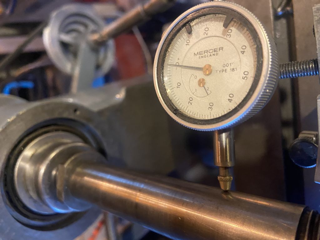
      Putting the dial indicator on the spindle I get 0.001 runout.

      03b6b091-74ac-469e-b31d-73394aabf5e8.jpeg

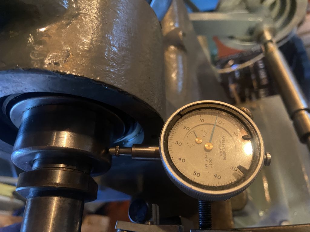
      on the flange (?) of the spindle, I actually get more runout, about 0.00175

      80bd5bc0-e889-4094-8932-e21726c5f918.jpeg

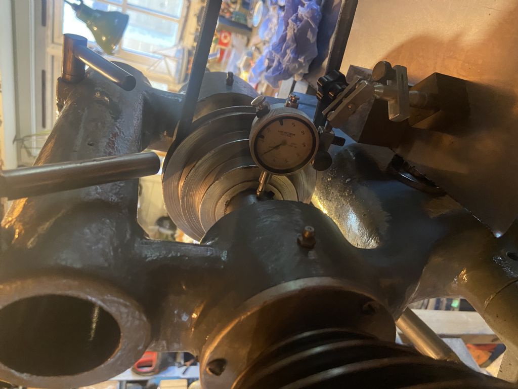
      But interestingly, on the spindle near the *rear* bearing I seem to get no perceptible runout…

      50a2b975-9f1e-4036-897d-e66ce1d06948.jpeg

      All this seems to indicate that the front bearing isn’t quite seated correctly, or is not adjusted / malfunctioning.

      I suppose the spindle could be bent.

      I didn’t manage to get the front bearing off when cleaning up the parts. It was well and truly stuck on the spindle and I didn’t want to bash it and risk damaging it. I don’t really know how to remove it.

      Spindle out and reseat the front bearing?

      I have read Ketan’s advice on preload and heating, that was interesting but I wasn’t sure it was directly relevant to this.

      Thanks

      Steve

      Advert
      #11069
      Steve355
      Participant
        @steve355
        #577959
        Dave Halford
        Participant
          @davehalford22513

          What runout does the arbour show?

          The drive pullies will show more than 1 thou runout and the belts won't care.

          BTW there are some £25 gear cutters out there that have a lot more run out than that.


          When you cleaned the bearing did you spin it dry on the shaft? Damaged ones will catch.

          Whats the end float on the shaft?

          Edited By Dave Halford on 01/01/2022 17:47:43

          #577961
          Steve355
          Participant
            @steve355

            Looks like I fixed it, disassembled, cleaned it all up, put it back together very carefully. Now I’m getting less that 0.0005 runout at the spindle, which is probably surface imperfections.

            The mill still makes a throbbing noise though, but the surface finish looks a lot better.

            Steve

            #577962
            Steve355
            Participant
              @steve355
              Posted by Steve355 on 01/01/2022 17:46:05:

              Looks like I fixed it, disassembled, cleaned it all up, put it back together very carefully. Now I’m getting less that 0.0005 runout at the ARBOUR, which is probably surface imperfections.

              The mill still makes a throbbing noise though, but the surface finish looks a lot better.

              Steve

              Corrected!

              #577964
              Anonymous

                All cutters have some run out. On a horizontal mill the depth of cut is normally far greater than runout so it is not a problem. When I first used my horizontal mill it chattered, and the whole mill shook. Impressive given that it weighs the best part of 2 tons. The cure was simple; double the feedrate so that the cutter teeth were cutting, not rubbing. I use an absolute minimum chip load of 4 thou/tooth.

                Andrew

                #577991
                Steve355
                Participant
                  @steve355
                  Posted by Andrew Johnston on 01/01/2022 18:05:34:

                  All cutters have some run out. On a horizontal mill the depth of cut is normally far greater than runout so it is not a problem. When I first used my horizontal mill it chattered, and the whole mill shook. Impressive given that it weighs the best part of 2 tons. The cure was simple; double the feedrate so that the cutter teeth were cutting, not rubbing. I use an absolute minimum chip load of 4 thou/tooth.

                  Andrew

                  I’m struggling a bit with the speeds, feeds and chip load

                  it has 3 speeds, 250, 500, and 850 rpm

                  To get a chip load of 0.004 at 250 rpm with say a 12 tooth cutter, apparently I need 10 inches per min. It seems much slower than that. Perhaps I’m not understanding it.

                  #577995
                  Anonymous

                    Those speeds are quite high for HSS side and face cutters. Let's assume a 3" diameter cutter. A rule of thumb for a HSS cutter in low carbon steel is 100 feet per minute. For a 3" diameter cutter that equates to 106rpm.

                    Feed rate = chip load x number of teeth x rpm

                    So for the numbers given, 0.004" chip load, 12 teeth and 250rpm we get a feedrate of 12". That's quite high, my (metric) horizontal only goes to 400mm/min.

                    Ideally the arbor speeds need to be reduced. I run side and face cutters, and slitting saws, from about 60rpm to 120rpm in steel.

                    Andrew

                    #577999
                    Bazyle
                    Participant
                      @bazyle

                      Hang on , isn't 400mm/min faster ie about 16in per min.

                      But as your calculations have shown if you have that many teeth you have to move it fast to keep the 4thou per tooth. Since you don't want to drop below 2 thou per cut to avoid rubbing if it isn't dead concentric you have to move the table at least 6in per min.
                      Larger mills run slower rpm but that is to enable big cutters to be used, no to slow production down. 250 rpm is about right for a 3in cutter. The only other limitation is the hp of the motor and can it do the work.

                      #578018
                      JasonB
                      Moderator
                        @jasonb

                        Out of interest as this is a small machine what is the arbor diameter? Could be 3/4" on a machine this size so you may be better off coming down to smaller dia cutters then the spindle speed will be closer to what is needed.

                        Smaller dia cutter would also suit the lower power of the smaller machine

                        Does make you wonder why it has a lowest speed of 250rpm as that would mean you should be using cutters of about 1.5" dia max if sticking to the 100ft/min rule of thumb.

                        Edited By JasonB on 02/01/2022 07:51:11

                        #578022
                        Steve355
                        Participant
                          @steve355
                          Posted by JasonB on 02/01/2022 07:42:56:

                          Out of interest as this is a small machine what is the arbor diameter? Could be 3/4" on a machine this size so you may be better off coming down to smaller dia cutters then the spindle speed will be closer to what is needed.

                          Smaller dia cutter would also suit the lower power of the smaller machine

                          Does make you wonder why it has a lowest speed of 250rpm as that would mean you should be using cutters of about 1.5" dia max if sticking to the 100ft/min rule of thumb.

                          Edited By JasonB on 02/01/2022 07:51:11

                          The arbor diameter is 1”.

                          However, it makes more sense on reading the original sales literature. The Burke #4 had a lowest speed of 66rpm. But the motor and entire countershaft assembly is not original. It has obviously been replaced by someone who either couldn’t source suitable parts or didn’t know what they were doing. Originally the mill had a geared motor, I’d bet that ran at a nice low shaft rpm. The current one runs at a typical 1400 rpm or whatever (haven’t measured it yet).

                          I think I’m going to have to sort this out somehow.

                          #578025
                          Anonymous
                            Posted by Bazyle on 01/01/2022 23:25:41:

                            Hang on , isn't 400mm/min faster ie about 16in per min.

                            Correct. I was simply saying that the maximum feedrate on my mill is 16"/min, so a feed of 12"/min is at the high end of the feedrate range on my mill. For completeness the minimum feedrate on my mill is 0.4"/min.

                            A spindle speed of 250rpm seems awfully high for a 3" diameter HSS cutter. I'd be running at around 100rpm in low carbon steel, and lower still in cast iron or alloy steels.

                            As stated, the sales literature slowest speed of 66rpm is more like what I would expect for a horizontal mill. For comparisonj the speed range on my mill is 30rpm to 1200rpm, although it does have a dual speed motor.

                            Andrew

                            #578033
                            JasonB
                            Moderator
                              @jasonb

                              Yes I did look and see that a No4 had a geared head motor, with the 66rpm low speed and you saying you have 250rpm that would probably mean the gears in the head gave a 4:1 reduction. You will either have to add a countershaft or go the VFD route to get that speed down to something that won't overspeed the cutters.

                              #578048
                              Clive Foster
                              Participant
                                @clivefoster55965

                                +1 for what Jason says about re-engineering the countershaft.

                                Time to hunt down the poly-vee / multigroove belt and pulley catalogues to get something compact sorted out. Rule of thumb with polly-vee is that pulley OD can be less than half the diameter of vee belt ones for same power transmission. Multigroove pulleys are much easier to make than Vee too. Just need to sort out a decent bed stop system on the lathe to get the groove spacing right. A lump bolted to the bed and a set of spacers works fine.

                                If space is limited I'm rather partial to the "back belt" system that mimics the operating principles of a lathe back gear. Two identical large and small pulley pairs. One pair bolted together running on a countershaft. The other pair has one free running and one fixed to the drive input shaft. Free running pulley has the output pulley bolted to it. If the motor has an adequately long shaft you can do a right neat job by fixing a sleeve to the motor shaft to carry the three concentric pulley set viz fixed input drive and free running output pair. For low powers, 1 hp range, the official belt sizes look stupid skinny!

                                #578058
                                Steve355
                                Participant
                                  @steve355

                                  Tbh I am tempted by the VFD route! I have put a lot of work into this machine and I want to use it, starting a new countershaft project wasn’t on my list But I will have a think about it, as you say there may be an back gear type solution.
                                  😢

                                  #578073
                                  Steve355
                                  Participant
                                    @steve355

                                    I just measured the auto-feed rate at 250 rpm – 3 inches per minute. So at 66 rpm it would be unbelievably slow. Something doesn’t seem right….

                                    #578076
                                    JasonB
                                    Moderator
                                      @jasonb

                                      Was that with the feed pullies in their slowest setting?

                                      I's only slow if using a cutter with lots of teeth, I'm sure Andrew will post a pic of a single point cutter that would be feed at 1"/min to give 0.004" chip load.

                                      Edited By JasonB on 02/01/2022 12:26:40

                                      #578078
                                      Steve355
                                      Participant
                                        @steve355
                                        Posted by JasonB on 02/01/2022 12:24:20:

                                        Was that with the feed pullies in their slowest setting?

                                        Yes.

                                        I need to understand this calculation!

                                        #578099
                                        Anonymous

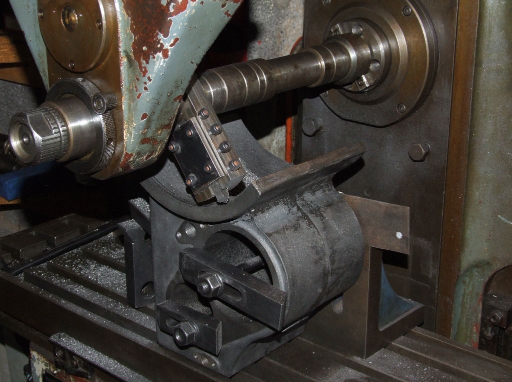
                                          Home made flycutter with single point HSS toolbit, 8.6" diameter, running at 54rpm in cast iron:

                                          cylinder_flange_me.jpg

                                          Roughing cuts were 50 thou deep and 15 thou per rev feed. For the finishing cut I slowed the feed to 4 thou per rev. Took ages as 0.004" per rev at 54rpm is 0.216"/min. Made worse as I was feeding in Y which means it was by hand – power feed on X only. Made slightly easier as the mill is metric, and since 0.004" is about 0.1mm it was one big division on the dial per clonk.

                                          Andrew

                                          #578100
                                          Bazyle
                                          Participant
                                            @bazyle

                                            Calculations
                                            Speed of tooth through metal = RPM x pi x diameter.
                                            If the diameter is in inches your speed is of course in inches so by convention measure it in feet.
                                            The number of teeth doesn't matter for this bit. target for mild steel is somewhere between 100 and 200 ft/min. Us amateurs will be in less of a hurry than the professionals and you might want to have flood coolant for the higher rates.

                                            Movement of the table is a separate consideration from the above, which can seem odd but it is.
                                            Here number of teeth matter, but diameter doesn't.
                                            So RPM x No of teeth gives you the number of cuts per minute.
                                            Each cut is say 4 thou but we want to work in inches or feet – so 0.004 in.
                                            That gives you RPM x Teeth x cut which is the feed speed in inches/minute you need to move at to compare with the rates your mill feed provides.

                                            If you are winding the handle manually you probably wan to convert it to inches per second so divide by 60, then multiply by the tpi of your leadscrew. Then you really get a feel of how fast it is and remember if you wobble in your turning you will get grabs or rubbing.

                                            All this can be applied to vertical cutters too and remember not to climb mill on an old machine.

                                            (now I'm off to find the manuals for my machine as I'm not sure I've been going as quick as I should)

                                            #578105
                                            Steve355
                                            Participant
                                              @steve355
                                              Posted by Bazyle on 02/01/2022 14:34:15:

                                              Calculations
                                              Speed of tooth through metal = RPM x pi x diameter.
                                              If the diameter is in inches your speed is of course in inches so by convention measure it in feet.
                                              The number of teeth doesn't matter for this bit. target for mild steel is somewhere between 100 and 200 ft/min. Us amateurs will be in less of a hurry than the professionals and you might want to have flood coolant for the higher rates.

                                              Movement of the table is a separate consideration from the above, which can seem odd but it is.
                                              Here number of teeth matter, but diameter doesn't.
                                              So RPM x No of teeth gives you the number of cuts per minute.
                                              Each cut is say 4 thou but we want to work in inches or feet – so 0.004 in.
                                              That gives you RPM x Teeth x cut which is the feed speed in inches/minute you need to move at to compare with the rates your mill feed provides.

                                              If you are winding the handle manually you probably wan to convert it to inches per second so divide by 60, then multiply by the tpi of your leadscrew. Then you really get a feel of how fast it is and remember if you wobble in your turning you will get grabs or rubbing.

                                              All this can be applied to vertical cutters too and remember not to climb mill on an old machine.

                                              (now I'm off to find the manuals for my machine as I'm not sure I've been going as quick as I should)

                                              ahhh, so the 0.004 is LENGTH of cut, not depth of cut. I think I get it now!

                                              so if I had say 250rpm and a 20 tooth cutter, and I wanted cuts of 0.004, I’d need 20 ipm feed.

                                              if my mill did 66 rpm and it’s designed to, with a 20 tooth cutter, and I wanted 0.004 cuts, I’d need 5.28 ipm feed.

                                              But the fastest it can go is 3 ipm at 250rpm.

                                              Something is not right about my mill!

                                              Edited By Steve355 on 02/01/2022 15:00:25

                                              #578112
                                              JasonB
                                              Moderator
                                                @jasonb
                                                Posted by Steve355 on 02/01/2022 14:59:36:

                                                But the fastest it can go is 3 ipm at 250rpm.

                                                Something is not right about my mill!

                                                You said the 3" was with it in the slowest speed of the feed pullies, what is it in the fastest?

                                                #578204
                                                Steve355
                                                Participant
                                                  @steve355

                                                  3” is with the pulley that gives 250rpm on the spindle

                                                  Obviously with the spindle running faster the feed will be quicker. But as I understand it I need the spindle running slower (say 120 rpm) and the feed running faster, or at least the same.

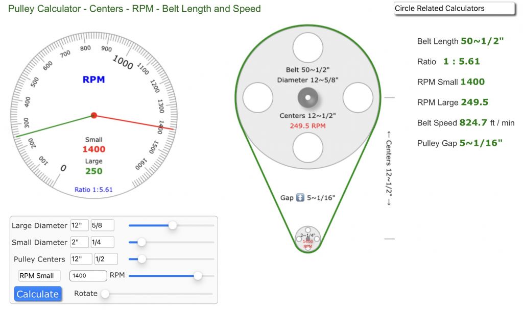
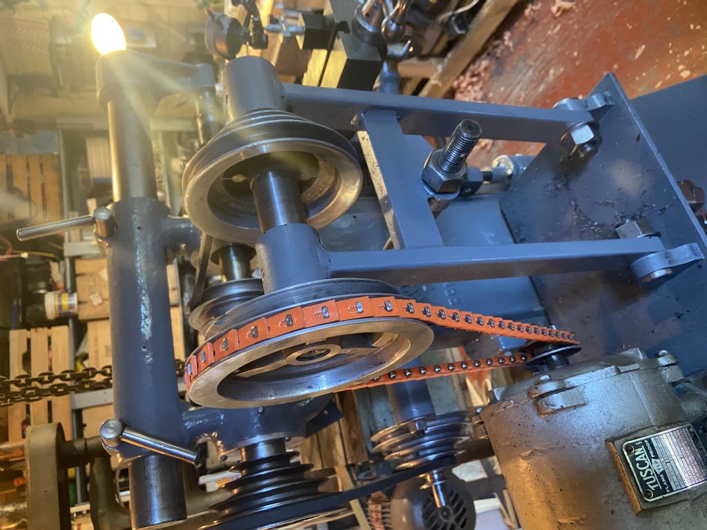
                                                  Right now it’s like this, with the motor pulley being the small pulley and the large pulley being the driver for the countershaft… this gives 250rpm at the spindle.

                                                  67ce28ad-2f0d-4d32-a09f-99695df7112b.jpeg

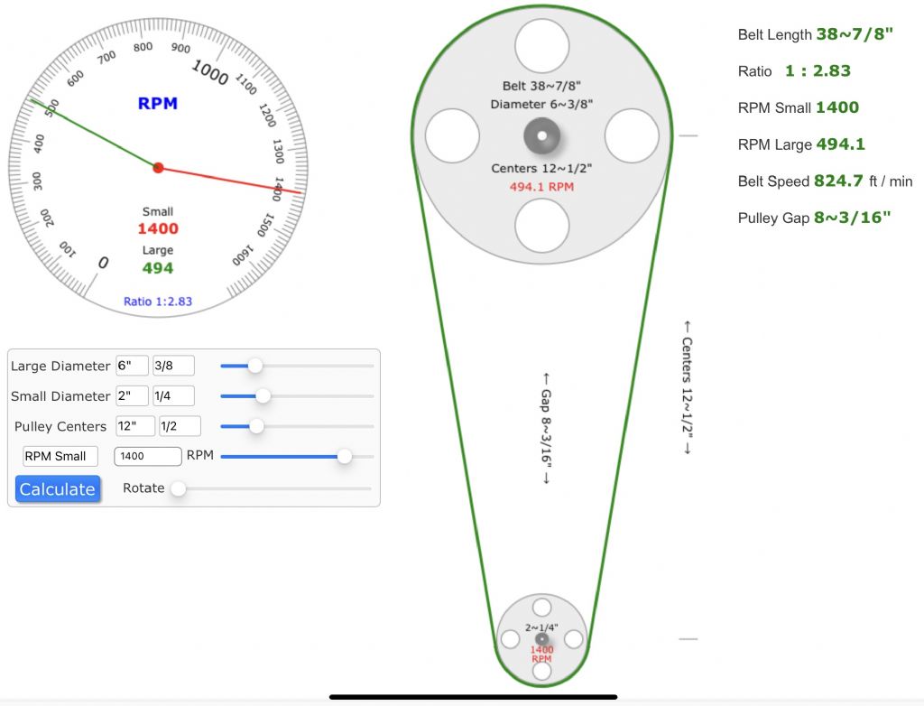
                                                  Perhaps the easiest/cheapest way to fix it is to increase the size of the countershaft pulley…

                                                  0177e629-9a23-4a80-b3bc-c9d8f6e5260a.jpeg

                                                  Which would give 125 rpm ish at the spindle, a lot closer to the ballpark needed. But the feed would be 1.5 ipm.

                                                  I saw an advert for later versions of the mill, which had a hydraulic system for feeding the table. Perhaps that was a solution to the inherent difficulty of having a suitable feed rate and low spindle speed.


                                                  thoughts appreciated 🥺


                                                  Edited By Steve355 on 03/01/2022 10:40:18

                                                  #578208
                                                  Dave S
                                                  Participant
                                                    @daves59043

                                                    How is the feed taken off?

                                                    Could you change the spindle pulley and a subsequent feed pulley to give a more appropriate ratio?

                                                    Dave

                                                    #578217
                                                    Steve355
                                                    Participant
                                                      @steve355
                                                      Posted by Dave S on 03/01/2022 10:49:20:

                                                      How is the feed taken off?

                                                      Could you change the spindle pulley and a subsequent feed pulley to give a more appropriate ratio?

                                                      Dave

                                                      I don’t think so, the feed pulley for the spindle is about as small as it can be and the spindle pulley is about as big as it can reasonably be. See pic below.

                                                      I feel a vfd coming on, wallet is getting worried.

                                                      b89dee39-b1b2-4d48-8811-436de779fb9c.jpeg

                                                      Edited By JasonB on 03/01/2022 13:27:46

                                                    Viewing 25 posts - 1 through 25 (of 55 total)
                                                    • Please log in to reply to this topic. Registering is free and easy using the links on the menu at the top of this page.

                                                    Advert

                                                    Latest Replies

                                                    Home Forums Beginners questions Topics

                                                    Viewing 25 topics - 1 through 25 (of 25 total)
                                                    Viewing 25 topics - 1 through 25 (of 25 total)

                                                    View full reply list.

                                                    Advert

                                                    Newsletter Sign-up