Highly accurate machined parts with excellent surface finishes like those are tough enough. Designing your own specialized parts starting with a blank piece of paper or computer screen and making them good looking, functional as well as in proper proportion is something else. Very few in my opinion have that combined set of skills Gray. My best compliment I could use for anyone's work would be to say there as good as anything George Thomas did. I think you've set a new bench mark for what my best compliment would be now.
Have you given any thought about producing a volume II of your Projects For Your Workshop book?
Thank you all for your kind endorsements of my work. This project has been a test for man and machines. While the machines handled the work with no trouble. I have found this project has taken me a long time to achieve.
I was fortunate enough to call GHT my friend and visited him many times at Milton Grange. I owe a lot of my skills to his writings and his meticulous approach to planning his projects. He was a fount of knowledge when it came to engineering, and his woodworking skills with mortice and tenon joints would put many a toolmaker to shame.
As regards a volume II I regret to say that this is out of my control. Chris Deith was the instigator of the first volume, which came totally out of the blue when he rang me one day at work with the suggestion of a book. That was well over 13 years ago now and approximately 50 articles ago. I suspect with his passing that will be the end of any future volumes.
It has been a while since I last posted anything on this thread. I have just completed a couple of items. The first is an adjustable lever that fits inside the belt cover and thus saves me looking for an Allen key. Having to search for an Allen key is one of my pet hates when it comes to using my machines.
The Lever above is shown in the locked position and is so designed that the guard will only close in this position.
This image shows the lever released. One thing that no longer happens is the Pulley tilting over as it did when using a capscrew to lock the assembly. That is because an M6 stud now replaces that capscrew and thus keeps everything vertical.
Changing speeds is no longer a hassle of trying to get a belt over a constantly moving pulley.
The next item is something that came about after a suggestion and a PDF from John Slater. The PDF was a set of drawings by Stefan Gotteswinter for a Low Level Clocking attachment. I am beginning to think John is clairvoyant as this is something I had been thinking about for sometime for the Proxxon.
Whilst Stefan’s design was for a simpler sliding mechanism. A rabbit hole was introduced with regards to “it would be a good idea if the attachment had a fine adjustment”. While I disappeared down one rabbit hole John came up with a different design.
However I wanted something specific to the Proxxon, and as such had a restricted swing before the attachment hit the Column of the machine. John having the larger Sieg mill needed a greater swing and had the luxury of more room under the spindle.
Not fancying having to screw the clock from one end to the other. There is a spring loaded quick acting nut fitted. Which allows rapid adjustments without the need for the fine adjustment. In Stefan’s original design he incorporated an eccentric arbor to mount the unit on. This allows the stylus of the clock to be set on the machine centreline. His design needed the clock to moved out of the way for each adjustment. My design has a split clamp to allow adjustment and a shoulder which stops the whole unit dropping off the end of the arbor during adjustment. As such the clock is much easier to set-up on centreline.
This shows the unit in the machine.
As can be seen from the proximity of the clock dial to the slide bar this is a very compact design.
This last view shows the quick acting nut button. Pressing this disengages the feedscrew and allows rapid adjustments. The clock fitted is one of the shortest on the market that I could find, without spending a fortune. As this clock will remain fitted to this unit.
If the Moderators think this last item warrants a new thread then I am good with that.
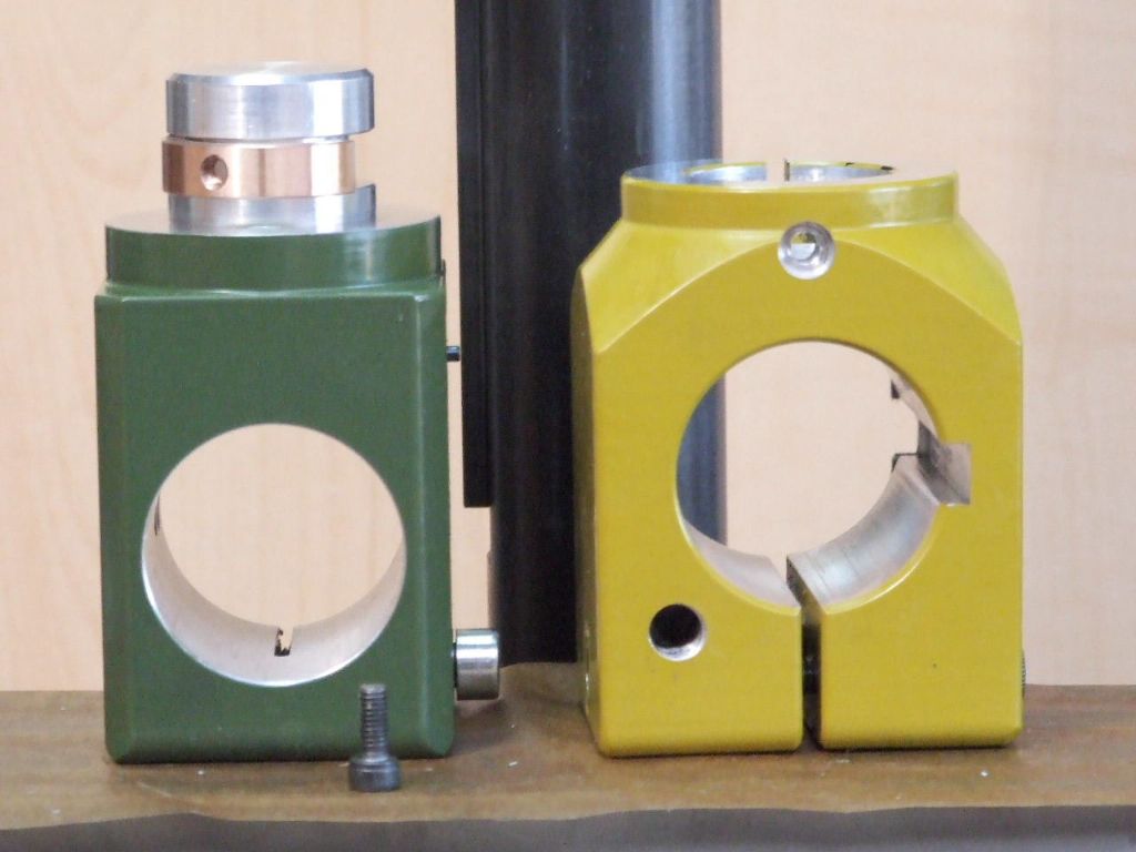
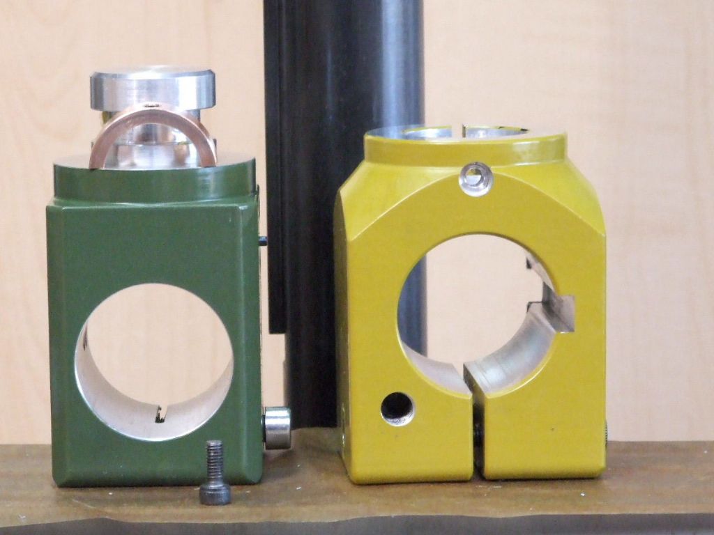
One thing I had noticed when “Tramming” the milling head was that there was a tendency for the Quill housing to work it’s way out of the Slider.
To solve this I have made a semicircular Bronze Key which fits in the groove machined to provide clearance for the M6 Cap screw which clamps everything up when the Milling head is dead true.
The key is held in place with a single M4 Cap screw. The counterbore for this can be seen in the top face of the Slider.
The Bronze ring provided two Keys which was handy as I have a spare milling head.
One other thing I need to make is a Tailstock support for the Emco Dividing attachment which I have adapted to fit this machine. This will then give me the machine that I want.
Regards
Gray,
Hi Graham,
I’ve got a similar “nod” problem with my Proxxon Mill & was wondering if you happen to remember the approximate size of the bronze ring you made?
Otherwise do you happen to remember roughly what the “Slider” OD was?
I need to order some bronze but didn’t want to have to strip down the Mill to figure out the diameters needed.
Just need some rough numbers so I know what to chase.
For those like Colin who wish to carry out his modification. Below is attached a work in progress drawing. I thought I had better add this now as I shall probably forget.