Adaptation of the Proxxon Milling machine

Advert

Adaptation of the Proxxon Milling machine

Home Forums Manual machine tools Adaptation of the Proxxon Milling machine

Viewing 25 posts - 26 through 50 (of 61 total)
  • Author
    Posts
  • #625675
    Bountyboy
    Participant
      @bountyboy

      Fabulous work Gray, a life time of refining your design and machining skills. I’ve just purchased your book, Projects for your workshop, from RDG (early Christmas present). Hoping to make the spindle lock for the EMCO FB2.

      Looking forward to seeing more workshop wizardry!

      Advert
      #626038
      Graham Meek
      Participant
        @grahammeek88282
        Posted by Dick H on 21/12/2022 17:15:33:

        I have a Proxxon FF230 mini (nano?) mill, Can someone please tell me how to remove the stepped pulley at the top of the spindle? There is a very small grub screw to be removed and then I assumed the pulley should be able to be pulled off. Am I missing something? Is it screwed on or has someone used a locking compound on the shaft? I don´t want to use too much umph on it.

        Dick.

        Hello Dick,

        My apologies for not responding sooner. The Pulley unscrews once you have removed the M3 grubscrew. You will need a Peg spanner to go in the two holes in the pulley. I made mine from a short piece of aluminium bar and two short lengths of silver steel.

        When replacing the pulley do not over tighten the grubscrew or the pulley will wobble. Also bear in mind that this pulley also adjusts bearing pre-load which does not want to be excessive. Just enough to eliminate any endwise play.

        When I made the new ER 20 spindle for my Proxxon I altered this design. I introduced a separate circular nut. This nut adjusts the bearings while the Pulley locks the adjustment and the assembly. I hope in due course to publish details on this mod, as well as the spindle mod.

        Regards

        Gray,

        #626044
        Dick H
        Participant
          @dickh

          Many thanks. I couldn´t see from the exploded diagram what was going on. I´ll have another go over Christmas.

          Regards,

          Dick

          #626067
          Graham Meek
          Participant
            @grahammeek88282

            Hello Dick,

            I forgot to mention Proxxon have started using Loctite Thread Locking compound in more recent times.

            Regards

            Gray,

            #626073
            Dick H
            Participant
              @dickh

              It is at least 15 years old, so i hope not, else I'll have to get a flame to it. Thanks again.

              Dick.

              #629341
              Graham Meek
              Participant
                @grahammeek88282

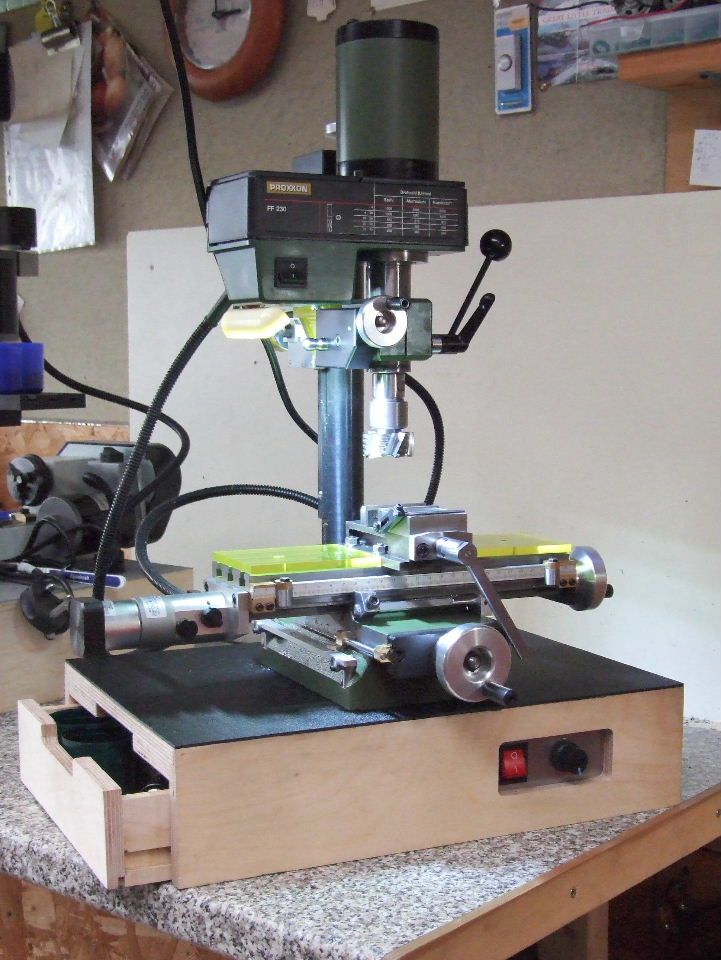
                proxxon base board.jpg

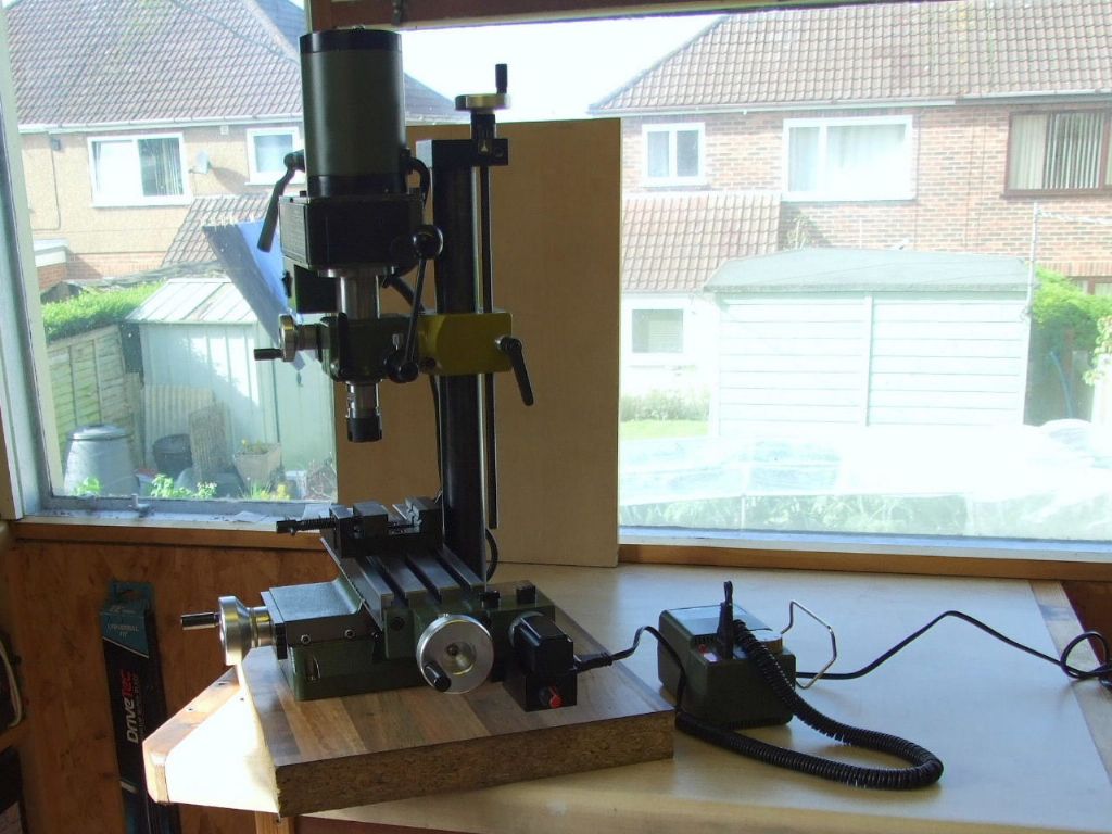
                The Mounting Board for the Proxxon mill has finally been fitted. The Switch and Knob are for the variable power feed. This now has a dedicated 12v Power Supply feeding a PWM unit. While I have more variation of the feed rate lower down with this set-up. It has been at the expense of a reduced top feed rate. However due to use of the Proxxon plug arrangement on the table feed motor. It is still possible to substitute the Proxxon power supply if needed, so I have the best of both worlds.

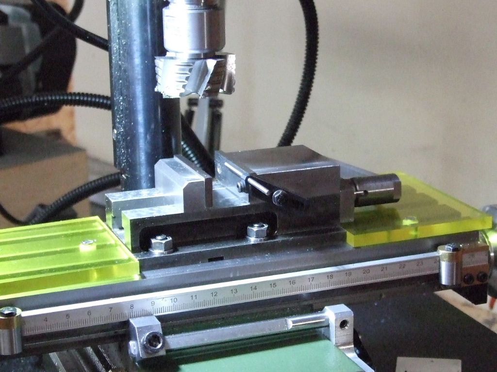
                proxxon vice stop-1.jpg

                Talking to a friend recently I was saying I was making a milling machine vice stop for the Proxxon mill. My listener was not familiar with this term or set-up. These type of stops are used widely in industry and I have used countless hundreds in my career. Up until I had completed this unit I had been managing to do jobs with a stop mounted in the tee-slot off the milling table.

                However the manufacture of the Table Protectors to help keep the table clear of swarf made using this type of stop a nuisance. Plus when using the vice as shown above there is no Tee slot to use such a stop.

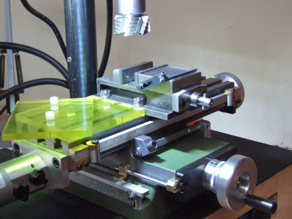
                proxxon vice stop & table protectors.jpg

                This view shows the construction of the table protectors and the stowing position for the stop when this is not being used. The spigot positions are such that the protectors will also fit across the table when using the Emco Compact 5 rotary table.

                The Acrylic is Yellowish and it is not the camera. This was some off-cuts I had left over from an assembly tool which used UV light and this particular Acrylic blocked the UV.

                Regards

                Gray,

                #633891
                Graham Meek
                Participant
                  @grahammeek88282

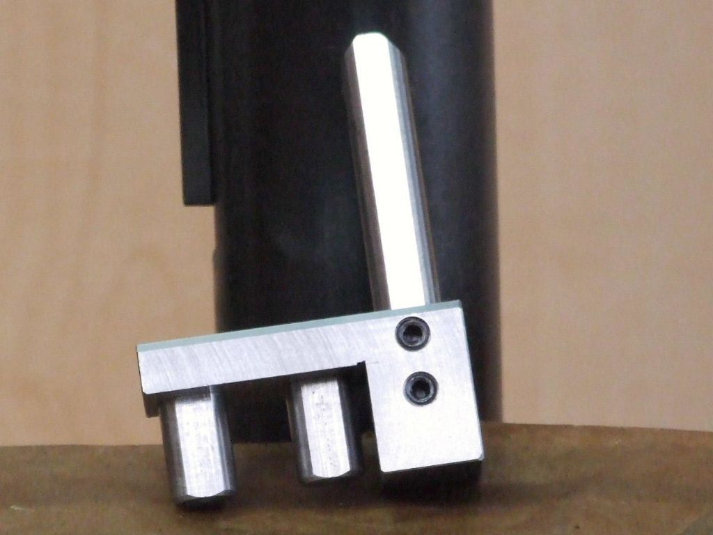
                  boring head extender block.jpg

                  exctender block fitted.jpg

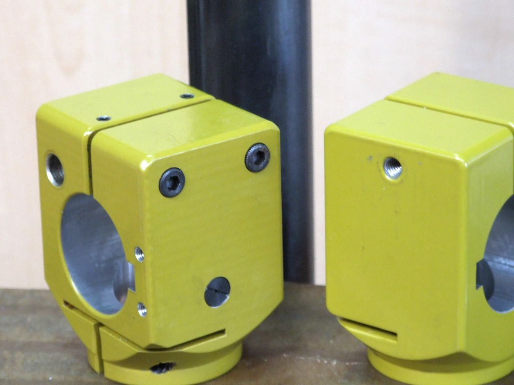
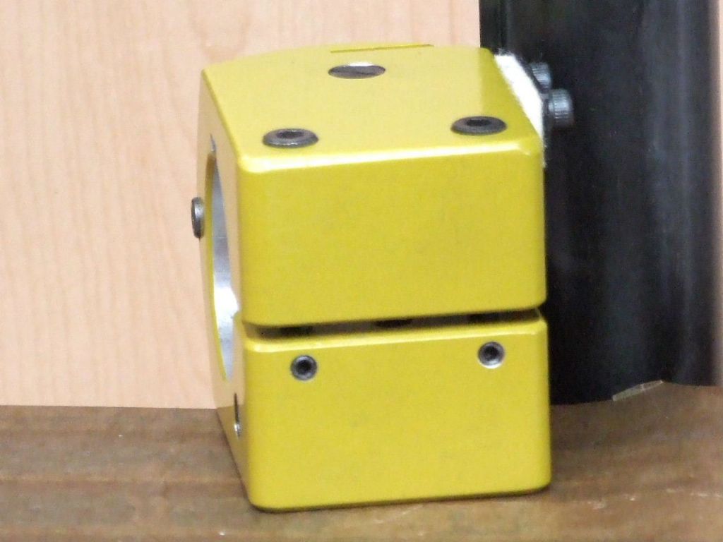
                  A while back in this thread I had to use my smaller Boring head to extend the range of my Boring and Facing head. A set-up which I was not impressed with, but it did do the job. I have since made a dedicated Extender block for the B&F Head, shown above.

                  Those Eagle Eyed among you might notice the two dowels in the Gib strip. This forms part of a further refinement for this machine and I will shortly post more details about this.

                  Regards

                  Gray,

                  #634013
                  Graham Meek
                  Participant
                    @grahammeek88282

                    column adjustment fitted.jpg

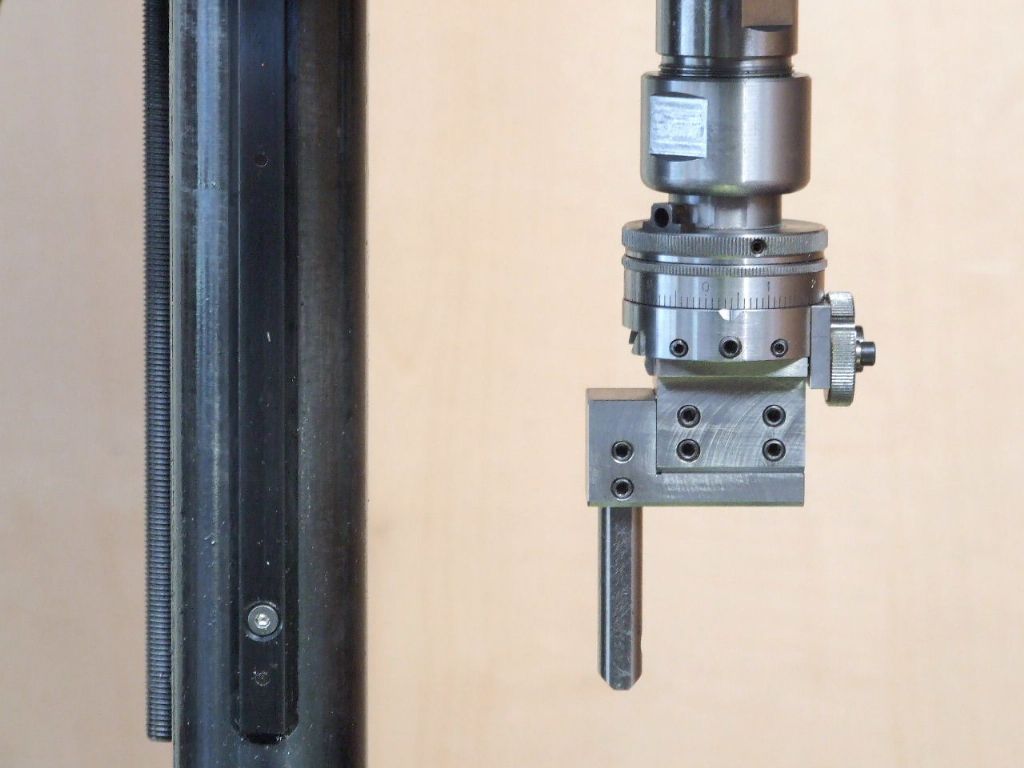
                    I did think when I purchased this machine, given it's country of origin. That I would not have a lot to do to get this machine to where I wanted it. The Guide strip or Key down the Column was one area I thought would not need any attention. Unfortunately this time I was wrong.

                    The Guide strip is held onto the Column with countersunk Allen cap screws. Experience has told me that the heads on these screws are seldom concentric with the thread. The head will therefore tend to move sideways the item being secured.

                    This was one of the issues with this machine. While the Guide strip was relatively straight, 0.05 mm bend over the 290 mm. When fitted to the Column there was helical run-out of around 0.2 mm from end to end.

                    Straightening the Guide strip 0.005 mm over the 290 mm and counterboring the countersunk holes to take shallow head M3 cap screws, eradicated the helical error. To make sure the Guide strip did not move during use four 2.5 mm hardened dowels were fitted at 90 mm centres.

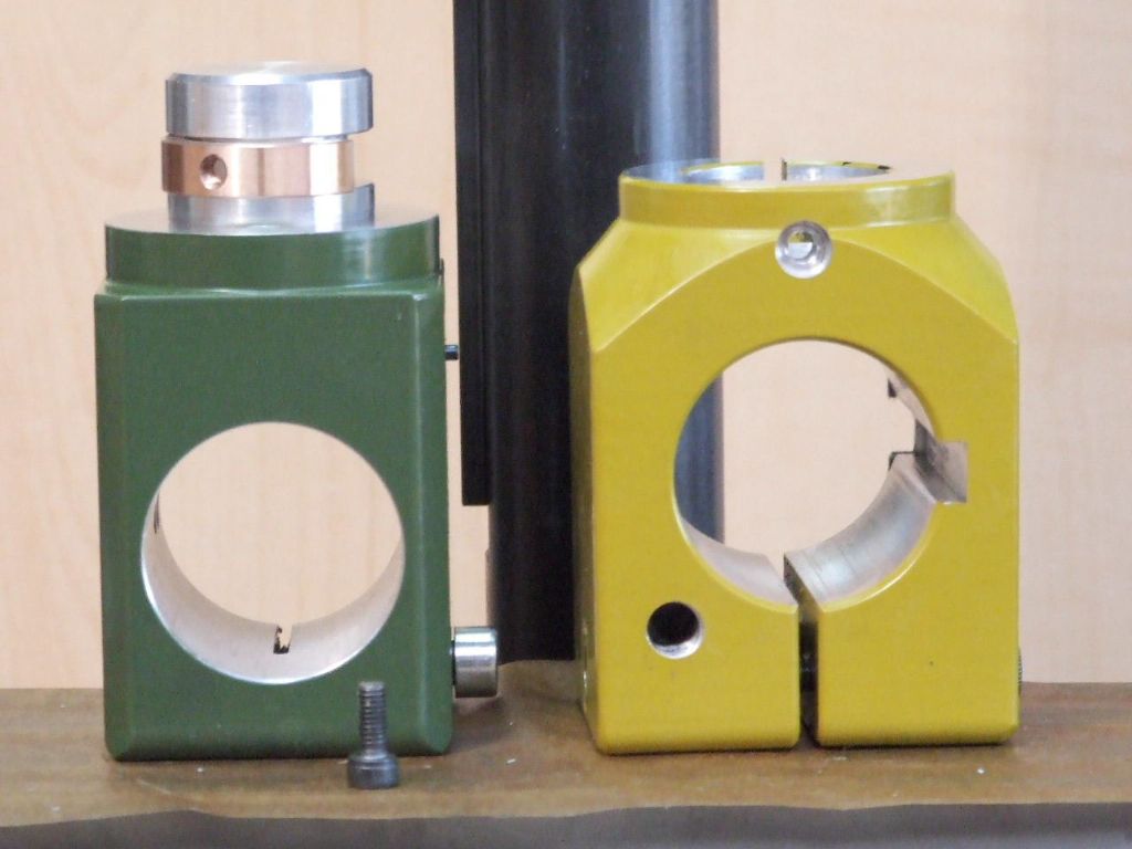
                    In the above photograph you will see two additional M5 cap screws have been added to adjust the clearance between the Column and the Slider. Next to these is a large slotted screw head. This carries an eccentrically mounted ball bearing race which eliminates the play between the Slider and the Guide strip.

                    bearing just showing in keyway.jpg

                    This shot shows the bearing just showing in the sidewall of the keyway. Note there is no loss of bearing area on the internal surface of the Slider to Column interface.

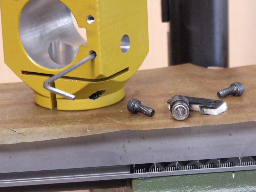
                    gib adjuster parts and wiper assy.jpg

                    These are the adjuster parts and wiper assembly to keep swarf out. The Allen key is in an M4 grubscrew which locks the eccentric adjuster via a copper pad.

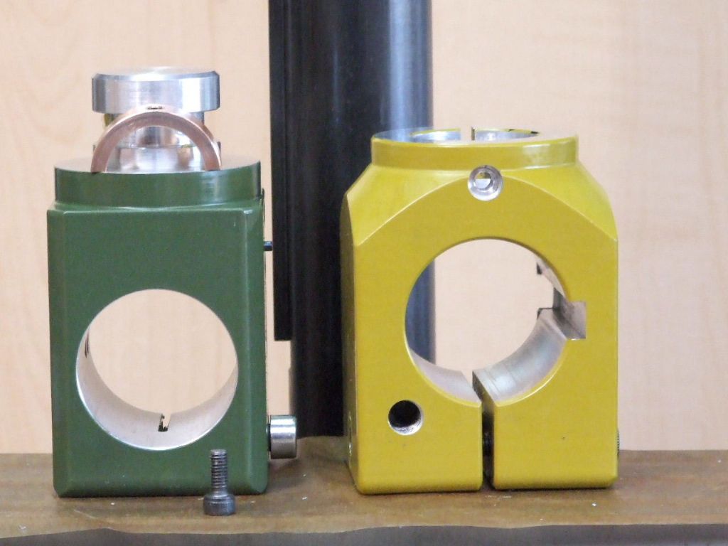
                    modifications shown clearly.jpg

                    This shows the basic modifications . The two tapped holes on the top of the Slider are to lock the M5 cap screws after adjustment. There is a Delrin pad beneath the M4 grubscrews.

                    column adjusters locking screws.jpg

                    These modifications have totally transformed the machine in use and have been well worth the extra work.

                    There is one more small mod which I will detail later.

                    Regards

                    Gray,

                    #634095
                    duncan webster 1
                    Participant
                      @duncanwebster1

                      Just a caution, I bought 2 of those little Swan neck lights, but I've binned them. They have a capacitor to limit the current, but the plug wasn't handed, so the 240v could easily be applied to one end of the leds via a very thin wire inside the metal neck. No earth, no double insulation. Potentially deadly

                      #634150
                      Graham Meek
                      Participant
                        @grahammeek88282

                        Hi Duncan,

                        I have three such lights in use and as yet I have not had any problem with them. These lights came with a slotted tag on both wires which were the same colour.

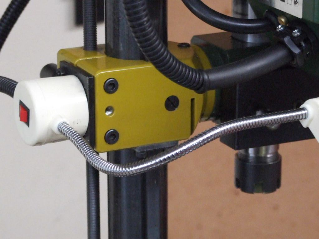
                        It is not my final answer to the lighting problem as I does leave a unlit area the other side. I also have to watch how bright a light I use. Too much brightness will induce a migraine. Halo type lights are too bright having tried these.

                        Regards

                        Gray,

                        #634193
                        Graham Meek
                        Participant
                          @grahammeek88282

                          bronze key.jpg

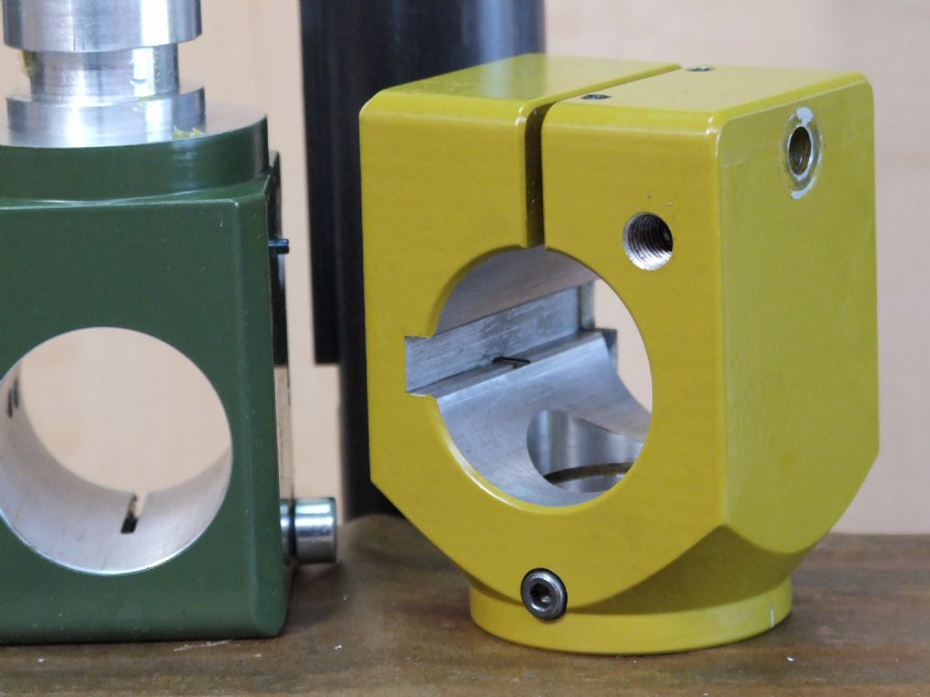
                          One thing I had noticed when "Tramming" the milling head was that there was a tendency for the Quill housing to work it's way out of the Slider.

                          To solve this I have made a semicircular Bronze Key which fits in the groove machined to provide clearance for the M6 Cap screw which clamps everything up when the Milling head is dead true.

                          The key is held in place with a single M4 Cap screw. The counterbore for this can be seen in the top face of the Slider.

                          shape of key.jpg

                          The Bronze ring provided two Keys which was handy as I have a spare milling head.

                          One other thing I need to make is a Tailstock support for the Emco Dividing attachment which I have adapted to fit this machine. This will then give me the machine that I want.

                          Regards

                          Gray,

                          #634204
                          Ian P
                          Participant
                            @ianp
                            Posted by duncan webster on 18/02/2023 23:37:07:

                            Just a caution, I bought 2 of those little Swan neck lights, but I've binned them. They have a capacitor to limit the current, but the plug wasn't handed, so the 240v could easily be applied to one end of the leds via a very thin wire inside the metal neck. No earth, no double insulation. Potentially deadly

                            Duncan, I dont want to take Grahams thread too far off topic but from your description those work lights should not be on sale in the UK.

                            From the descriptions of the ones being sold on ebay and Amazon I would have assumed that there was a proper SMPS in the magnetic base, if its just a capacitor dropper than I'm appalled! Please can you confirm if that the case?

                            In any event the ones I have seen are being marketed with a USA 2 pin plug so the product is wrong on several levels. But they look downright dangerous.

                            Ian P

                            #634213
                            Graham Meek
                            Participant
                              @grahammeek88282

                              Hi Ian P,

                              I can tell you there is a circular populated Circuit board contained in the plastic cylindrical housing. I cannot say for sure how many components are present.

                              Regards

                              Gray,

                              #634215
                              Ian P
                              Participant
                                @ianp

                                Its quite possible that the PCB contains an PSU with an isolated output but in one sense its irrelevant as almost certainly it will not be compliant with UK regs.

                                I know you have the lights fitted to a machine and in use, so please be careful, I suggest finding some way of adding a ground wire to metal flexy bit.

                                This comes up on Google

                                __________________________________________________________________________________________
                                Are two pin plugs legal in UK?

                                The three-pin/two-pin plug problem also arises if you're a UK retailer or distributor selling devices manufactured in Europe that come to you with a two-pin connector attached. UK law insists that all European electrical products must be converted to a three-pin UK plug before sale or distribution.
                                ——————————————————————————————————————————————————

                                Ian P

                                #634249
                                duncan webster 1
                                Participant
                                  @duncanwebster1

                                  As I said I've binned mine. No switch mode, capacitor. Bought direct from China, not UK stock. You won't know you've got a problem until you're twitching on the floor.

                                  #634271
                                  Kiwi Bloke
                                  Participant
                                    @kiwibloke62605

                                    Gray. Interesting mod, that can be applied to other machines, of course, and beautifully executed, as we've come to expect. Two questions…

                                    1. Why did you choose to use a roller (ball bearing set) to follow the guidance strip/key, rather than fit a gib strip?

                                    2. (Apologies if I've overlooked the answer). Is the column's guide strip/key located in a groove in the column, or just planted on its surface, or on a flat?

                                    #634272
                                    Kiwi Bloke
                                    Participant
                                      @kiwibloke62605

                                      Re the LED lamps: why bin them? It should be fairly easy to convert them to a low-voltage supply. Surely the mechanical hardware is worth a few bob?

                                      #634307
                                      Graham Meek
                                      Participant
                                        @grahammeek88282
                                        Posted by Kiwi Bloke on 20/02/2023 00:35:42:

                                        Re the LED lamps: why bin them? It should be fairly easy to convert them to a low-voltage supply. Surely the mechanical hardware is worth a few bob?

                                        Hi Kiwi Bloke,

                                        My original thoughts were to use two of these lamps either side of the milling head in bespoke units. With more rigid arms. The Flexible arm is good in theory, but does start to droop over time. In the current set-up the head of the light unit is held by a single screw which also holds the internal circuit board of the mill.

                                        This position affords the best option from an operational point of view, but it does not illuminate the X-Axis dial in low ambient light levels. A good point for me is I don't run the risk of the light catching me in the eye and triggering a migraine.

                                        Regards

                                        Gray,

                                        #634435
                                        Kiwi Bloke
                                        Participant
                                          @kiwibloke62605

                                          Gray, did you overlook my previous post?

                                          #634460
                                          Graham Meek
                                          Participant
                                            @grahammeek88282
                                            Posted by Kiwi Bloke on 20/02/2023 00:30:45:

                                            Gray. Interesting mod, that can be applied to other machines, of course, and beautifully executed, as we've come to expect. Two questions…

                                            1. Why did you choose to use a roller (ball bearing set) to follow the guidance strip/key, rather than fit a gib strip?

                                            2. (Apologies if I've overlooked the answer). Is the column's guide strip/key located in a groove in the column, or just planted on its surface, or on a flat?

                                            Hi Kiwi Bloke,

                                            I apologise for not responding before but I did not see this post.

                                            1. To fit a Gib adjustment strip would necessitate opening up the Keyway in the Slider. Twelve months ago when I had my other equipment this would not have been a problem. Today that would be impossible unless I subcontract the job, which is fraught with problems.

                                            Fitting a Gib here would also mean putting the adjustment screws in from the back of the machine.

                                            When the head is unlocked the turning couple due to the weight of the milling head. Tends to concentrate the force at the top of the rear face of the Keyway. This would be directly onto the Gib strip if it was situated here.

                                            The ball race allows the adjustment to come from the opposite side and any droop from the turning couple is taken by a solid face. I also chose the ball race because this would reduce the drag. When compared to a full length Gib strip. It will also tolerates a slight deviation in the Key strip width, due to this being just drawn bar stock.

                                            2. In an ideal world I would have fitted this key in a shallow groove. This does two functions in that it would take out any straightness issues from a bent Key strip. Secondly it is not going to move in use. Plus it would not matter if Countersunk screws are used.

                                            Proxxon have had two different types of Key strip attachment from the components I have in my workshop. Some years back they were attaching the Key strip with M4 Slotted Countersunk screws. This Key strip is planted directly on the Column diameter. The Column on this set-up is of "Drawn" appearance.

                                            Currently there is a flat machined on the Column and the Key strip is held with 3 x M3 Countersunk screws onto this flat. Even here there is a second deviation in that some columns have been turned, while the two new ones I received from Proxxon recently have been "Ground". I have put Ground in inverted commas because I am of the opinion from the finish that this may have been done with a tube linisher. The new Columns do perform better than the old ones.

                                            I hope this helps?

                                            Regards

                                            Gray,


                                            Edited By Graham Meek on 21/02/2023 11:39:21

                                            #634466
                                            duncan webster 1
                                            Participant
                                              @duncanwebster1
                                              Posted by Kiwi Bloke on 20/02/2023 00:35:42:

                                              Re the LED lamps: why bin them? It should be fairly easy to convert them to a low-voltage supply. Surely the mechanical hardware is worth a few bob?

                                              When I say binned, they are in the scrap bin awaiting further use. I did actually modify them by cutting the pcb in the head and so getting them to work on about 20v if I remember correctly, but a refit of the main power supply took away the 20v supply, and so it was a lot easier to start again.

                                              #634517
                                              Kiwi Bloke
                                              Participant
                                                @kiwibloke62605

                                                Gray. Thanks for explaining. It all makes sense. Instructive. Seems Proxxon equipment may be more than a bit like the curate's egg?

                                                Duncan. Glad to hear you also have a scrap/to-be-used-later bin! I hate waste and throwing anything away. My wife tells me it's a problem. I think it's a virtue…

                                                #644300
                                                Graham Meek
                                                Participant
                                                  @grahammeek88282

                                                  proxxon tailstock support.jpg

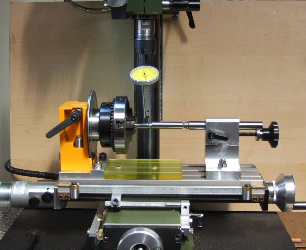
                                                  For some while I have been working on the Tailstock Support to be used in conjunction with the Emco Dividing attachment. I used it recently to make the Eccentric Spindles for the Emco Compact 5 and Unimat 3/4 Lever operated Clamping attachments. One of the Eccentric shafts is being set up in the above photograph.

                                                  The Tailstock body is made in to halves for ease of manufacture. The split line is easily seen in the above picture. Two Button headed dowels locate in the central Tee slot. This automatically locates the tailstock on the same centre-line as the Emco unit. Which also uses two button headed dowels in the same tee slot.

                                                  The tailstock barrel is locked by two brass half pads using the adjustable clamping lever. The barrel currently looks a little over-long, and this may well get shortened sometime in the future, once I have had a chance to use the tailstock a bit more.

                                                  The interchangeable centres uses the usual Unimat location technique but the dimensions are the same as the earlier Unimat SL. I had thought of using the U3/4 dimensions but this would have led to a larger tailstock barrel. This can be a problem when working on smaller pinion gears. Where the gear cutter fouls the tailstock barrel.

                                                  Regards

                                                  Gray,

                                                  #662063
                                                  Graham Meek
                                                  Participant
                                                    @grahammeek88282

                                                    ff 230 mill with new table feed.jpg

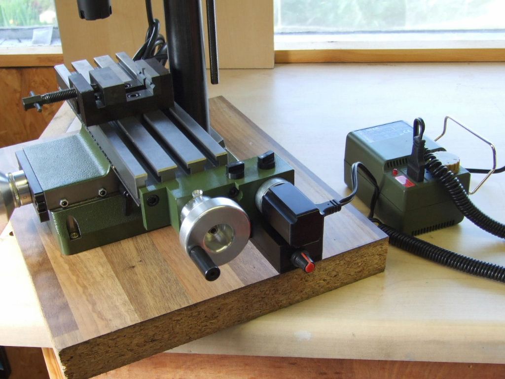
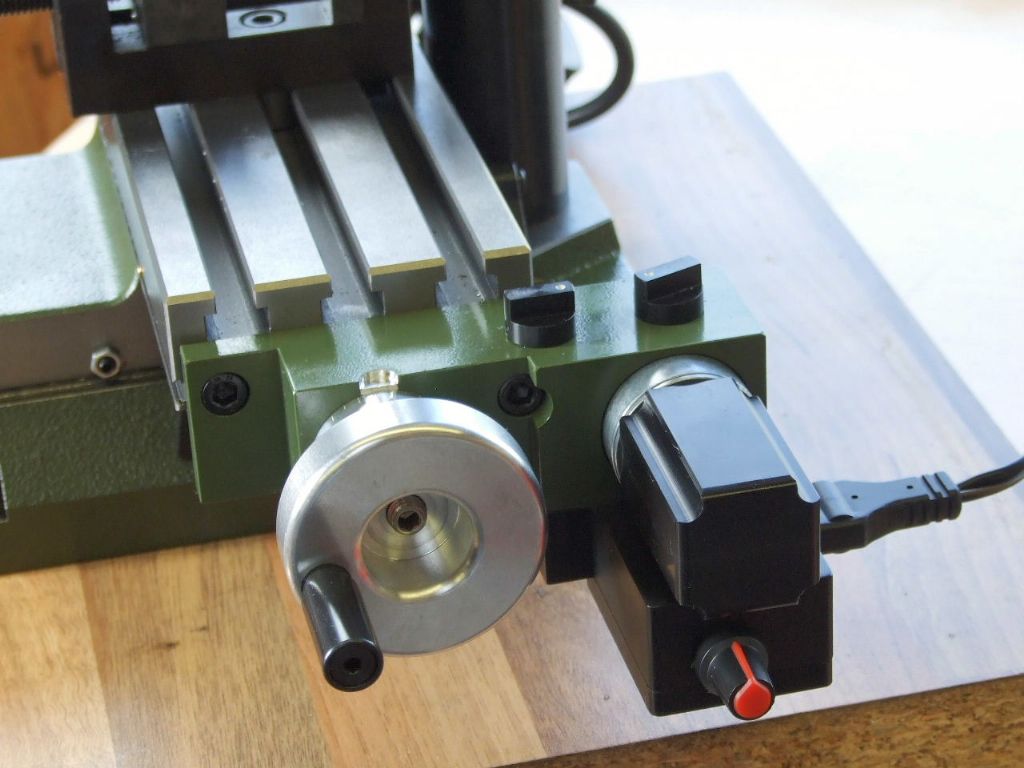
                                                    I have just completed this revised table feed attachment. It was designed with a view to the FF 230 mill requiring no modifications in order to fit the unit. It simly bolts on where the original feedscrew bearing plate fitted.

                                                    ff230 table feed.jpg

                                                    I had some help from John Slater in the form of a small PWM board. The control and "ON-OFF" for the PWM can be seen below the motor housing.

                                                    ff 230 table feed attachment.jpg

                                                    The two knobs on the top of the unit control the direction of travel, (nearest the handwheel), and the clutch to engage the drive to the table.

                                                    Not only is there a variable drive through the PWM, but the Proxxon NG 2e Power supply can also provide additional variations. The table is really going some when the both controls are on maximum. As yet I have not had time to calculate the exact top feed rate.

                                                    Regards

                                                    Gray,

                                                    #662128
                                                    Graham Meek
                                                    Participant
                                                      @grahammeek88282

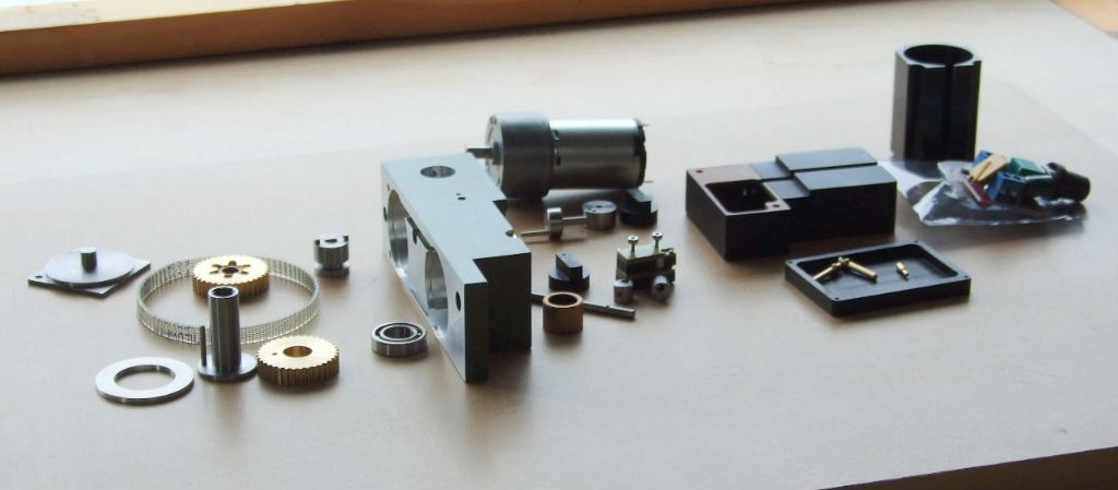
                                                      As is usual lately I have forgotten to add a photograph of the component parts of the feed attachment.

                                                      the revised table feed for proxxon mill.jpg

                                                      Regards

                                                      Gray,

                                                    Viewing 25 posts - 26 through 50 (of 61 total)
                                                    • Please log in to reply to this topic. Registering is free and easy using the links on the menu at the top of this page.

                                                    Advert

                                                    Latest Replies

                                                    Home Forums Manual machine tools Topics

                                                    Viewing 25 topics - 1 through 25 (of 25 total)
                                                    Viewing 25 topics - 1 through 25 (of 25 total)

                                                    View full reply list.

                                                    Advert

                                                    Newsletter Sign-up