Adaptation of the Proxxon Milling machine

Advert

Adaptation of the Proxxon Milling machine

Home Forums Manual machine tools Adaptation of the Proxxon Milling machine

Viewing 25 posts - 1 through 25 (of 57 total)
  • Author
    Posts
  • #14524
    Graham Meek
    Participant
      @grahammeek88282
      Advert
      #593872
      Graham Meek
      Participant
        @grahammeek88282

        Having already posted the above spindle modification I thought it might be as well to start a new thread as there are now quite a number of additions to the milling machine.

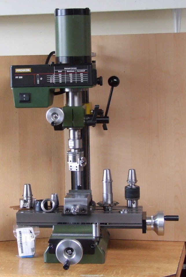
        fig proxxon tooling.jpg

        The above photograph shows the dedicated tooling to suit the ER 20 Spindle Nose. A new Spindle Nut which has a bayonet fitting allows the various tooling to be removed and added in an instant. Some of the early CNC's used this type of fitting but with ISO 30 & 40 tapers.

        The Spindle nut is so designed as to self eject the taper when removal is needed.

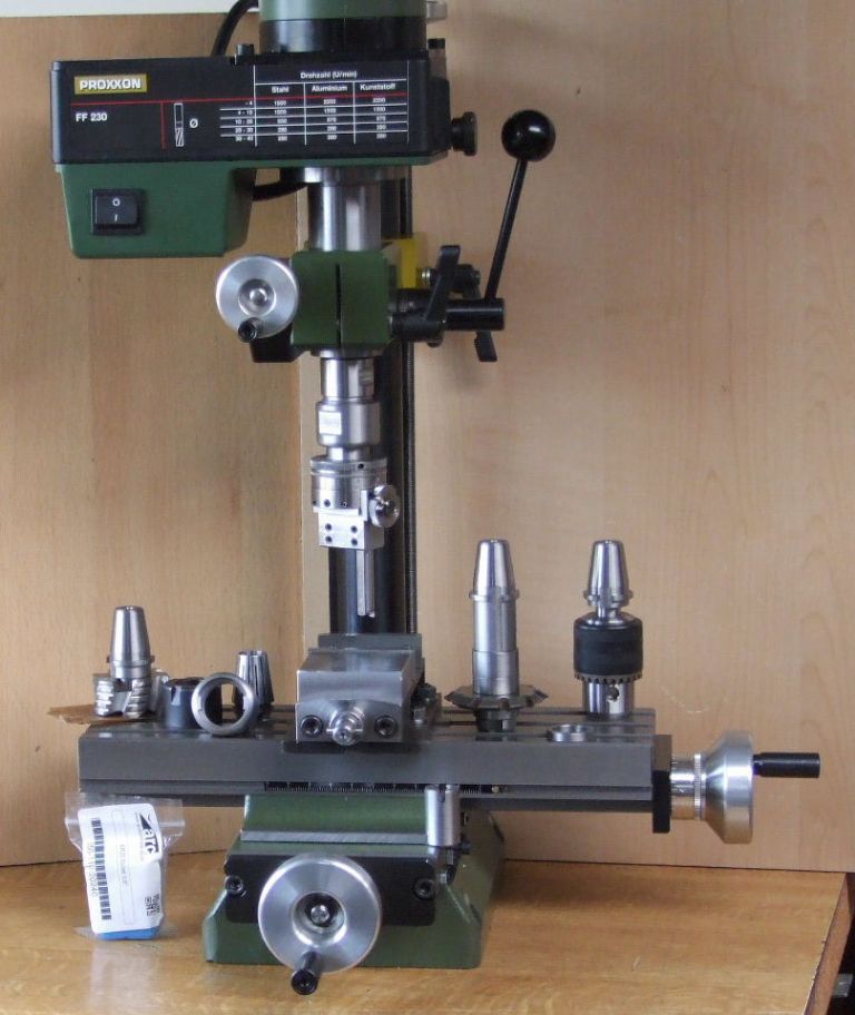
        fig proxxon.jpg

        The Bayonet design can be made out in the spare Spindle nut on the table in the above view.

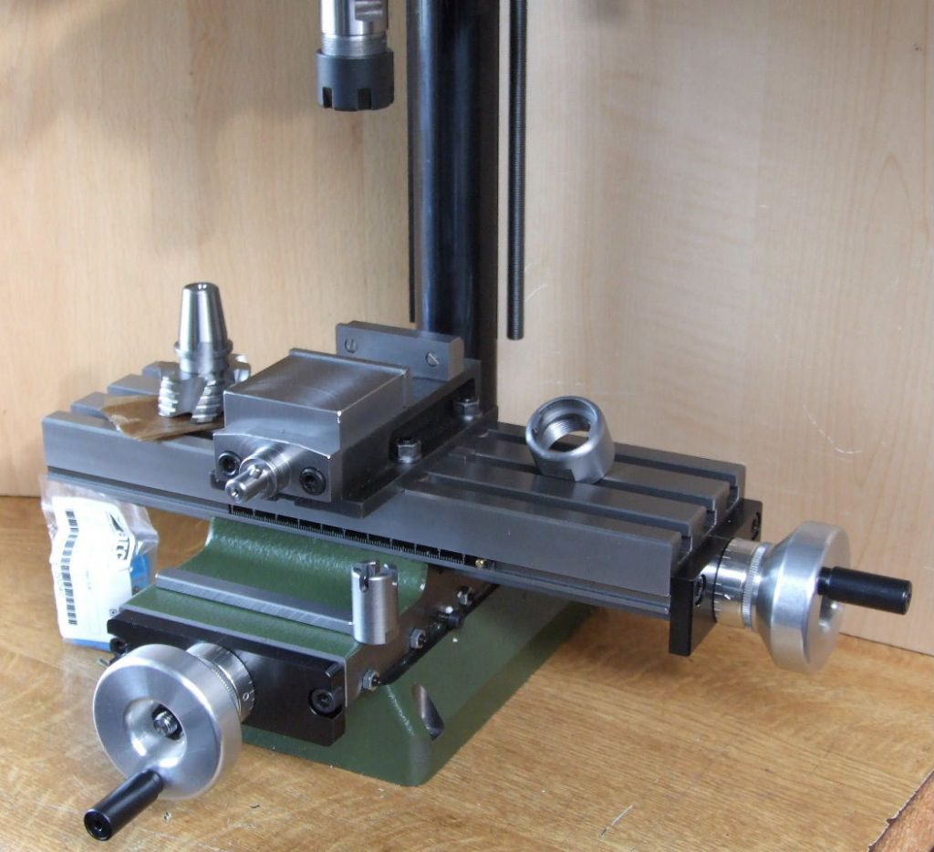
        proxxon machine vice.jpg

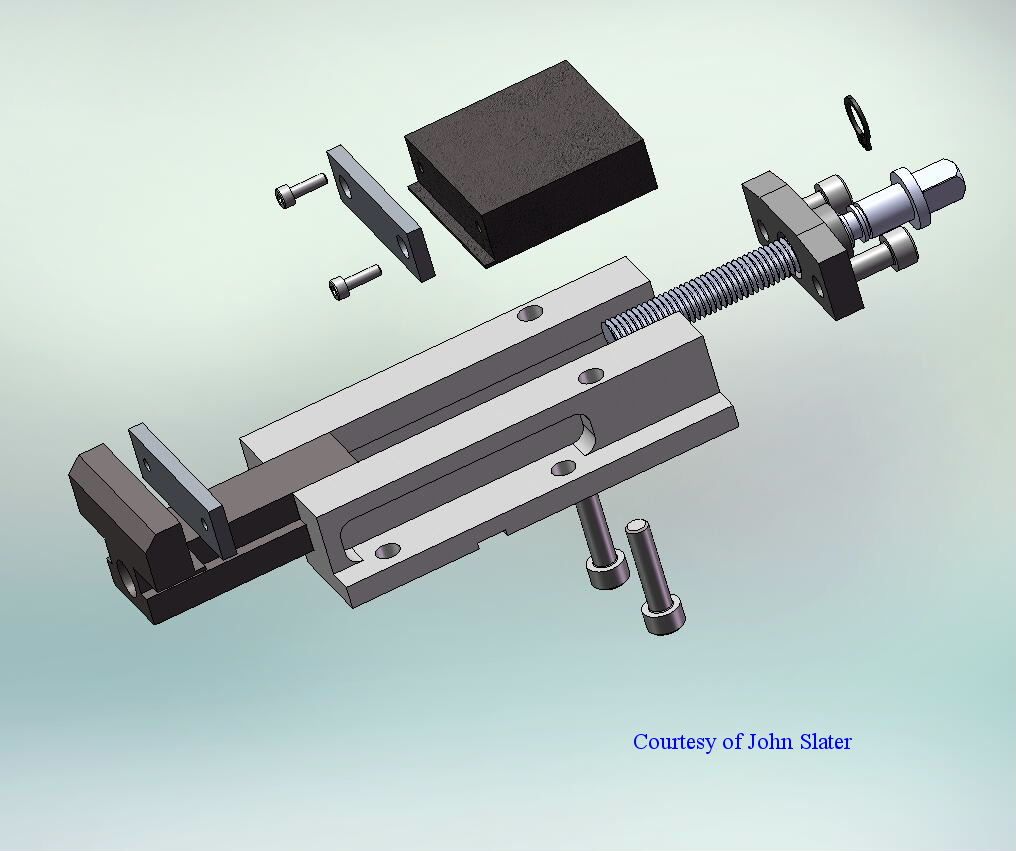
        I have also made a new vice for the machine, which is based on a Thiel design. John Slater was kind enough to do a 3D view of the design.

        fig vice.jpg

        There is a variable table feed under construction and I will be showing this at a later date.

        Regards

        Gray.

        Edited By Graham Meek on 10/04/2022 17:19:49

        #593875
        Michael Gilligan
        Participant
          @michaelgilligan61133

          Nice work, Gray yes

          MichaelG.

          #593937
          Graham Meek
          Participant
            @grahammeek88282

            Thank you Michael,

            Getting to this stage has been a bit of a struggle. Trying to keep several projects in the air at once is proving to be a tall order. As I am currently trying to finish a screwcutting clutch for my Emco Compact 5. Once this is finished I can complete my downsizing by retiring my FB2 and Maximat Super 11.

            Regards

            Gray,

            #607291
            Graham Meek
            Participant
              @grahammeek88282

              Well the FB2 and the Maximat Super 11 have now gone and the Screwcutting Clutch for the Compact 5 is now up and running. Along with a dedicated Retracting Topslide.

              Work has now transferred to getting the Proxxon Mill to where I would like it to be.

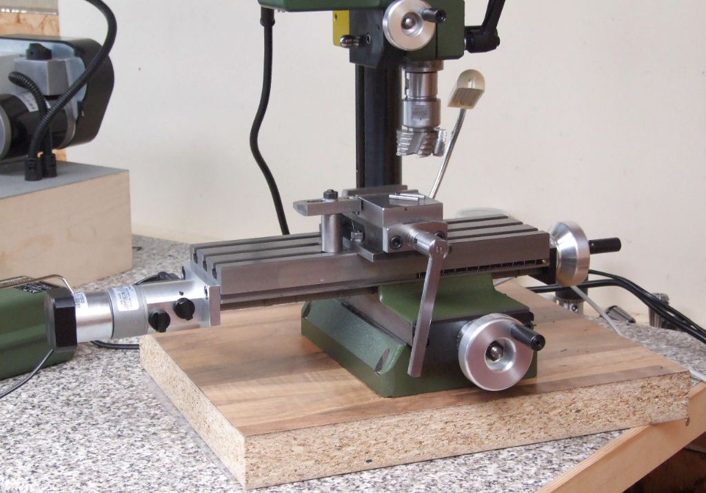
              proxxon table feed on milling machine.jpg

              The work on the Powered table feed is now complete as shown above. This has been used by jury rigging the wiring to produce the Delrin Connector block, come Micro-switch housing, as well as the End Cap for the motor. The finish produced by this small machine has impressed me.

              Please ignore my makeshift base for the milling machine. Work is in hand to make a base similar to my Unimat 3 base in the background.

              The Switch nearest the milling table engages the drive via a Dog Clutch. The Dog Clutch slides directly on the "D" shaped drive spindle on the reduction motor. As well as the drive shaft for the table feedscrew. Making the D-shaped hole was simplified thanks to an idea given to me by John Slater. More on that at a later date hopefully.

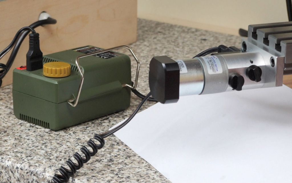
              proxxon table feed.jpg

              The second switch controls the direction of travel via a pair of micro-switches. Power currently comes form my Proxxon Micro-Mot power supply. This has a variable output and gives quite a good range of feeds with the 60 RPM motor. I may at a later date make a dedicated 12v power supply and control this via a PWM.

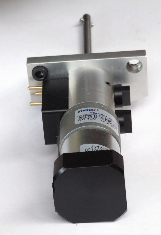
              the feed unit.jpg

              The Feed Unit was designed originally for John's X1 milling machine, another of our joint ventures. Thus it would be possible to adapt this design to fit most of the smaller milling machines. It would only require a different Endplate

              One possibility I am mulling over at the moment is a variable power feed for the Compact 5 Leadscrew using largely the same design.

              Regards

              Gray,

              #607297
              Jamie Wood
              Participant
                @jamiewood67138

                Hi Gray,

                The feed unit looks great, I don't think I've seen one made for such a small machine before.

                It's definitely inspiration for me to build a proper one for my Compact 5 mill table. Upto now I've been driving it with a small battery screwdriver.

                In the last photo does the cross pin slide into a slot on the end of the leadscrew to drive it?

                Thanks,

                Jamie

                #607308
                duncan webster 1
                Participant
                  @duncanwebster1

                  You don't need a clutch between stepper motor and lead screw, just wind the motor round by hand when manual feeding. The controller needs to be de-energised of course

                  #607324
                  Steve F
                  Participant
                    @stevef

                    Hello Gray

                    I'm very interested in your modifications to the mill. I have one sitting in the box. I feel inspired to set it up and have a go. I saw a photo of the spindle change to ER but couldn't find the details anywhere. Was there a diagram somewhere ?

                    I would also like to see more details of the power feed / clutch arrangement. I had a similar arrangement on my old mill but your clutch housing looks good.

                    If you ever consider using stepper take some care. You will still get cogging from a unpowered stepper and the stepper will generate a back emf into the controller that could destroy the drivers.

                    regards

                    Steve

                    #607344
                    duncan webster 1
                    Participant
                      @duncanwebster1
                      Posted by Steve F on 25/07/2022 15:55:21:

                      ……..You will still get cogging from a unpowered stepper and the stepper will generate a back emf into the controller that could destroy the drivers.

                      regards

                      Steve

                      It hasn't destroyed mine in several years of use.

                      #607345
                      bernard towers
                      Participant
                        @bernardtowers37738

                        Graham, Any chance of a sketch of the bayonet fitting and nut as thatnsounds a good mod for any of the ER collet chucks.

                        #607348
                        Graham Meek
                        Participant
                          @grahammeek88282

                          Hi Jamie,

                          The Compact 5 Mill was my first choice when replacing the FB2, but as you know these are like Hen's Teeth.

                          You are right in your assumption about the cross pin driving the feed screw. Holding the feedscrew in a collet and reaming a hole was the easiest option. Using a Woodruff cutter it is a simple matter to put in the slot, which does not need to be a good fit on the drive pin. I used a 3mm pin with an 1/8" or 3.2mm wide slot. This avoids any slot symmetry problems.

                          Hi Steve,

                          I am hoping in due course to write an article on the feed unit. Maybe I can get John to do a 3D of the design in the meanwhile.

                          Hi Bernard,

                          As with my answer to Steve, it is my intention to write up this modification later on and if Neil is agreeable I submit the article.

                          Generally,

                          As regards Stepper motors this is a bit too complicated for me, and I do recall on some machines fitted with stepper motors I have used, that Cogging is an issue especially when trying to make small adjustments.

                          My method is dead simple, this gives me no such problems and the only cost is the 12v 60 RPM gearbox motor, the power supply I already had.

                          Regards

                          Gray,

                          Edited By Graham Meek on 25/07/2022 19:33:10

                          #607362
                          bernard towers
                          Participant
                            @bernardtowers37738

                            Look forward to then article Graham I hope Neil doesn't take too long to put it in print.HINT HINT

                            #607373
                            Steve F
                            Participant
                              @stevef

                              Hello

                              Thanks for the reply. I'll keeps my eyes open

                              regards

                              Steve

                              #607405
                              Graham Meek
                              Participant
                                @grahammeek88282

                                Thank you both for being so understanding. It may be a while before it gets into print though.

                                Regards

                                Gray,

                                #608407
                                Graham Meek
                                Participant
                                  @grahammeek88282

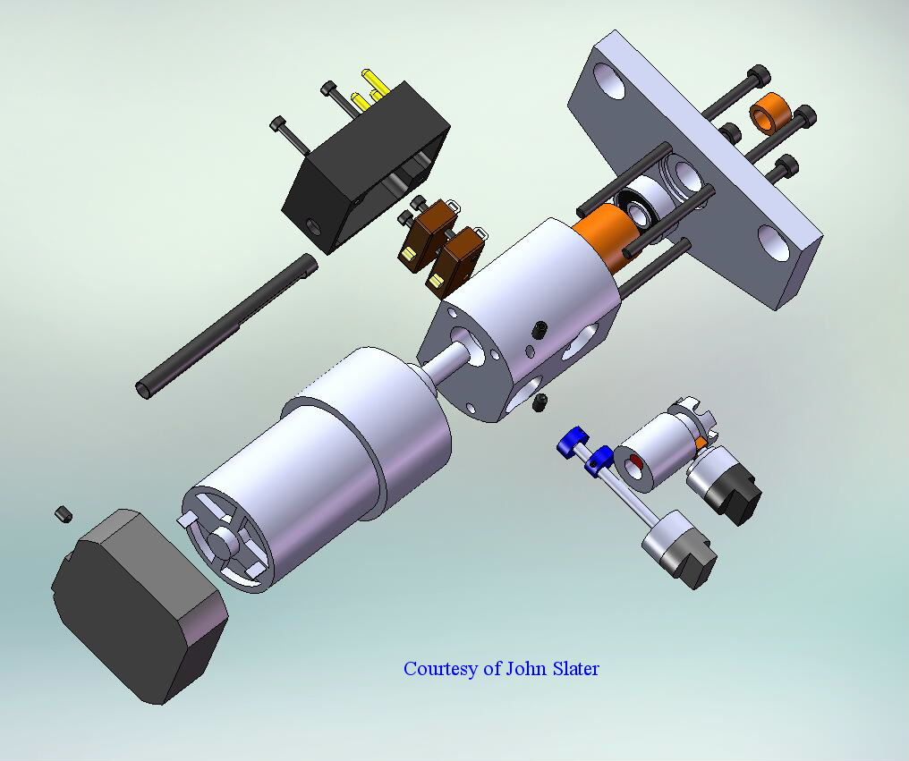
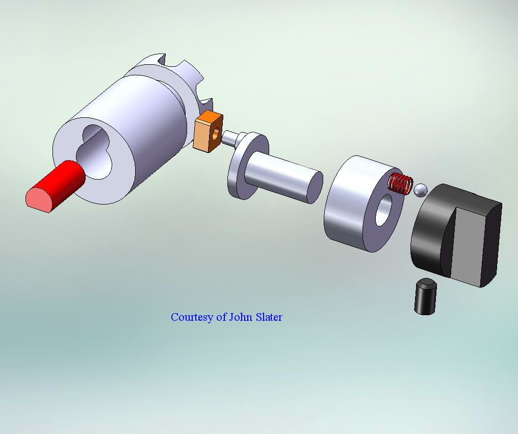
                                  John Slater has once again worked his magic on my drawings and made things hopefully a lot clearer as regards what is going on, on the inside.proxxon table feed unit assy.jpg

                                  Two simple eccentric cams work the two micro switches to give left and right feed directions.

                                  dog clutch details.jpg

                                  The Dog clutch is a little more complicated but both sets of Selector Knobs have a spring loaded ball to ensure the knobs stay engaged, or disengaged, during any vibration that might arise due to intermittent cutting action.

                                  Regards

                                  Gray,

                                  Edited By Graham Meek on 04/08/2022 17:28:52

                                  #617050
                                  Graham Meek
                                  Participant
                                    @grahammeek88282

                                    It has been a while since I posted anything on the Milling machine mods so I thought I had better give you an update.

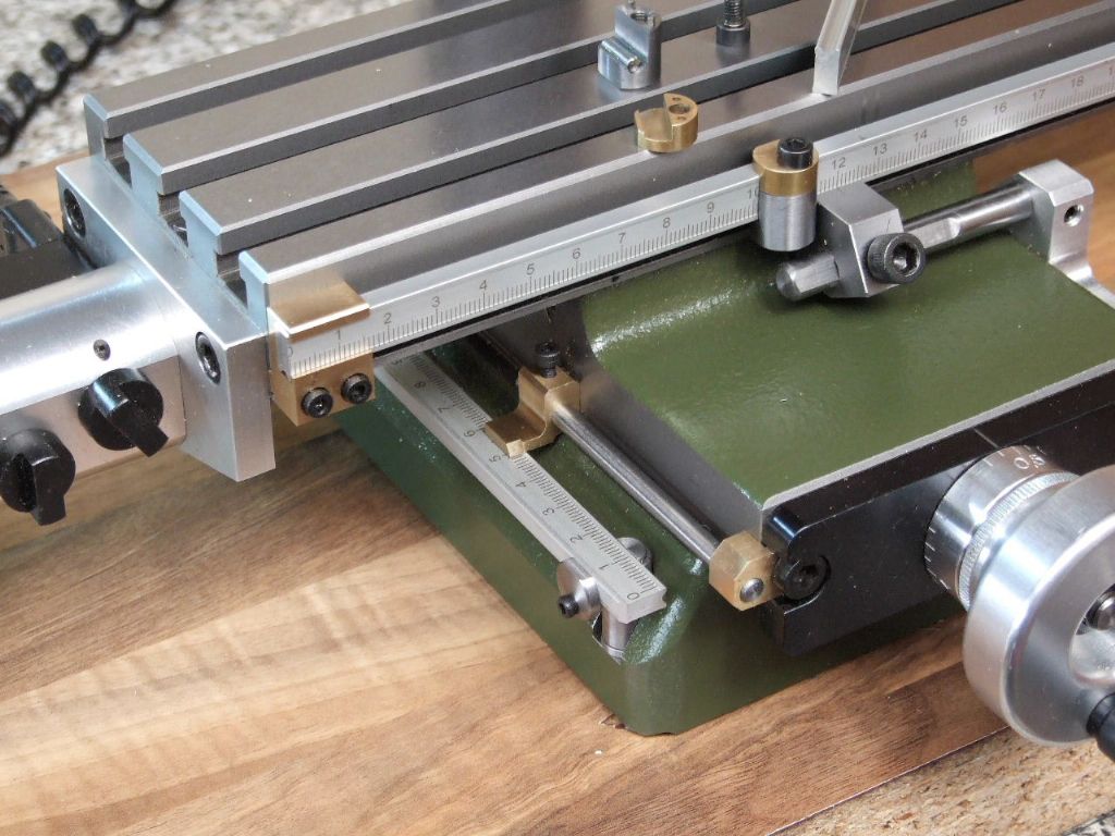
                                    x and y scales fitted.jpg

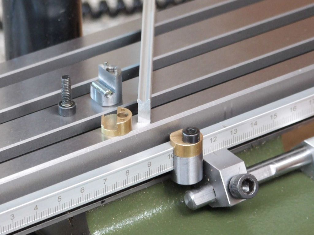
                                    This shows the fitment of some scales taken from a pair of cheap Aluminium Vernier Depth gauges. I has tried to get some 6 mm wide metric rules but these proved elusive at the time. In the end it worked out for the best as the X-axis Table Stops work better than I expected.

                                    y-axis scale.jpg

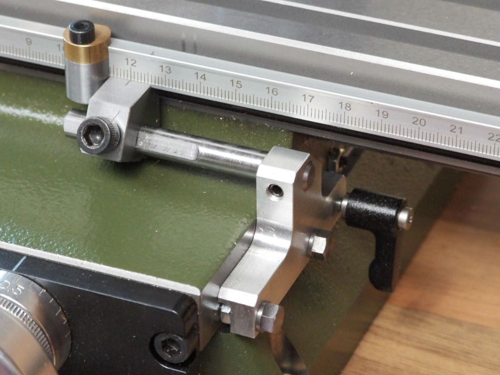
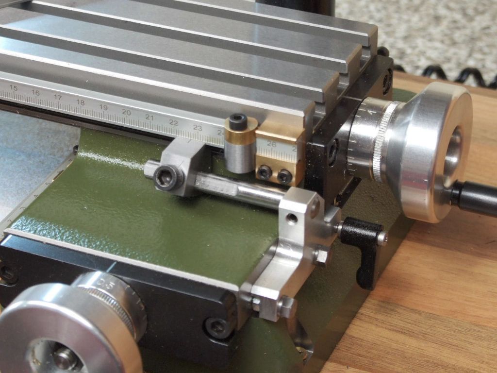
                                    I have tried throughout to fit these items without drilling and tapping the machine. The Y-axis utilises the mounting hold down bolt holes to hold the scale and one of the feedscrew plate retaining bolts to hold the pointer.

                                    x-axis attachment.jpg

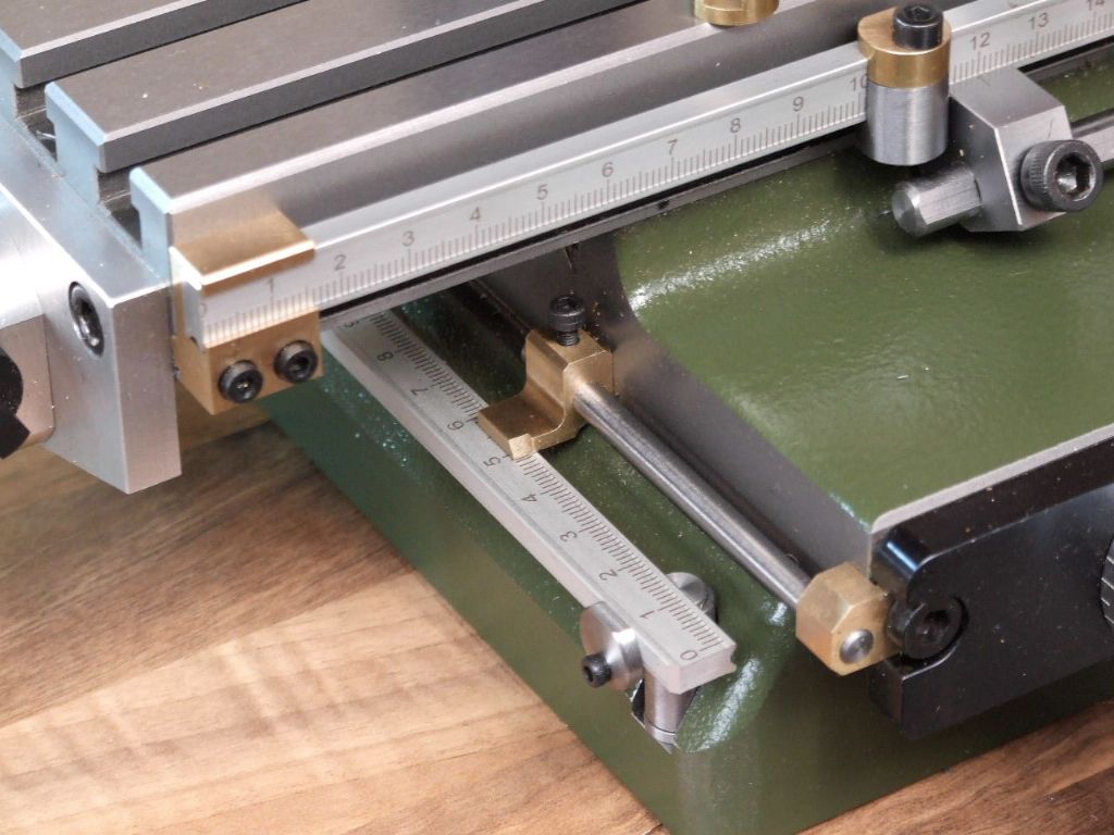
                                    The X-axis is piggy-backed onto the Gib adjusting screws. One Gib locknut can be seen in a clearance cut-out at the front of the aluminium bracket. The scale itself is held by two M3 cap head screws and these had to used tapped holes in the bottom of the old scale dovetail slot on the front of the table.

                                    x-axis table stops.jpg

                                    The scales from the vernier have an inverted Vee in one face. The table stops utilise this Vee to locate a 3 mm dowel which is held in the stop with Loctite. A hook like up-stand on the brass clamp stops retains the stop during adjustment.

                                    checking clearances.jpg

                                    This last view shows the brass block which holds the scale. A Tenon on the back of the block locates in the previously mentioned redundant scale slot.

                                    It may take a little tweaking to get the set-up just right but that will come with time and usage. I have already noticed I am quicker when doing a co-ordinated hole pattern.

                                    Regards

                                    Gray,

                                    #617184
                                    Graham Meek
                                    Participant
                                      @grahammeek88282

                                      A lot of the modifications are coming to an end, however there are one or two items that need rectifying. When I set this mill up for the first time. I decided to do some alignment checks. Tramming the head was a must and here I had a shock.

                                      There was nearly 0.2 mm run across the table when rotating the clock held in the spindle over the width of the table. This was not something I was expecting from Germany. Some of the run was attributed to the Column not being vertical.

                                      The column has a turned down portion on the end to fit in a hole in the base of the machine. The problem was there was 0.03 mm taper on this turned down portion. Smaller at the bottom of the column. Because two 8 mm grubscrews to the rear of the column are used to clamp the column in place. The bottom M8 screw was pushing the column over due to the taper on the spigot. This made it lean away from the operator.

                                      To overcome this I inserted a tapered steel plug inside the tubular column. This was drawn into place with an M8 piece of studding and a roller thrust race under the nut. This rectified the taper and also made the clamping area solid. The column now sat dead vertical as I would expect. Why the column is turned down 1 mm smaller escapes me. It is an un-necessary operation, why not make the hole 1 mm bigger.

                                      However the run still existed but luckily it was much less, but still more than I was willing to live with. Enter the milling head from a spare second-hand milling attachment. Clocking this head showed very little error. Thus there was a duff part somewhere.

                                      Thus it now has become the time to sort this problem out.

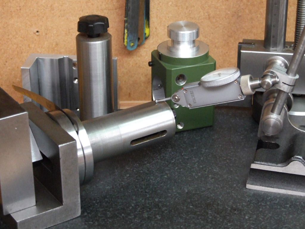
                                      checking first side.jpg

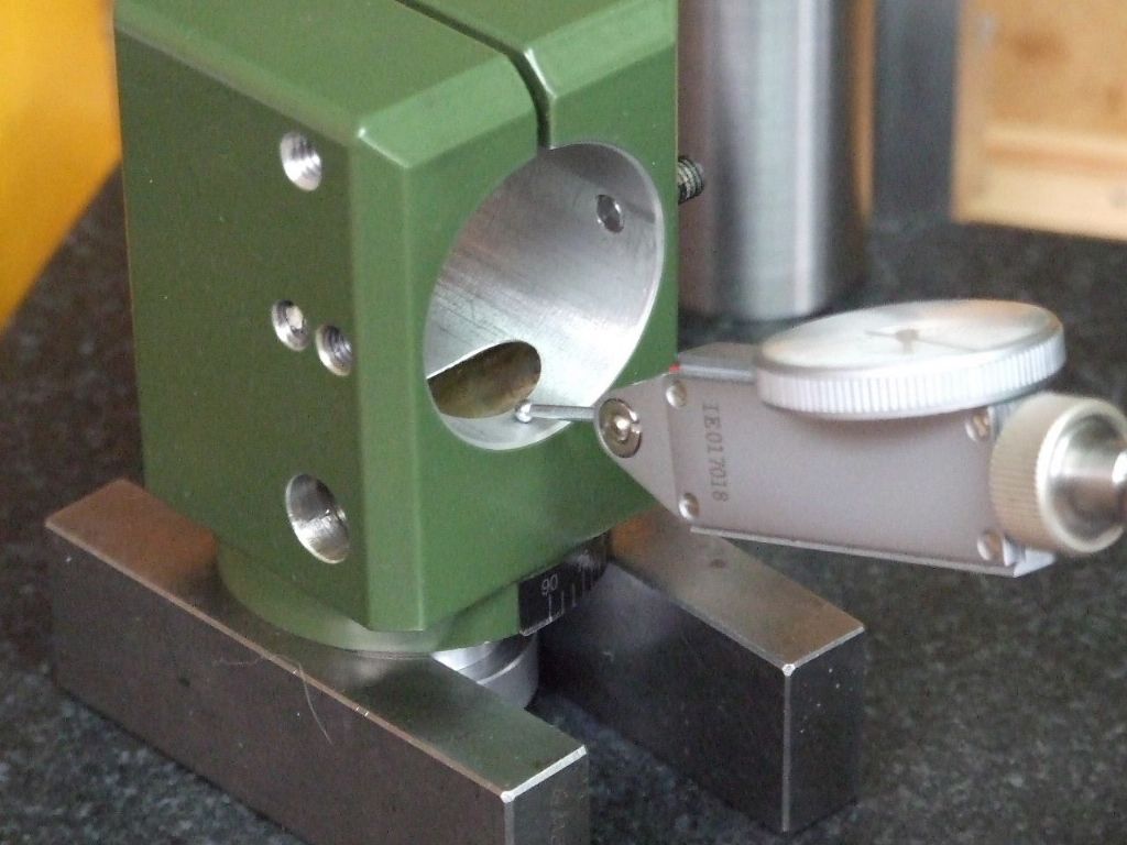
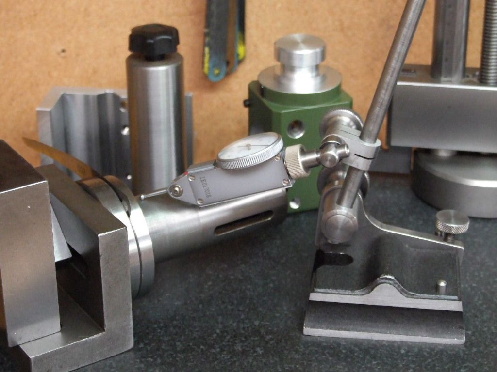
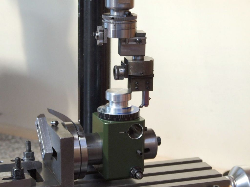
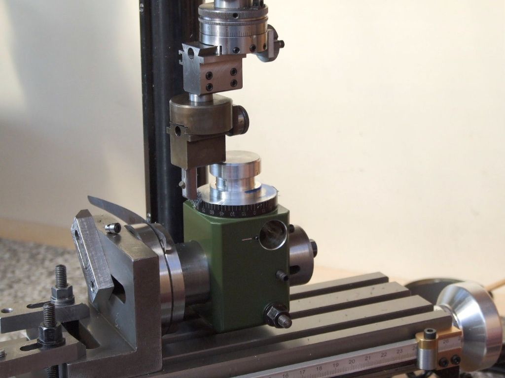
                                      This is the setup used to track down the error, above I am checking the first side before rotating the Quill housing on the parallels.

                                      checking second side.jpg

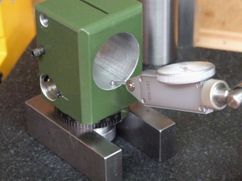
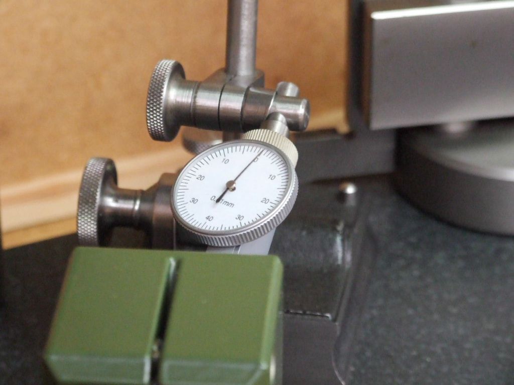
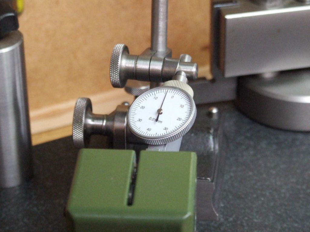
                                      These next two photographs show the the readings at these points.

                                      reading first side.jpg

                                      reading second side.jpg

                                      Whilst 0.04 mm might not seem a lot this is only half of the error across the width of the table. (The Quill Housing is half the width of the milling table).

                                      Now I knew where the error was time to set about fixing it.

                                      More on that later,

                                      Regards

                                      Gray,

                                      #617298
                                      Graham Meek
                                      Participant
                                        @grahammeek88282

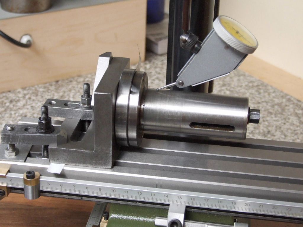
                                        To get the salvage scheme under way I decided to set the spare Quill up on an angleplate.clocking spare quill.jpg

                                        To get a Zero-Zero reading at either end of the quill a 0.05 mm feeler blade was inserted at the top of the Quill.

                                        clocking opposite end of quill.jpg

                                        Once the readings were the same the assembly was transferred to the milling machine table.

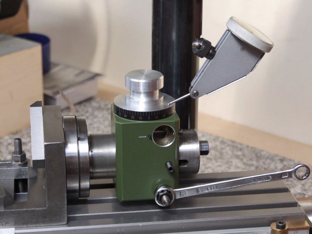
                                        setting up on the milling machine.jpg

                                        While the reading on the surface plate was zero at both ends. When the assembly was clamped to the table there was a small error. Hence the piece of Cigarette Paper towards the rear of the angle plate.

                                        setting face parallel to y-axis.jpg

                                        The offending part was then mounted on the quill and clocked true to the Y-axis and locked.

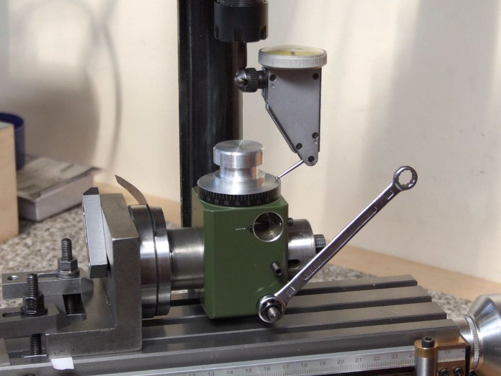
                                        verifying direction of run-out.jpg

                                        The next check was to see if the initial run-out was in the same direction as it was on the surface plate, which it was. With the stylus of the clock at such an angle, the reading on the clock cannot be trusted as regards a measurement. The clock is merely being used to indicate a run-out.

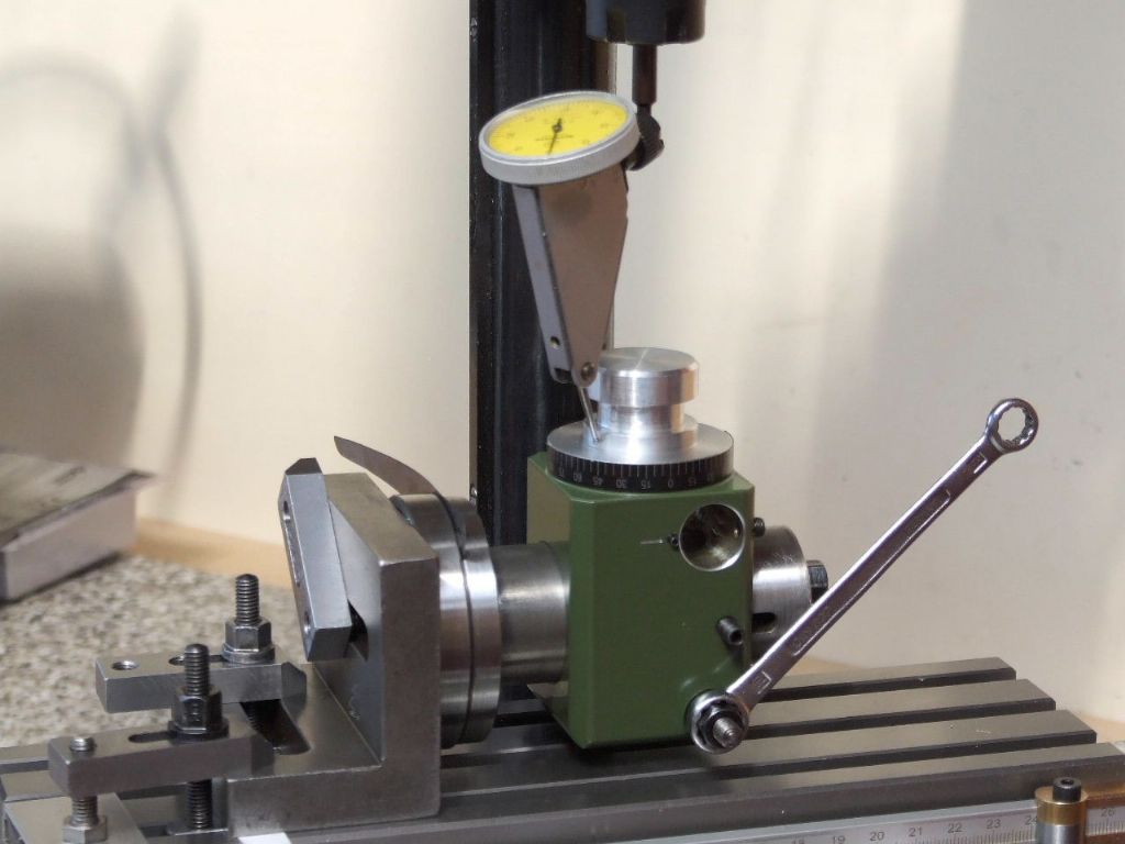
                                        clocking for concentricity with spindle.jpg

                                        The last job for the clock was to bring the spigot onto the same centreline as the milling spindle.

                                        Another portion of the salvage shortly,

                                        Regards

                                        Gray,

                                        #617299
                                        Michael Gilligan
                                        Participant
                                          @michaelgilligan61133

                                          Exemplary work [and ‘work-flow if that’s an acceptable term] Gray

                                          Thanks for the ‘MasterClass’ yes

                                          MichaelG.

                                          #617392
                                          Jamie Wood
                                          Participant
                                            @jamiewood67138

                                            Very interesting work Gray.

                                            I have recently bought a Proxxon column assembly from a PF400 that I plan to use to improve the rigidity/usability of my C5 mill somewhat. The new column, at 45mm is 10mm thicker than the Emco and has the benefit of keyed clamping block and Z leadscrew. After reading this I will definitely be checking the accuracy of my parts before I start making a new mounting clamp/base.

                                            Your new X/Y scales look great as well, the stops are a nice addition. Do you think you might ever try to fit some digital ones on there? I just about managed to squeeze some onto my C5 table, although with the new column they may need some adjustment

                                            Jamie

                                            #617398
                                            Graham Meek
                                            Participant
                                              @grahammeek88282

                                              Hi Michael,

                                              Thanks for the kind words, in an ideal world the part should have gone back.

                                              Unfortunately post Brexit things from the continent now take months instead of days. I had waited 3 months for the milling table base to go with the vertical attachment I already had. In the end I purchased a complete machine.

                                              Thus getting a part replaced under warranty would just take too long in my book. There is also the chance that the replacement will be no better.

                                              The actual amount of material removed was miniscule to correct the part, but I am not impressed with my set-up. It was hoped to machine the offending face of the component using my homemade boring & facing head. While the head had sufficient travel to do the job in hand, the head would not extend far enough.

                                              not the best set-up.jpg

                                              As the Proxxon is now my only working source of milling machine, (The Unimat 3 is still waiting for attachments), it was either strip the set-up down and make an extension holder for the boring bar, something that is now underway. Or adapt something to extend the range of the existing boring head.

                                              I have had for some time a small manual boring head. This has a detachable 12 mm shank, so a new 8mm one was made and the additional boring head offered up. At the bottom speed of 280 RPM I was expecting the machine to throw a wobbly, but it did not show any signs of complaint.

                                              but it worked.jpg

                                              Whilst the set-up had more overhang than I would like it performed the job in hand to my satisfaction and produced an excellent finish. The swarf can be seen on the boring bar.

                                              Re-assembling the milling machine it would be nice to say it was perfect upon re-checking. I had decided I would accept a total run-out of 0.05 mm. Luckily it was less than this at max error of 0.01 mm, thus a mornings work including the photo session was well worth the effort.

                                              After all I had a result the same day. Despite the poor engineering of the machine it is still a good design and works well given its diminutive size. The Proxxon School Report would read "could have done better"

                                              Regards

                                              Gray,

                                              All the right letters but not in the right order!

                                              Edited By Graham Meek on 15/10/2022 13:04:29

                                              #617408
                                              Graham Meek
                                              Participant
                                                @grahammeek88282
                                                Posted by Jamie Wood on 15/10/2022 12:35:34:

                                                Very interesting work Gray.

                                                I have recently bought a Proxxon column assembly from a PF400 that I plan to use to improve the rigidity/usability of my C5 mill somewhat. The new column, at 45mm is 10mm thicker than the Emco and has the benefit of keyed clamping block and Z leadscrew. After reading this I will definitely be checking the accuracy of my parts before I start making a new mounting clamp/base.

                                                Your new X/Y scales look great as well, the stops are a nice addition. Do you think you might ever try to fit some digital ones on there? I just about managed to squeeze some onto my C5 table, although with the new column they may need some adjustment

                                                Jamie

                                                Hello Jamie,

                                                Glad you like my old school scales.

                                                I had hoped to purchase a good FF400 mill when I was looking around for a replacement for my FB2. Unfortunately these are like Hen's teeth. It would have matched the C5 capacity better.

                                                I did consider at the outset fitting digital scales, especially as my memory is not so good these days. Upon checking the clearances under the table feed unit this was not going to be that easy. Plus the reading heads on the scales looked totally out of proportion on this machine. This coupled with my planned usage these days I could no justify the expense. I would still have needed to put some form of bar on the machine to carry the table stops.

                                                What are you intending to do with the C5 Milling head?

                                                Regards

                                                Gray,

                                                #618103
                                                Jamie Wood
                                                Participant
                                                  @jamiewood67138

                                                  Hi Gray,

                                                  That's fair enough, it was a tight squeeze getting the digital scales on the C5 table, in fact I didn't account for one of the reader box parts just clipping the column mount, and thus lost a bit of Y travel, which is part of the reason for this column replacement. I've actually been thinking of wiring them up to a tablet using touchDRO to get some of the extra benefits of 'proper' DROs.

                                                  Sorry to get your hopes up, but I only have the Proxxon column and column clamp, so I'll still be using the C5 head but adapted to fit this. It may end up looking a bit clunky, but as long as it improves the milling capabilities!

                                                  Maybe I'll have to start my own thread on here to document in case anyone else is interested.

                                                  Thanks,

                                                  Jamie

                                                  #618131
                                                  Graham Meek
                                                  Participant
                                                    @grahammeek88282

                                                    Hi Jamie,

                                                    Sorry I misunderstood your post. I thought you had the Proxxon head as well. This has a better speed range than the C5 and that range is also better than the milling head on my mill. The fact you can mount cutters directly in the spindle is a big bonus with these machines.

                                                    That is not such a bad idea about the thread showing your mods.

                                                    Regards

                                                    Gray,

                                                    #625670
                                                    Dick H
                                                    Participant
                                                      @dickh

                                                      I have a Proxxon FF230 mini (nano?) mill, Can someone please tell me how to remove the stepped pulley at the top of the spindle? There is a very small grub screw to be removed and then I assumed the pulley should be able to be pulled off. Am I missing something? Is it screwed on or has someone used a locking compound on the shaft? I don´t want to use too much umph on it.

                                                      Dick.

                                                    Viewing 25 posts - 1 through 25 (of 57 total)
                                                    • Please log in to reply to this topic. Registering is free and easy using the links on the menu at the top of this page.

                                                    Advert

                                                    Latest Replies

                                                    Home Forums Manual machine tools Topics

                                                    Viewing 25 topics - 1 through 25 (of 25 total)
                                                    Viewing 25 topics - 1 through 25 (of 25 total)

                                                    View full reply list.

                                                    Advert