Referring to Andrew Tinsley’s thread …
Why ACME threads on leadscrews?
**LINK**
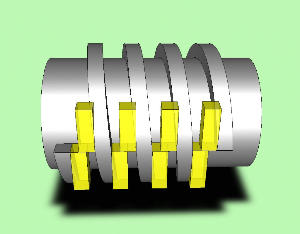
At the time, a CAD image seemed an appropriate method of displaying how the helix angle presents an undercut. It also offered another explanation why lathe leadscrews have ACME profiles.
To digress slightly, helix undercutting can be an issue with moulded external threads, and often influences the choice of thread profile. The angle of the pressure face of a buttress thread is one such instance.
Unfortunately, try as I might, I failed to discover how to manipulate the solids, i.e. subtract the yellow blocks from the helix. I left it looking like this …

That was back in 2017.
The other day a friend of mine mentioned that he had made some cast iron half-nuts to fit a new 12x2mm ACME leadscrew for the lathe he was refurbishing. The nut halves were a tight fit on the leadscrew so he decided to lap them using a leadscrew offcut. After lapping the thread of the half-nuts he discovered ‘… the fit was too good and was making it difficult to engage and almost impossible to disconnect under load.’
It was time for me to fire up the seventeen year old CAD package and search again for a way of generating a solid that I could manipulate. After squinting at and dabbing icons for a while, I suddenly spotted one I’ve used many times.
Create Swept Solids.
This was one of several dropdown windows exposing blocks of icons. There, amongst the block of six was …
‘Create a solid by Sweeping a Profile along a Helix’
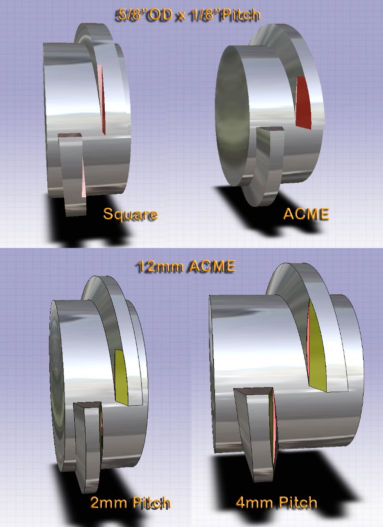
We were in business, and soon I had four images showing the extent of interference, bearing in mind that I was using size for size, i.e. no clearances and no radii etc.

Travelling perpendicular to the thread axis, you can see how the undercuts interfere.
This issue has clearly been known since the late 1800's, yet I can't find a link. What do you people think?
Sam
Footnote: Usually, half nuts are less than half. Is that intentional?
 Michael Gilligan.


