A Well-Tempered Hybrid Pendulum Clock Project

Advert

A Well-Tempered Hybrid Pendulum Clock Project

Home Forums Clocks and Scientific Instruments A Well-Tempered Hybrid Pendulum Clock Project

Viewing 25 posts - 51 through 75 (of 96 total)
  • Author
    Posts
  • #658223
    S K
    Participant
      @sk20060

      All materials are unstable. It's a law of the universe. (People too, some more than others – hehe.)

      Invar has been particularly well studied for this, given its use in advanced scientific instruments. But I don't believe the "sudden", "single day" instability claims or other anecdotal reports that are much more likely due to measurement errors. Creep over time under load I can believe, though, but the same is true for all metals. For example, the Young's modulus (not quite the value of interest, but it's something) of Invar is about twice that of aluminum, about the same as cast iron, but lower than typical stainless steel.

      I'll take Invar over other metals with 10-20x the thermal instability, and over the quite unexplored instability of carbon fiber. (Indeed, "carbon fiber" is not one thing, there are hundreds of manufacturers using extremely-diverse manufacturing methods, weaving and extruding strategies, binding agents and finishing techniques.)

      I'll also keep my "gorgeous" brass bob, with its ~20% higher density than steel or iron (but I'll remain jealous of John's tungsten bob!).

      Invar has been successfully used in some of the most accurate clocks and other instruments ever made. But if I ever launch into making a superior pendulum, I'll hunt down something like a 2" diameter fused silica rod, and use that alone – no bob – in vacuum.


      Edited By S K on 27/08/2023 17:09:03

      Advert
      #658244
      S K
      Participant
        @sk20060

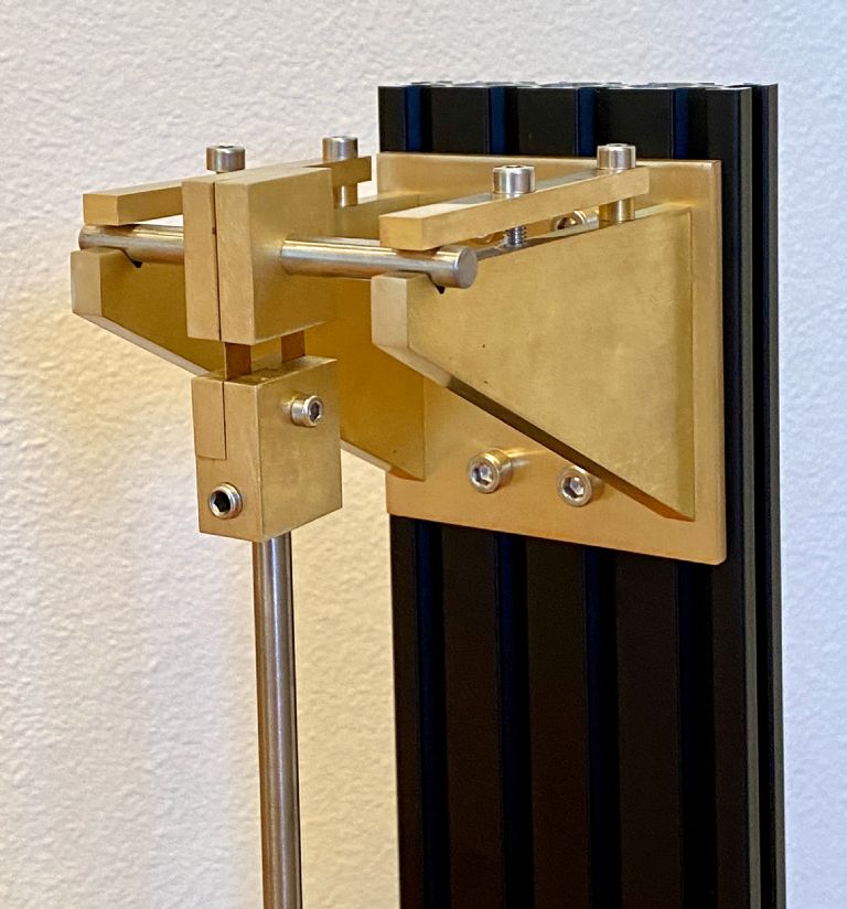
        I realized that I needed a test stand, as it would be too difficult adding electronics and testing the pendulum while mounted to the wall it's intended for, so I printed a pair of brackets and mounted the whole pendulum to a base:

        img_4989.jpeg

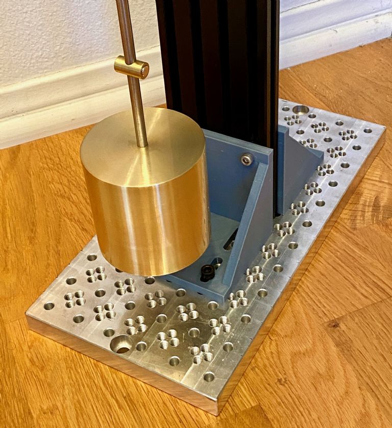
        It's more than sturdy enough for functionality tests, but not rigid enough for highly detailed measurements. It doesn't look like it, but the bob easily clears the lower bracket:

        img_4988.jpeg

        I still have to add a flag, which I'll probably do in brass to match the rest of the pendulum. The electronics such as the opto sensor and the drive coil(s) will probably be mounted on 3D printed supports.

        It's starting to look real! 🙂

        #658279
        SillyOldDuffer
        Moderator
          @sillyoldduffer

          I like it very much, but what's with all those holes in the brass plate?

          Very pretty, but having plenty of mass at the bottom is a good thing. On second thoughts, it makes sense if the column is bolted to the wall, with the base plate hanging off it to support the optics.

          An observation rather than criticism – fascinating stuff.

          By the by, it's worth chamfering the bob top and bottom to reduce turbulence. I guess a large round fillet would be best, but a small flat chamfer would do good.

          Dave

          #658290
          John Haine
          Participant
            @johnhaine32865

            I think that must be an aluminium or steel tooling plate?

            #658308
            S K
            Participant
              @sk20060

              Yes, it's an aluminum tooling plate that I've repurposed as a temporary base. I want to be able to set it beside my computer while I'm installing and debugging the electronics, etc. Later, I'll wall mount it without the base.

              I wish I could have chamfered it! Unfortunately, my puny 3" chuck can only hold the bob by tiny fingernails. There isn't enough grip. Or rather, I could do one end of it, but then I wouldn't be able to hold it at all when flipped around. The bob was the biggest and heaviest thing by far I've put in my toy lathe. It was on the ragged edge of its safe limit, and I spun it very slowly lest those tiny fingernails let go!

              #658320
              Martin Kyte
              Participant
                @martinkyte99762

                Come on SK it’s got a hole down the middle. Can’t be beyond the wit of man to mount it on an arbor to machine the chamfers?

                regards Martin

                #658325
                S K
                Participant
                  @sk20060

                  Haha, the bob was too big for my tail-stock, even, so that's out. Work holding anything larger than a postage stamp is my biggest problem. I need to blow a bunch of money on some real equipment!

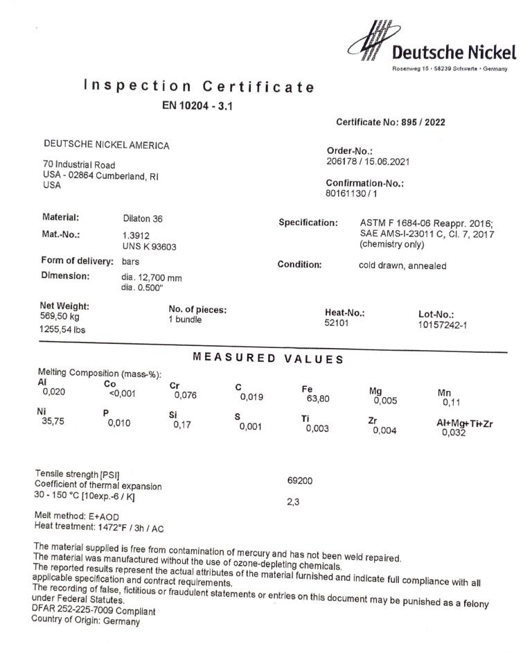
                  An interesting update: I found more information on the Invar rod. "Invar" is a trade-marked name, so this is "Dilaton 36," made in the U.S. It's "cold drawn, annealed." I recall that annealing was discussed as a step in preparing Invar for good stability, so that's fine.

                  The coefficient of thermal expansion is quoted as 2.3. That's larger than the canonical number, but at least I have it and I can adapt the pendulum to it. I've bought a short rod of the same material that I may use inside the bob, so that the main compensator can be completely outside it for lower temperature lag. If I feel ambitious enough, I also want to make a new hinge out of it, as the brass in my current hinge is already large enough to affect temperature stability.

                  img_4995.jpeg


                  Edited By S K on 28/08/2023 19:30:14

                  #658559
                  S K
                  Participant
                    @sk20060

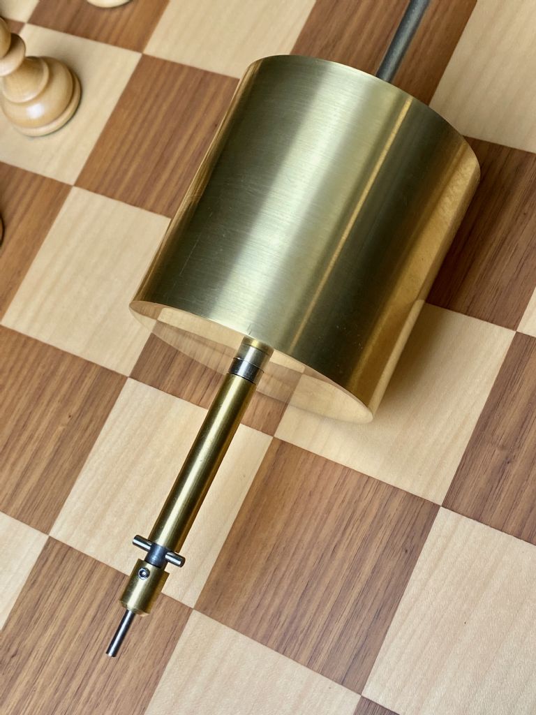
                    I redid the temperature compensation based on the above data, and also to include an Invar isolator.

                    The Invar sleeve resides inside the bob from the bottom, supporting the bob at its 50% point. Its goal is to reduce temperature lag due to the large thermal mass of the bob by isolating the bob from the brass compensation. The Invar sleeve extends below the bob by about 0.15" to provide a small amount of additional isolation outside the bob. The main brass compensator sits below the Invar sleeve.

                    Will it work? It will still be off by some random amount. Hopefully it won't make things worse! If I measure a clear temperature dependence, I might alter the brass compensator to include a small (e.g. 3 piece) binary weighted stack for easier adjustment.

                    I also made a small pointer, positioned at the bottom of the rod, to trigger the opto-interrupter.

                    I'm almost ready to add electronics.

                    img_4997.jpeg


                    Edited By S K on 30/08/2023 21:07:42

                    #659106
                    S K
                    Participant
                      @sk20060

                      Progress on electronics:

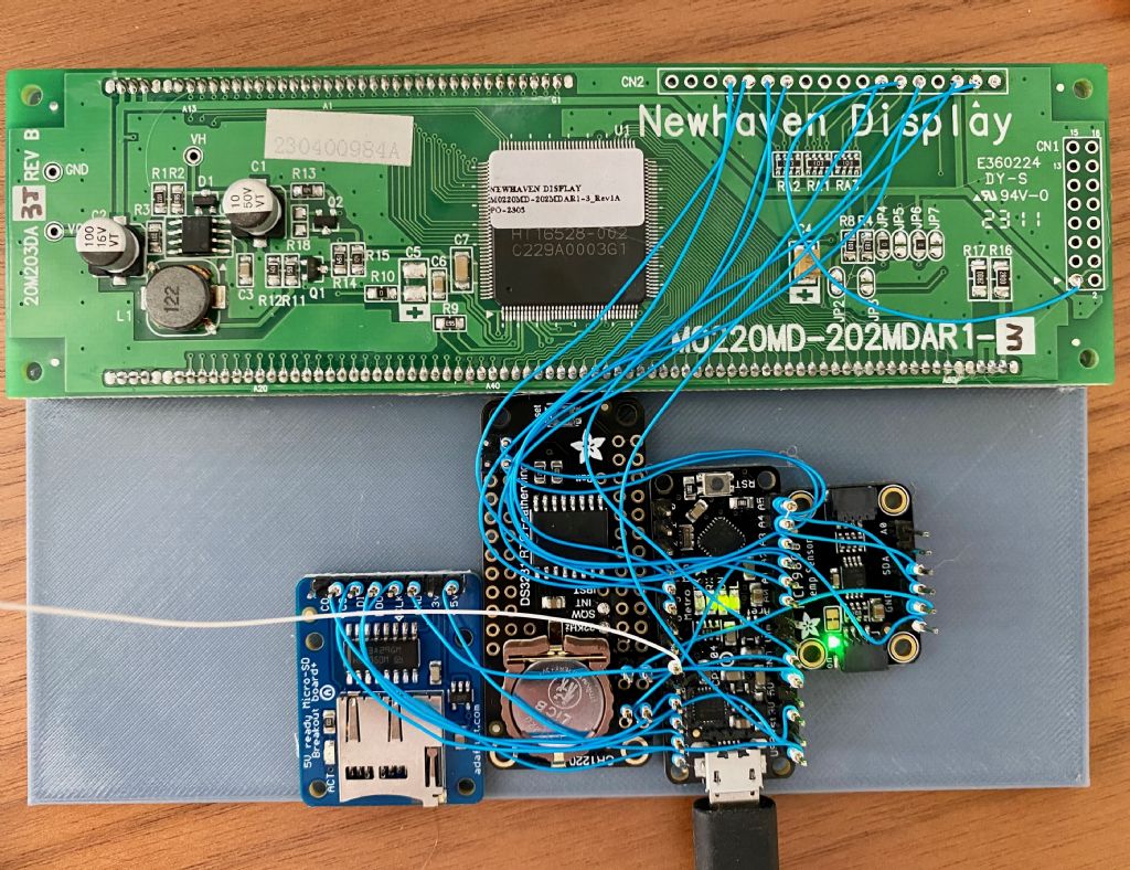
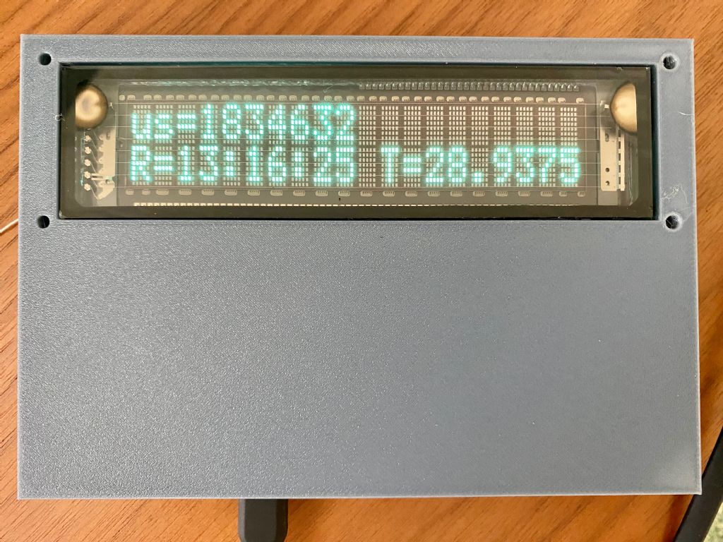
                      I put together a prototype system consisting of a mini Arduino, a DS3231 real time clock, a MCP9808 temperature sensor, an SD card slot, and a vacuum florescent display unit. For now, the items are lightly tacked on using hot glue, and I used the "wire-wrap" technique for easy changes. Later I'll install everything more permanently.

                      • The popular DS3231 RTC is temperature compensated and is good for +/-2 ppm from 0 to 40C and +/-3.5 ppm from -40 to 85C.
                      • The MCP9808 temperature sensor has an accuracy of +/- 0.25C from -40 to +125C and a precision of 0.0625C.

                      img_5001.jpeg

                      For the moment, I'm just using Arduino's internal micros function for the period. It's understood that this is not good enough, and it's already evident that it's incorrect, being a fraction of a percent slow as tested. I'm still trying to decide how I'll do it "for real." The RTC, with 2ppm, is much better, and it has a 32kHz output that I might employ somehow. Otherwise, maybe I'll try hacking the Arduino's oscillator.

                      I chose the vacuum florescent display for its retro appeal. It's not as cool as Nixie tubes, but it's the next best thing. It turned out to be pretty convenient, as I discovered that the module I chose (Newhaven Display M0220MD-202MDAR1-3) is compatible with many of the similar LCD modules out there and with the Arduino libraries for them.

                      img_5006.jpeg

                      I have a faster Arduino-compatible microcontroller that runs at 120 MHz that I may swap in for the 16 MHz Arduino once things are running properly (it's a bit fussier to use), or else I have a few other considerably faster options on hand that aren't compatible with the Arduino IDE. One of those should improve timing resolution (but not necessarily accuracy). I am also considering getting an FPGA to do high speed timing. Anyway, deciding on how to do "proper" timing, and logging data on the SD card, are some of my next tasks.

                      Edited By S K on 04/09/2023 21:23:20

                      #659171
                      SillyOldDuffer
                      Moderator
                        @sillyoldduffer
                        Posted by S K on 04/09/2023 20:56:40:

                        Progress on electronics:

                        • The popular DS3231 RTC is temperature compensated and is good for +/-2 ppm from 0 to 40C and +/-3.5 ppm from -40 to 85C.

                        For the moment, I'm just using Arduino's internal micros function for the period. It's understood that this is not good enough, and it's already evident that it's incorrect, being a fraction of a percent slow as tested. I'm still trying to decide how I'll do it "for real." The RTC, with 2ppm, is much better, and it has a 32kHz output that I might employ somehow. Otherwise, maybe I'll try hacking the Arduino's oscillator.

                        I have a faster Arduino-compatible microcontroller that runs at 120 MHz that I may swap in for the 16 MHz Arduino once things are running properly (it's a bit fussier to use), or else I have a few other considerably faster options on hand that aren't compatible with the Arduino IDE. One of those should improve timing resolution (but not necessarily accuracy)…

                        I've trodden this path already, so this may help:

                        • The DS3231 RTC is good, but not that good! Your well-made pendulum with an Invar rod is likely to to be similarly accurate, making it difficult to separate which of the two is wrong. Ideally a measuring tool should be 10x more accurate than whatever is being measured. Provided they have a good view of the sky, GPS modules are as good as it gets, especially if one race-tuned for time-keeping or survey work is used. (Too expensive for me!) They output ultra-accurate seconds pulses.
                        • Arduino micro-controllers include a number of hardware counter/timers. Driven by the Arduino's CPU clock, they count at 16MHz, generate an interrupt on overflow, and Input Capture Mode is a stopwatch. Counter/Timers are largely independent of whatever else the microcontroller might be doing. I use two of them:
                          • When a GPS second RISES, a 16 bit counter clocks nominal 16MHz pulses until the next second RISES, after which the count and number of overflows are captured. Like a frequency counter, this gives a count of the number of CPU clock pulses in 1 second, and with GPS the result is accurate to about 1 part in 16 million. Thus the counter measures the microcontrollers actual clock frequency.
                          • At the same time another counter/timer clocks the number of nominal 16MHz pulses between pendulum swings, giving period in units of about 62.5nS. As the actual clock frequency was measured during the previous GPS second, a better estimate is available. If the clock is running at 15998053Hz, the Arduino is measuring in units of 62.507606nS. More usefully, the approach provides good temperature compensation: the clock frequency was measured at temperatureNow – 1 second.
                        • Most Arduino boards use Ceramic Resonators rather than Quartz crystals. Leonardo or Pro-micro is a better choice than a Nano or Mega2560.
                        • Some Arduino boards allow Counter/Timers to be clocked from an external pin, which could be driven by a high-stability oscillator. Unfortunately, max speed is about 6.4MHz.
                        • I've not attempted to replace an Arduino's 16MHz resonator with anything better. Having mislaid an envelope full of expensive oscillators I refuse to buy any more because it's bound to turn up! So for me this is unexplored territory.
                        • Hard to beat basic 8-bit microcontrollers for accuracy. They don't pull any of the tricks used by modern cpu designs to boost performance. For example, as a 120MHz microcontroller is likely to be clocked by a free-running oscillator phase locked to something rather ordinary the resolution is high, but accuracy and stability are dubious. So far I haven't identified a fast microcontroller that's completely satisfactory for this purpose – if anyone else finds one I shall be eternally grateful.
                        • On another project I had trouble writing data to an SD card fast enough; it was slower that Serial. I improved SD performance by double-buffering, but never got to the bottom of it.
                        • FGPA is out of my league!

                        An example of Arduino code using counter-timers here.

                        Dave

                        #659209
                        Tim Stevens
                        Participant
                          @timstevens64731

                          See SK at 21/07 …14:46:50 above – Of course, the invar will extend slightly as the weight of the bob is added to it, but having extended, the mass will remain the same, and the centrifugal variation with a modest swing will be next to buggerall, so the extension should remain almost as nearly constant as gravity.

                          And – later, different topic: The traditional arrangement of compensation suggested here is to use the invar (eg) from the pivot through the bobweight, then brass tube (eg) up again. This makes the pendulum longer. It seems possible to avoid over-length by having the brass tube upwards from the pivot, the Invar down from there. With this design, the extra length could be hidden by the horse, cuckoo nest, or whatever ornament is added above the dial. And in some clocks could rock a boat. Why not?

                          Cheers, Tim

                          #659213
                          S K
                          Participant
                            @sk20060

                            Tim: I like the idea of putting the compensator at the hinge, though it would probably complicate the hinge itself. But my main problem is that I have only found a reasonable source for Invar at 36" lengths. I did contact a few other dealers in the U.S. (purported, I think they really only drop-ship from somewhere else), but they both asked for about $500 for a longer length. So, if my total length is constrained, it doesn't matter much where the compensator is, and the bottom is easier. Maybe for next time! Thanks!

                            #659219
                            S K
                            Participant
                              @sk20060

                              Dave: Thanks for the comments. I've been wondering what "good enough" is or should be. And I still wonder about the philosophical question of what is marking time, the pendulum or a large assembly of electronic bits with a pendulum at the side? I thought I'd try for a mostly "pure" approach, with the electronics only doing rating and timing the impulsing. Other electronics, such as temperature monitoring, would be for examining performance, but not for correcting the pendulum (hence my attempt at mechanical compensation).

                              I envisioned the DS3231 as an inexpensive and easy to use medium-performance part prior to going nuts with GPS disciplined oscillators, etc. Its TCXO has about the same performance as any other TCXOs, and should yield about +/- 0.17 seconds a day. If I obtained close to that with my modest pendulum operating in open air I'd be pretty happy.

                              I've been researching the Arduino's hardware timer capabilities, but I want to avoid using the Arduino's own oscillator as the time basis. Not unless I can bash an external clock into it, anyway, and I have no idea how or if hacking it would work.

                              It seems the code you pointed to does use the internal oscillator. Using that requires continuously calibrating it against yet another time source, which is cumbersome. How are you monitoring / counting both the system clock and your external clock?

                              Documentation is a bit lacking, but I see that pin 5 (T1) can be used as an external clock input for Timer1 (16 bits). I'm not sure how fast it can go, but I'd like to hope for 16 MHz still. If that's possible, then an external 16 MHz OCXO, with a few parts per billion, could be used. That, I think, would simplify things by not having to calibrate the internal clock with an external clock, e.g with a 1Hz GPS reference.

                              Edited By S K on 05/09/2023 17:18:45

                              #659222
                              John Haine
                              Participant
                                @johnhaine32865

                                Just like to remind you of the benefits of a picPET with an oxco…

                                #659226
                                S K
                                Participant
                                  @sk20060

                                  That would be too easy! I'd rather spend a few weeks tearing my hair out programming an FPGA! 😄

                                  (But what's with the "100 ns resolution" claim when it appears to actually be 400ns?)

                                  Edited By S K on 05/09/2023 17:33:20

                                  #659281
                                  John Haine
                                  Participant
                                    @johnhaine32865

                                    The resolution is 100ns because the thing is clocked at 10MHz. Tom quotes the "granularity" as 400ns and I have to admit I don't understand what that means! Here's a sequence of numbers from a run.

                                    6725.56415040000
                                    6727.55243760000
                                    6729.54073600000
                                    6731.52902880000
                                    6733.51731360000
                                    6735.50559720000
                                    6737.49386360000
                                    6739.48219080000
                                    6741.47048760000
                                    6743.45877480000
                                    6745.44706960000
                                    6747.43536440000
                                    6749.42366040000
                                    6751.41195520000
                                    6753.40024800000

                                    So far as I can tell the digits after the 6th decimal place are all even so multiples of 200ns, I'm not sure where the 400 comes from. I'll ask him. Whatever, it's at least an order of magnitude better than the resolution needed for my purposes!

                                    #659295
                                    S K
                                    Participant
                                      @sk20060

                                      I've only checked a few numbers, but it looks like the minimum output step and hence resolution is 400ns. Still, 400ns is 10x better than the 3-5us that the opto seems to deliver.

                                      #659298
                                      S K
                                      Participant
                                        @sk20060

                                        Oh no! The ATMega data sheet section 17.3 describes how pins T0 and T1 can be used as an external clock for the timer/counter registers clkt0 and clkt1. But it's not a direct input, it's actually sampled by the normal system clock! Apparently this is just part of the system-wide I/O synchronization. That being so, you can't have a genuinely independent external timer clock. Bummer!

                                        #659305
                                        John Haine
                                        Participant
                                          @johnhaine32865

                                          Extract from response from Tom.

                                          "The PIC chip that I use has an internal four-phase architecture so a 10 MHz external clock becomes a 2.5 MHz internal clock and that translates to a 400 ns instruction cycle time. Thus any numerical result from a picPET is a multiple of 400 ns, which is 0.4 us. [1]

                                          For mechanical timing, even for the best ever pendulum clock, 0.4 us is plenty good enough since measurements are usually limited by the sensor or the pendulum itself."

                                          #659309
                                          Michael Gilligan
                                          Participant
                                            @michaelgilligan61133

                                            I may be overlooking some mathematical subtlety here [it wouldn’t be the first time], but that level of granularity would seem to suggest that a substantially large count of seconds-pendulm swings would need to be accumulated before the uncertainty-of-measurement fell to a usefully low level.

                                            In a single swing, 0.4 of a micro-second only represents one part in 2,500 doesn’t it dont know

                                            Feel free to ignore me, but preferably educate me

                                            MichaelG.

                                            #659324
                                            John Haine
                                            Participant
                                              @johnhaine32865

                                              This is not a random error so not subject to the "root-n" type of averaging if that is what you mean Michael? Anyway 0.4us is one part in 2.5million compared to a second.

                                              #659330
                                              Michael Gilligan
                                              Participant
                                                @michaelgilligan61133
                                                Posted by John Haine on 06/09/2023 10:01:52:

                                                This is not a random error so not subject to the "root-n" type of averaging if that is what you mean Michael? Anyway 0.4us is one part in 2.5million compared to a second.

                                                .

                                                1. No, that wasn’t quite what I meant

                                                2. Apologies … stupid brain-fade milli vs micro … I really shouldn’t have done that blush

                                                MichaelG.

                                                Edited By Michael Gilligan on 06/09/2023 11:01:43

                                                #659336
                                                SillyOldDuffer
                                                Moderator
                                                  @sillyoldduffer
                                                  Posted by S K on 06/09/2023 03:22:07:

                                                  Oh no! The ATMega data sheet section 17.3 describes how pins T0 and T1 can be used as an external clock for the timer/counter registers clkt0 and clkt1. But it's not a direct input, it's actually sampled by the normal system clock! Apparently this is just part of the system-wide I/O synchronization. That being so, you can't have a genuinely independent external timer clock. Bummer!

                                                  True of the AVR 8-bit chips, not sure it applies to other microcontrollers though. On the AVR's it limits the external clock to 6.8MHz, which is why my 10MHz OCXO has a divide by 2 output as well – I could clock the timers at 5MHz. Not tried it yet because it limits resolution to 200nS.

                                                  Much better to replace an Arduino's on board 16MHz crystal or ceramic resonator with a stable external oscillator, ideally 16MHz so micros(), millis() and other time functions work normally.

                                                  The CPU chip has an internal oscillator connected to two pins across which a SMD crystal or resonator is bridged to set the frequency. The chip pins aren't available to the user – instead two short tracks lead to the crystal, which would have to be removed and the new source soldered on.

                                                  Neither pin is earthed, so the source has to float. Apart from that, I think feeding a signal to the oscillator pins will cause it to work as an amplifier with no complications. Not tried it though.

                                                  Another possibility is the Arduino Uno, because the CPU is a DIP chip plugged into a socket, making the oscillator pins more accessible.

                                                  Dave

                                                  #659338
                                                  SillyOldDuffer
                                                  Moderator
                                                    @sillyoldduffer
                                                    Posted by John Haine on 06/09/2023 07:25:46:

                                                    Extract from response from Tom.

                                                    "The PIC chip that I use has an internal four-phase architecture so a 10 MHz external clock becomes a 2.5 MHz internal clock and that translates to a 400 ns instruction cycle time. Thus any numerical result from a picPET is a multiple of 400 ns, which is 0.4 us. [1]

                                                    Interesting: that isn't true of the Arduino chips. They pulse the counter/timers at 16MHz, straight off the system clock, so the resolution really is about 62.5nS. Accuracy is less satisfactory.

                                                    The Arduino's Achilles Heel is its oscillator. Most Arduinos are fitted with a 16MHz ceramic resonator – rather unstable. The Uno, Leonardo and Pro-Micro all have crystal oscillators – considerably better, but not temperature compensated, so much inferior to an OCXO.

                                                    The big advantage of Arduino vs PICpet is that the Arduino can be programmed to do more than just timing – reading sensors, logging to Serial or an SD card, driving the electromagnet, and displaying HHMMSS etc. I expect the more powerful PIC chips could do the same but I fell out of love with PIC way back when it was hard to upload firmware. Since then I've forgotten everything!

                                                    Dave

                                                    #660634
                                                    S K
                                                    Participant
                                                      @sk20060

                                                      Thinking out loud about timing resolution and accuracy:

                                                      The DS3231's 32kHz TCXO (and TCXO's in general) is good to +/-2ppm, or about +/-0.17s per day. I think this is adequate for my purposes, at least for the moment, since I'm not expecting my relatively-light pendulum operating in open air to be much better than that. For comparison, Bateman claimed +/-0.5s per day for his heavier and enclosed pendulum. If I did bump up against the TCXO's limit, an OCXO could be used instead.

                                                      Now, if the Arduino samples that asynchronously at 16MHz, an uncertainty of +/-32ns per sample is added that can be nullified to below the TCXO's native stability by counting say 1000 32kHz ticks. This is easily done well within the ~1.8s period my pendulum has (about 57k ticks). So for basic timing measurements (e.g. for the purposes of operation as a clock) I think the combination should be fine.

                                                      Note that this delivers the relatively-high long-term accuracy of the TCXO (over that of the native Arduino), but not extreme resolution. For the DS3231, that is limited by the 32kHz frequency of its output. This would yield about a 31us least count or under 0.002% for a 1.8s period, which doesn't sound especially bad for my purposes either.

                                                      To obtain more resolution requires a faster clock. At that point, an OCXO could be used. For convenience, a CMOS or TTL output is preferred, and these are available down to about 5ppb. However, prescaling would be needed for use with an Arduino, since the 10 MHz+ frequencies of these OCXO's (from what I've found) are too fast. Prescaling down to maybe 1MHz should be OK to drive an Arduino's hardware counter. But to realize the higher accuracy, the amount of averaging would need to be about 16,000 times higher too, and realistically some other solution (e.g. picpet) would be better over-all.

                                                      Since I have it wired up already, I think I'll try the DS3231's 32kHz clock feeding the Arduino's hardware counter, and average the asynchronous sampling over the pendulum's period. The advantage of this is that there would be no need to explicitly calibrate the Arduino's internal clock against an outside one (e.g. a 1 pulse per second clock).

                                                      The Arduino has so little memory that it can't do much more than tell time. Logging may also be problematic, as Dave pointed out, but I'll probably try it. Maybe I could implement a single-pass running S.D. calculation on the period, too. What else would be useful or interesting that could be displayed in real time?

                                                      (Eh, I probably won't be able to resist getting an OCXO anyway. 😉 )


                                                      Edited By S K on 19/09/2023 22:07:57

                                                    Viewing 25 posts - 51 through 75 (of 96 total)
                                                    • Please log in to reply to this topic. Registering is free and easy using the links on the menu at the top of this page.

                                                    Advert

                                                    Latest Replies

                                                    Viewing 25 topics - 1 through 25 (of 25 total)
                                                    Viewing 25 topics - 1 through 25 (of 25 total)

                                                    View full reply list.

                                                    Advert

                                                    Newsletter Sign-up