A Well-Tempered Hybrid Pendulum Clock Project

Advert

A Well-Tempered Hybrid Pendulum Clock Project

Home Forums Clocks and Scientific Instruments A Well-Tempered Hybrid Pendulum Clock Project

Viewing 25 posts - 1 through 25 (of 96 total)
  • Author
    Posts
  • #653042
    S K
    Participant
      @sk20060

      Dear Forum Members,

      I've started work on an "Arduinome"-type hybrid mechanical / electronic pendulum clock. I'd like it to be simple, practical, and hopefully imbued with a touch of artistry. So far, I've completed the pendulum's hinge assembly.

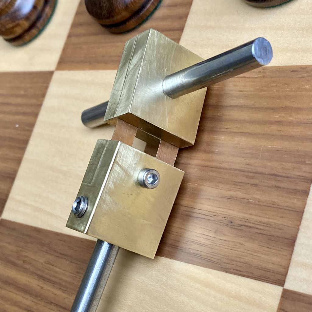
      The hinge itself consists of two 0.004" thick by 0.25" wide strips of beryllium copper. Cutting this using scissors did not work particularly well, as they leave a curled and uneven edge. Thankfully, John Haine (in this forum) made a creative suggestion, which I used: I clamped the cut strips between two 0.25" tool-steel blanks and used an old chisel, laid flat along the steel, to hammer-cut a sliver from the edges. After turning it around, I hammered off the other edge. This worked brilliantly, leaving very clean and straight cuts and a uniform width.

      These strips are held by 0.25" thick two-piece "chops" for stiffness and stability. The upper chops were drilled and reamed for a 3" by 0.25" stainless steel rod. This will sit in a cradle that holds the pendulum.

      The lower part consisted of two pieces: an "L" shaped main body, and a smaller piece that fits into the L. The "L" was used so that I could drill and ream the lower solid part to accept the main pendulum shaft. This was also drilled and tapped to accept two brass-tipped set-screws to fix the shaft in place.

      Cyanoacrylate adhesive was used to join the chops. I'm a little uncertain if this will be sufficient in the long term, but I experimented with it, and it seems very strong. I suppose I could (and probably should) try to insert pins to further fix the strips in the chops. But for now, I'm more worried about ruining the hinge via mishandling!

      The pendulum's shaft is a 0.25" by 36" rod of Invar, a low temperature-coefficient metal that is sometimes used in high-quality clock pendulums. It's quoted as having a 1.2 ppm TC. I may add further temperature compensation, or I may not, as this material should provide decent temperature stability on its own.

      Next steps: I have a 1" by 3" brass disk which I will likely use as the pendulum's bob. This should weigh about 2 lbs, which is rather light for a bob, but the 0.25" shaft is too thin for the usual ~14 lb weight anyway. I also mocked up a cradle for the pendulum in 3D printed form, and will build it in brass, too.

      Here's a picture of the hinge in its chops, the stainless support shaft and the Invar pendulum shaft:

      pendulum hinge.jpg

      It should be a fun and interesting project. 🙂

      Advert
      #4024
      S K
      Participant
        @sk20060
        #653123
        John Haine
        Participant
          @johnhaine32865

          I'm looking forward to later episodes! I'm surprised that you don't think 1/4" invar would support a 14lb bob? 6mm CF tube is perfectly happy with my 10lb+ tungsten bob (though I have now gone for 10mm). 2lb sounds like it would seriously limit Q.

          As you have used a plain ground rod for the transverse support, you could consider just using a flat-topped bracket rather than a "cradle". The Synchronome does this, though it also has clamps to hold the support steady once it has been located and settled. Dong Bateman's clock uses a rather larger diameter support rod and has a pair of ground steel bars bolted to a thick plate as "brackets, with no cradle or clamping.

          We were looking at the Trinity clock recently and the Keeper showed that the mechanism tilts slightly when the tower warms in the sun – this puts the suspension axis slightly out of horizontal and the trunnion bearing which does have a cradle, has too much friction for the pendulum to hang exactly vertical. As a result the pendulum can start to swing in a slight ellipse. Doug's arrangement just allows it to adjust to hang vertical.

          #653131
          SillyOldDuffer
          Moderator
            @sillyoldduffer

            I'm looking forward to this one too. Anything described as an 'Arduinome' must be good!

            And the post instantly generates a new horizon. I toyed with the idea of super-gluing my chops, and did super-glue the brass flange fitted to the end of my carbon-fibre rods. Super-glue is plenty strong enough, but what about its long-term stability? I had in mind the pioneer clockmakers noticing after a few years that Invar is unstable, a problem not entirely fixed today by tweaking the alloy and careful heat-treatment. Although Invar's instability is molecular, causing tiny movements, they're big enough to eventually show up in a high precision clock.

            My first clock's pendulum was noisy, and because a super-glue and carbon-fibre joint moving was a suspect, shades of the Titan submersible, I replaced the joint with a threaded steel rod. The current version is less noisy, but that doesn't prove super-glue was guilty, because I made other major improvements at the same time.

            Whatever we do with pendulums, there's always something else. Decades of fun ahead!

            Dave

            #653149
            S K
            Participant
              @sk20060

              About the bob: It's not that a 1/4" rod can't support more weight, it's that the rod is presumably too flexible for a disproportionally heavy weight. I was considering getting a larger hunk of brass anyway, though, of about 6 lbs. But that would cost $150, so using what I have on hand has its attraction.

              I'll probably stick with a V-shaped cradle, maybe even with a spring retainer. The reason is that I live in earthquake country, and I'd rather not have it crash to the floor. I guess clamping on a flat surface after it settles would be fine too – I'll think about that.

              Good quality fresh, thin cyanoacrylate (not the "gap filling" stuff), used in thin layers on tight-fitting, well-prepared surfaces, can be extremely strong. I absolutely could not break small test pieces apart without heavy tools. I suggest that it's as good as soldering in terms of strength, as well as being much easier. My only doubts are possible long-term failure issues, which I don't have information about.

              The "well tempered" in the thread's title is because I'm aiming at a reasonable balance between accuracy and practicality. I'm not out to make this a world-beating clock. I'm also not planning on an enclosure (I don't have the skill or tools), so accuracy wouldn't be superior just on that point alone. And you will have noted that I used set-screws to fix the pendulum's shaft (I wanted the flexibility to change things). That can't be good either, but it's a tight fit and I could CA that in too if I pleased. Still, of course, I'd like it to keep good time.

              Edited By S K on 21/07/2023 14:50:37

              #653168
              SillyOldDuffer
              Moderator
                @sillyoldduffer

                Posted by S K on 21/07/2023 14:46:50:

                About the bob: It's not that a 1/4" rod can't support more weight, it's that the rod is presumably too flexible for a disproportionally heavy weight

                Good quality fresh, thin cyanoacrylate (not the "gap filling" stuff), used in thin layers on tight-fitting, well-prepared surfaces, can be extremely strong. I absolutely could not break small test pieces apart without heavy tools. I suggest that it's as good as soldering in terms of strength, as well as being much easier. My only doubts are possible long-term failure issues, which I don't have information about.

                Best not in engineering circles to use phrases like 'extremely strong', when numbers are available. Super-glue may be 'extremely strong' compared with spaghetti, but it's not 'extremely strong' compared with most metallic joints.

                Approximate tensile strengths:

                • Cyanoacrylate – about 4000psi, half that in shear, so avoid using glue to support side forces.
                • 60:40 solder is strong for a soft solder, about 7500 psi, roughly twice as strong as super-glue
                • Silver Solder / Brazing is between 4x and 9x stronger than 60:40 (up to about 70,000psi)
                • Welding is as strong as the parent metal. Mild steel at least 62000psi, up to sooper-dooper Maraging Steel at 380,000psi

                There's no doubt super-glue will hold a heavy bob. A 0.25" diameter rod 1" long has a surface area of 0.88sq in. Stuck into a hole in the bob, the joint is in shear, so halve the strength, giving 4000/2 * 0.88, or 1766lbs. Assuming an x3 ish safety factor, a 500lb bob would be OK. My concern is movement, not that the bob will fall off! Bear in mind that clock performance is measured in parts per million, so small pendulum problems show up. (From what I've seen of SK's builds his Arduinome is likely to perform well enough for a tiny fault like unstable glue to show up.)

                I don't recall seeing anything anywhere how much pendulum rods whip. In normal operation I guess not much because the bob accelerates and decelerates smoothly. Clocks with string and chain suspended 'rods' have been made, suggesting a stiff rod isn't essential. However, rods can whip when the pendulum is impulsed, therefore it's best to impulse a pendulum when the bob has maximum kinetic energy, which is when it whizzes past bottom dead centre.

                Dave

                #653184
                S K
                Participant
                  @sk20060

                  Well, if cyanoacrylate isn't "extremely strong," when properly done it should at least be "more than strong enough!" 😉

                  The main problem with a string, even Kevlar, is that it stretches (chains have many issues). When a pendulum is at the far ends of its travel, the downward force of gravity remains downward as always, and so it does not pull in the direction along the string as much. Thus experiencing less force, the string becomes shorter, changing the length of the pendulum dynamically.

                  With a rod and weights of the sizes and masses we are using, I doubt that this should be a significant issue. So probably the impulsing is the greater problem? Really, I'm just working off Matthys' suggestions for shafts and weights.

                  #653222
                  John Haine
                  Participant
                    @johnhaine32865

                    Could we stick to the usual terminology, rod = shaft, bob = weight?

                    Where are you thinking of applying the impulse? The usual xNome configuration is about 30% down the rod, with a heavy bob, and both the original (3/8 invar rod IIRC) and my version (10mm CF tube) suffer from spurious oscillations on impulsing. How much of this is rod flex and how much sideways deflection at the point where the rod and suspension spring meet I'm not sure. With a lighter bob the centre of percussion should move up, so may be less of an issue.

                    #653242
                    S K
                    Participant
                      @sk20060

                      OK, rod / bob it is.

                      I'm now contemplating getting a piece of cast iron for the bob, as it's about 1/3 the cost of brass. That could yield a bob in the 4-6 lbs range given the severe constraints of my puny Sherline lathe.

                      Where to impulse? The old "30% down the rod" rule of thumb seems left over from the use of an escapement + fork. My presumption has been that the center of percussion is the ideal point for the impulse. Even just considering the rod alone would place the CP 2/3 down from the pivot, and lower still including the bob.

                      #653310
                      david bennett 8
                      Participant
                        @davidbennett8

                        s k, are you intending to impulse electromagnetically or electromechanically ?

                        dave8

                        #653311
                        S K
                        Participant
                          @sk20060

                          David,

                          I'm still debating that. I usually cut first and design later.

                          I like electromechanical impulsing as it is more romantic, but it's an objectively worse approach than electromagnetically.

                          #653324
                          John Haine
                          Participant
                            @johnhaine32865

                            Most escapement/crutch assemblies are more like 10% as the movement is much smaller than the pendulum. The 30% is roughly right for the Synchronome, I don't know how much science went into the number. It may be because pallet becomes a large enough target for the gravity arm roller and the travel on the pawl driving the count wheel has about the right travel.

                            **LINK**

                            This article from the latest HJ by Pepi Cima describes some experiments he did with a 'Nome where he impulsed the iron bob with a "frame" coil to one side. There is a photo showing the configuration well. The article is interesting in itself anyway as it shows experimentally why impulsing at BDC is preferred.

                            #653394
                            david bennett 8
                            Participant
                              @davidbennett8
                              Posted by S K on 22/07/2023 14:19:39:

                              Where to impulse? The old "30% down the rod" rule of thumb seems left over from the use of an escapement + fork. My presumption has been that the center of percussion is the ideal point for the impulse. Even just considering the rod alone would place the CP 2/3 down from the pivot, and lower still including the bob.

                              S K you clearly want to try impulsing ar CP, so I think you should go with that. Could you not design it in a modular fashion so that it could be moved to different positions for experiments?

                              dave8

                              #653396
                              S K
                              Participant
                                @sk20060

                                Yes, I had wondered how much the position of the impulse mechanism had to do with practical matters concerning the mechanism itself. Gravity escapements also typically impulse higher up than the CP would be.

                                I had a chuckle at the anachronistic mention of an "IBM PC" (IBM got out of that business eons ago, and who calls them that as a generic name anymore?). And that "frame coil" is a bit odd, too. But the article serves as a caution about how sensitive the pendulum can be to the timing of the impulse – a few ms off is too much, apparently.

                                If going with electromagnetic impulsing, I had imagined a small magnet at the end of a short rod, with an open coil able to accept the length of the rod past the point of the impulse (I've seen this elsewhere). A question about this: Is there a clear optimal position of impulsing the magnet relative to the coil? My first guess is that the magnet should be mid-coil at the time of the impulse, but as the lines of force should be roughly parallel within the coil, I'm not sure it should matter much once it's past the entrance.

                                #653397
                                S K
                                Participant
                                  @sk20060

                                  Dave, yes, I will try for the CP, assuming I can find it or calculate it well enough. But I'll want to dodge the bob, so if it's too near that, I'll move it away from it a little.

                                  As for positioning, I'm thinking of mounting everything on a long, e.g. 40", T-slotted aluminum profile. That way, I can do the gross positioning of components along it pretty easily. But the impulse mechanism might need its own adjustment for the swing, the extent of which would vary depending on its location, etc. A little thought would need to go into that.

                                  Also, while the bottom of the pendulum is the ideal spot for an opto-interrupter, I'd like a clean design, so I might integrate it with the impulse mechanism too, e.g. impulse coil on one side and opto on the other.

                                  #653407
                                  John Haine
                                  Participant
                                    @johnhaine32865
                                    Posted by S K on 23/07/2023 15:38:46:

                                    …And that "frame coil" is a bit odd, too. But the article serves as a caution about how sensitive the pendulum can be to the timing of the impulse – a few ms off is too much, apparently.

                                    If going with electromagnetic impulsing, I had imagined a small magnet at the end of a short rod, with an open coil able to accept the length of the rod past the point of the impulse (I've seen this elsewhere). A question about this: Is there a clear optimal position of impulsing the magnet relative to the coil? My first guess is that the magnet should be mid-coil at the time of the impulse, but as the lines of force should be roughly parallel within the coil, I'm not sure it should matter much once it's past the entrance.

                                    I think the coil shape is quite logical given the size of the bob – it just maximises the amount of ferrous metal exposed to the field.

                                    Impulse timing – actually it doesn't matter as long as it's constant. If it isn't constant then it can become a source of error if either timing of amplitude of impulse changes. The grasshopper deliberately impulses late to provide some compensation for other variables.

                                    I can't visualise your coil and magnet arrangement – any chance of a sketch?

                                    #653429
                                    SillyOldDuffer
                                    Moderator
                                      @sillyoldduffer
                                      Posted by S K on 23/07/2023 15:38:46:
                                      A question about this: Is there a clear optimal position of impulsing the magnet relative to the coil? My first guess is that the magnet should be mid-coil at the time of the impulse, but as the lines of force should be roughly parallel within the coil, I'm not sure it should matter much once it's past the entrance.

                                      I guess it depends on the orientation of the coil relative to the bob.

                                      Cima (and I) both have side coils. These don't have a mid-coil position, as I understand the question, so the impulse should simply be applied when the bob is at max speed (i.e. at BDC)*

                                      I guess a coil laid under the bob is time sensitive. If fired late, I imagine the magnetic field braking the bob, rather than accelerating it. Therefore the impulse should. be timed to start somewhat before BDC and to end at BDC exactly.

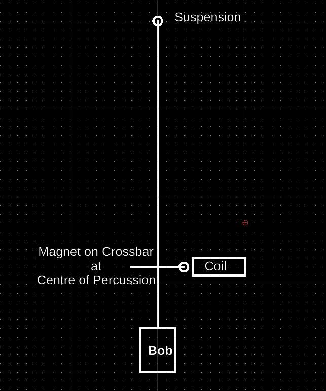
                                      Are you proposing magnet that flies inside a coil like this:

                                      crossbarbob.jpg

                                      If that's what's proposed, I think a magnet pulled into coil configuration behaves like a flat coil under the bob, in that energising the coil after the permanent magnet has passed coil centre will act as a brake. (In a solenoid maximum magnetic field occurs in the centre of the coil.)

                                      Incidentally, I use an iron-cored coil because it fits into a much smaller space and produces a stronger magnetic field. However, the core slows down development and collapse of the magnetic field, which I imagine to be late with soft edges compared with the sharp on/off field produced by an air-cored electromagnet. Anyone know if that matters! Another mystery…

                                      Dave

                                      * Reading the HJ article linked by John ruined my day. It reminded me I forgot to 3D-reprint my magnet and IR beam holder! Due to a mistake, the current holder isn't long enough to impulse at BDC as designed. Fixed ages ago in CAD, but never in the real world. Aargh!!!!

                                      #653435
                                      S K
                                      Participant
                                        @sk20060

                                        John: Perhaps you mean "consistent?"

                                        I propose using a hollow (coreless) coil. I have an old relay somewhere whose coil I can likely scavenge, or else I'll 3D print a bobbin for one.

                                        I've just bought two 1/4" by 1/4" cylindrical grade 52 Neodymium magnets for this purpose, either for use in a pair or to have an extra. (I also splurged for brass rather than cast iron for the bob.)

                                        The picture above is approximately what I'm thinking of, with the magnet on a short stick so there's space for it to continue through the hollow coil without the rod hitting it. I've seen this approach used somewhere else, I think using a horn shaped piece of steel rather than a magnet, but I can't find it now.

                                        My question is where the magnet should be relative to the coil at the point of the impulse (approximately). I was thinking inside it, at the center of the coil, but now I see that's wrong. I suppose needs to be while near the outside, e.g. at the entrance to the coil.

                                        In the alternative, I don't like the idea of a "flat coil under the bob," but I do like John's Helmholtz coil approach. If the latter, I think I could use the two magnets facing out from the rod with their poles in the same direction (i.e. NS-NS), as I don't have the opportunity to put one inside the rod as John did. Maybe that's a more elegant solution.

                                        … or maybe I'll do electromechanical. As I said, I tend to cut first and design later. 😉


                                        Edited By S K on 23/07/2023 20:02:15

                                        #653443
                                        S K
                                        Participant
                                          @sk20060

                                          I looked at whether it's worth adding temperature compensation to an Invar rod. (This is after I ordered a brass tube to use as the compensator.)

                                          The temperature coefficient of 360 brass is 20.5 ppm, while that of Invar is 1.2 ppm. So, given a 35" net rod, about 2.049" of brass (acting opposite the Invar) can be added to reduce the net TC by 100x.

                                          But here's the problem: The compensation is so sensitive that, if you are off that mark by a rather small amount, say 0.1", you are only going to make it worse. It's not that cutting a tube to an exact length is terribly hard, but it's the net assembly that may easily incorporate an error that small. Using a lower TC compensator can help with this sensitivity, but that would require a longer rod, or you will be pushing the bob up much higher.

                                          I don't think it's worth the risk, at least unless it can be adjusted finely, and then only with a lot of trial and error measurement over very long time periods, too.


                                          Edited By S K on 23/07/2023 22:21:17

                                          #653464
                                          S K
                                          Participant
                                            @sk20060

                                            Maybe it's easier to do compensation than I first thought.

                                            I could put a spring-steel pin through the bottom of the rod, and support the bob (which will be approx a 3" diameter cylinder that is 3" high) by about 0.55" of the same 360 brass (2.05"-3"/2). I could ream both the support and bob 0.001" large, which should be a decent sliding fit that doesn't wobble. That sounds easy to do accurately.

                                            Edited By S K on 24/07/2023 03:41:43

                                            #653473
                                            Joseph Noci 1
                                            Participant
                                              @josephnoci1
                                              Posted by SillyOldDuffer on 23/07/2023 18:50:37:

                                              …………………..

                                              Incidentally, I use an iron-cored coil because it fits into a much smaller space and produces a stronger magnetic field. However, the core slows down development and collapse of the magnetic field, which I imagine to be late with soft edges compared with the sharp on/off field produced by an air-cored electromagnet. Anyone know if that matters! Another mystery…

                                              Dave

                                              It's not the addition of the core that 'slows' anything down. The iron core only increases inductance (it may 'focus' the magnetic field as well, but that is incidental). Di/Dt increases (due to back EMF) with inductance and so a reduced rate of increase of I ( amps) is the culprit. Simply increase the applied voltage and fit a series resistor to limit final current.

                                              For (soft) iron cores in a current carrying coil of wire :

                                              The magnetic field is not amplified – it is constrained or focused by the core. Di/Dt limits rate of change of the magnetic field, which is proportional to rate of increase of current in the coil. At equilibrium, current is V/R of the coil.

                                              Increasing the applied voltage overcomes the opposing EMF which limits the rate of change of current. Removing the applied voltage results in a high emf generated across the coil as the collapsing magnetic field tries to maintain the current flow through it ( and via a very high impedance [open circuit] path between its terminals). The magnetic field survives the longest if the terminals are shorted immediately after removing the applied EMF. Fitting a voltage spike suppression diode across the coils terminals 'shorts' one half of the oscillation of the decaying voltage, maintaining a high current in the coil, allowing the magnetic field to survive longer as well.

                                              In summary, to speed up the rate o increase of the magnetic field, fit a series resistor (to limit final current) and increase the applied voltage( to increase volt/seconds). To increase decay rate, upon removal of the applied voltage , place a resistor across the coils terminal to dissipate the energy in the coil as the field collapses. The current flow must be dissipated, not maintained.

                                              #654136
                                              S K
                                              Participant
                                                @sk20060

                                                Joseph, et. al.,

                                                Would you have any advice about winding a coil for this purpose? E.g., what aspect ratio, gauge, no. of windings, etc? Really, anything that might help?

                                                I have a couple of 1/4" neodymium magnets and 4 ounces of 30 gauge magnet wire on hand for this purpose (bought without much thought. I can 3-D print bobbins in arbitrary shapes.

                                                Thank you.

                                                #654150
                                                John Haine
                                                Participant
                                                  @johnhaine32865
                                                  Posted by S K on 23/07/2023 19:50:58:

                                                  John: Perhaps you mean "consistent?"

                                                  …..

                                                  The picture above is approximately what I'm thinking of, with the magnet on a short stick so there's space for it to continue through the hollow coil without the rod hitting it. I've seen this approach used somewhere else, I think using a horn shaped piece of steel rather than a magnet, but I can't find it now.

                                                  My question is where the magnet should be relative to the coil at the point of the impulse (approximately). I was thinking inside it, at the center of the coil, but now I see that's wrong. I suppose needs to be while near the outside, e.g. at the entrance to the coil.

                                                  In the alternative, I don't like the idea of a "flat coil under the bob," but I do like John's Helmholtz coil approach. If the latter, I think I could use the two magnets facing out from the rod with their poles in the same direction (i.e. NS-NS), as I don't have the opportunity to put one inside the rod as John did. Maybe that's a more elegant solution.

                                                  … or maybe I'll do electromechanical. As I said, I tend to cut first and design later. 😉


                                                  Edited By S K on 23/07/2023 20:02:15

                                                  Yes, consistently constant.

                                                  I don't think you will need a core at all. , the required force is minimal and a core just creates an attractive force with the magnets that will perturb the pendulum.

                                                  You may have seen the "magnet in a coil" in one of Ned Bigelow's 2-pendulum designs.

                                                  By the way, though a core may not change the field it does change the flux! It's flux that generates the force.

                                                  As for bobbin shape, look at Bigelow's design.  But I think you want a solenoidal coil considerably longer than the magnet and the magnet should be central when impulsed.


                                                  Edited By John Haine on 28/07/2023 18:38:57

                                                  #657405
                                                  S K
                                                  Participant
                                                    @sk20060

                                                    A very small update:

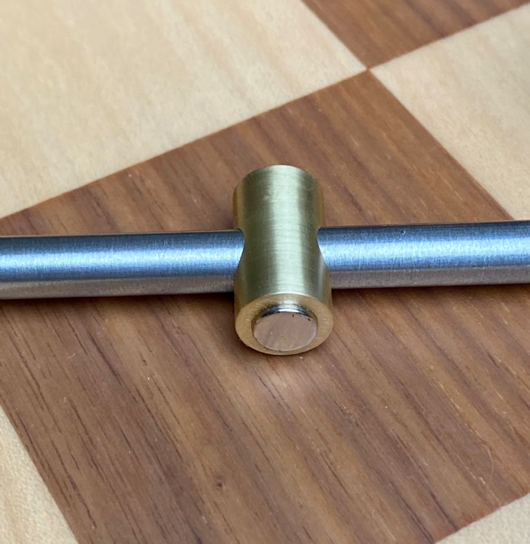
                                                    I've decided on electromagnetic impulsing using Helmholtz coils. Since my rod was not hollow, I made a magnet holder capable of holding two magnets on opposite sides of the Invar rod. These are 1/4" diameter by 1/4" long grade 54 neodymium magnets in a NS-NS arrangement. They essentially forming one larger magnet with the 1/4" diameter rod in the middle acting as a bridge. The magnets grip the rod strongly, but the assembly can be positioned easily:

                                                    img_4960.jpeg

                                                    I noted that the magnets form a surprisingly strong compass, and wonder if that might apply a twisting force to the rod large enough to influence the pendulum? I think I'll close my eyes to that possibility.

                                                    Edited By S K on 22/08/2023 01:16:50

                                                    #657407
                                                    Michael Gilligan
                                                    Participant
                                                      @michaelgilligan61133
                                                      Posted by S K on 22/08/2023 01:15:15:

                                                      A very small update:

                                                      […]

                                                      I noted that the magnets form a surprisingly strong compass, and wonder if that might apply a twisting force to the rod large enough to influence the pendulum? I think I'll close my eyes to that possibility.

                                                      Edited By S K on 22/08/2023 01:16:50

                                                      .

                                                      Nicely done yes

                                                      … ‘though I fear that thought ^^^ may come back to haunt you.

                                                      MichaelG.

                                                    Viewing 25 posts - 1 through 25 (of 96 total)
                                                    • Please log in to reply to this topic. Registering is free and easy using the links on the menu at the top of this page.

                                                    Advert

                                                    Latest Replies

                                                    Viewing 25 topics - 1 through 25 (of 25 total)
                                                    Viewing 25 topics - 1 through 25 (of 25 total)

                                                    View full reply list.

                                                    Advert

                                                    Newsletter Sign-up