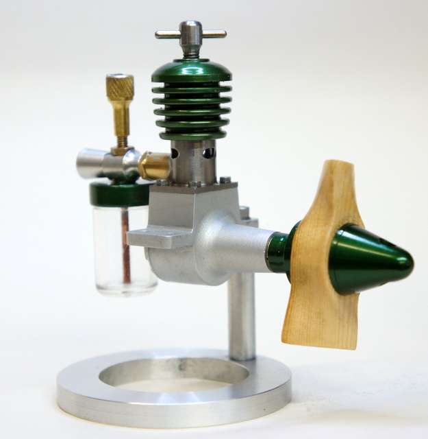
I am a fairly regular visitor to the very informative site, for those interested in model I/C engines, run by Adrian Duncan. http://www.adrianduncansmodelaeroengines .com. A few months ago I discovered information and drawings for this 1950s design engine on it and the fact that it was possible to make it from bar stock, I decided it was to be my next project. The article mentions it has been made by several of the “Motor Boys” from the late Ron Chernich’s Model Engine News site and includes photos of finished engines. In particular it was the photo of Ken Croft’s engine that attracted me, with its Britsh Racing Green anodised parts, so it is his engine that I have copied.
MOD Edit Weaver Plans
Two sets of drawings are on the site. The original set, all on one page, are from an article published in the, now defunct, Model Maker magazine of June 1952 and are of their time. IE-Hacksaw Crankcase to shape! The other set of six drawings are CAD and produced by Ron Chernich. When I first studied these, I thought the Cylinder was too thin around the area that contains the fuel transfer drillings, also, I do not like forward facing exhaust ports and made a mental note to change these. It is probably an “age thing” as when I came to machine the Cylinder, I followed the drawing dimensions! If anyone is interested in making this engine, I would recommend doubling the thickness of the Cylinder below the cooling fins and not have the forward facing exhaust port, but increase both sideports forward, to compensate. This eliminates the problem that the Gudgeon pin has two apertures to possibly catch in to, as well as not having oil blast onto the prop when running. I always taper fit Gudgeon pins, by using the taper on a hand reamer, to make a tight fit one side of the piston.
The fuel transfer drillings are 5 off. Drilled by putting a tight plug into and flush with, the bottom face of the Cylinder. Then drilling down with a No 52 drill at the joint of the plug to cylinder to the required depth. This leaves five semi-circular grooves after removal of the plug, The drawing notes call for these to join with a “belt”. No dimensions or a scrap view of this feature is given. There is mention of using a saw shaped tool to produce it. I presume it is a circular groove around the bore so fuel is injected in a complete ring, rather than from the five semi-circular drillings. I decided not to try to cut this groove, as 1) I do not have a tool small enough and of the correct shape and 2) I thought the possibility of cutting through the thin cylinder wall was too risky. Without it, the finished engine starts easily,runs for two minutes on the tank of fuel and with a 9×4 inch APS nylon prop, is running at 5800 RPM, on Technics 1000 fuel, in the attached photo. Initially, I fitted a 6×4 APC nylon prop and although it was firing easily, it would not go over TDC whatever I tried. Normally reducing compression cures this, but not this time. No tight spots either. The engine was originally designed for tether car racing. The old drawings include a fly wheel and I wondered if the timing is set up for fly wheel use, so I changed to the heavier 9×4 prop and away it went. Success!
I will probably make a nipple for the fuel pipe, so that I can use the larger tank fitted to the test rig, Then I can have some longer running times with it and a chance to “play” before it runs out of fuel.
Keith.
 KEITH BEAUMONT.


