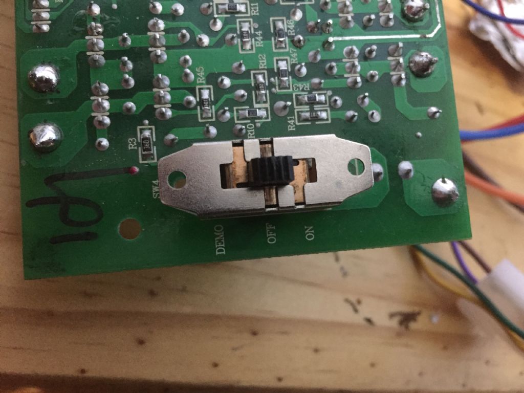
A while back I took on a community project to repurpose a robotic toy for use by a 'performance artist'. I've got the mechanics sorted out, but I now realise that I need to move the toy's control switch from the 'brainboard' to a remote location. This is the switch from the top:
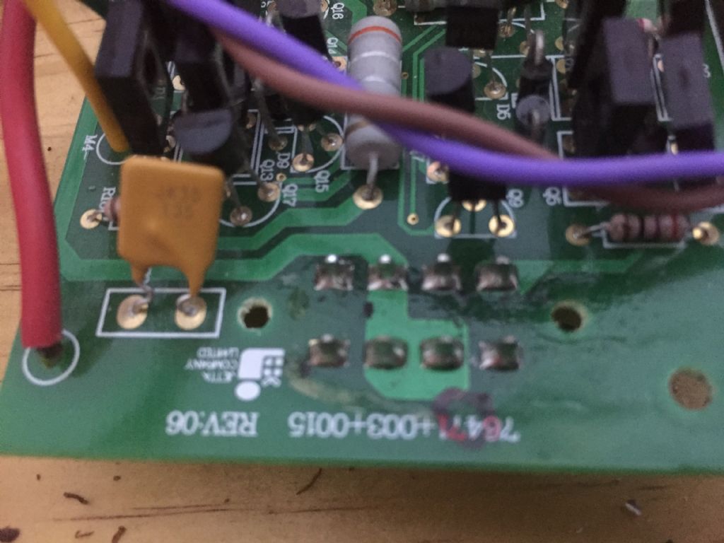
and from the rear:
My first question is: What are the odds on me removing the switch from the board using solder wick without knackering anything, given that I've zero experience with this technique?
Second Q is whether I even need to remove the switch – perhaps if I left it in the 'off' position I could just take wires from appropriate pins on the back of the board and replicate the 'demo' and 'on' states with a new switch.
Having undone many a component from many a PCB or hard-wired circuit…
It won't be easy as solder-wick might not slurp it all up. A vacuum-type solder-sucker might be better.
Try it, anyway; but I would advise using only as much heat as necessary, and letting the work cool down after each pin. There doesn't seem to be anything too sensitive to heat close to the switch, but you don't want to risk lifting the tracks off the board.
If the switch is to be moved to a new location anyway, your second idea may well be effective. If you use that, secure the wires to the board close to the pins, making use of what seem to be two holes. Fit a blanking-plate to prevent accidental operating of the original switch. At least this approach would allow the circuit to be restored to original, if thought necessary in future.
Hi Robin, one problem you have is the board has a printed circuit on both sides of the board and the switch may well have been soldered in on both sides as well, so it will be more difficult to de-solder by either of the two methods and the circuit may not allow you to add a remote switch with that one still in place as it it is a three position switch. You will have to check that the switch has a totally off position that doesn't restrict a remote switch to be added, otherwise you may have to cut the switch off mechanically or wrecking the case and removing the switching parts.
It may be easier to cut through the pins on the switch and get it out of the way be fore attempting to desolder the pins and then fitting a replacement remote switch – less metal to heat up and less chance of damaging the board.
You will need to 'nibble' away at the pins with some fine nosed cutters – but the second side should be easier as you will be able to lift the switch slightly to get better access.
A test needs to be made on one pin to check if the switch pin is a tight fit in the hole or the hole is through plated as removal is more difficult in these cases. One way to remove the solder is to heat the joint and then quickly tap the board on the bench which will make the fluid solder splash out. Start gently and preferably on a pin that has no tracking connection to save damaging the board.
If the pins are a tight fit the technique I've found best is to flood the pins with more solder and extract the device while the solder is fluid rather like the reverse of flow soldering. However this requires a degree of preparation as it needs to be done quickly. The switch body needs to be held in a vice and/or levering devices put in place to prise the board off the switch. Since in your case there are two rows of pins the soldering iron will need to be moved quickly down each row alternately until the solder around each pin is fluid and before starting extraction. The process may need to be done in stages as the board/switch may not come out symmetrically.
Best to use a good quality temperature controlled iron at around 300C to ensure solder become fluid but not too high a temperature to scorch the board.
I believe the smart option is to get a replacement switch and connect by soldering flexible wire tails (6) to the original switch pins where they exit the component side of the board.
If the PCB is a close fit in the box there is sufficient clear area on the board where a hole can be drilled for the wires to pass through.
If the original switch is still accessable you will have to fix it in the OFF position or make a cover.
The switch can certainly be removed with soderwick, I have found that it can be useful to add fresh solder if the wick does not remove all the solder. It would be worth getting the feel for using soderwick on some scrap boards before getting into trouble on the board you need to use. It would be worth verifying the configuration of the switch before it’s possible destruction by the desoldering operation. It looks most likely to be a double pole changeover DPCO switch.
That looks to me like a three way switch with the centre position leaving all three pole isolated. Your best solution is to leave the switch in situ and solder 3 wires to the pads. he external switch can then be attached to the other end and the the system will work correctly so long as the switch is in the centre position.
It may be naughty, but if you can avoid the solder bridgeing tracks melt the solder then give a quick blast of compressed air, wear safety glasses when doing this ! The switch may be ON in all positions, to different functions so leaving in place may not be an option. Good Luck. Noel.
The switch may be ON in all positions, to different functions so leaving in place may not be an option. Good Luck. Noel.
The info on the silk layer says 3 positions are ON OFF and DEMO with the centre marked off so it's pretty certain that the switch osolates all pads in the centre position. Easily checked with a meter.
If, as you say, you have no experience unsoldering something like this and if – as seems likely – the switch contacts are isolated in the centre position, then it's a no-brainer to me: leave it in place and wire another switch. Essentially zero risk.
Even if the contacts are not isolated, you are more likely to fail than succeed in unsoldering particularly if pads on the opposite side are used (can't tell) with vias feeding through. In that case, I personally would cut through the switch casing with a small hacksaw and remove the whole switch (or its innards) without unsoldering.
(If there are pcb pads for the switch on the opposite side of the board with vias, then you would need to retain – or recreate – the via connections if unsoldering. Another reason to leave it in place and wire another switch).
The switch may be ON in all positions, to different functions so leaving in place may not be an option. Good Luck. Noel.
The info on the silk layer says 3 positions are ON OFF and DEMO with the centre marked off so it's pretty certain that the switch osolates all pads in the centre position. Easily checked with a meter.
regards Martin
Hi, from my (non extensive but over many years) experience, you can't be certain about anything that looks like a switch is configured in such a way that it must be what you would expect. The switch in the photo is a three way, but it has eight pins, which could mean that in the off position, it may be holding up to four different aspects of the circuit off and just adding a new switch without removing the old one or it's contactor components, the circuit might not work or it may even short other parts out, so the circuit needs to be checked out before just adding another switch. More or less what Noel has said.
Thanks for advice. I had hoped that I might be able to get away with leaving the switch in position, but after reading exchanges between Nick, Martin and Noel:
Posted by Nicholas Farr on 08/05/2022 21:01:51:
Posted by Martin Kyte on 08/05/2022 13:07:23:
Posted by noel shelley on 08/05/2022 11:57:23:
The switch may be ON in all positions, to different functions so leaving in place may not be an option. Good Luck. Noel.
The info on the silk layer says 3 positions are ON OFF and DEMO with the centre marked off so it's pretty certain that the switch osolates all pads in the centre position. Easily checked with a meter.
regards Martin
Hi, from my (non extensive but over many years) experience, you can't be certain about anything that looks like a switch is configured in such a way that it must be what you would expect. The switch in the photo is a three way, but it has eight pins, which could mean that in the off position, it may be holding up to four different aspects of the circuit off and just adding a new switch without removing the old one or it's contactor components, the circuit might not work or it may even short other parts out, so the circuit needs to be checked out before just adding another switch. More or less what Noel has said.
Regards Nick.
Edited By Nicholas Farr on 08/05/2022 21:03:10
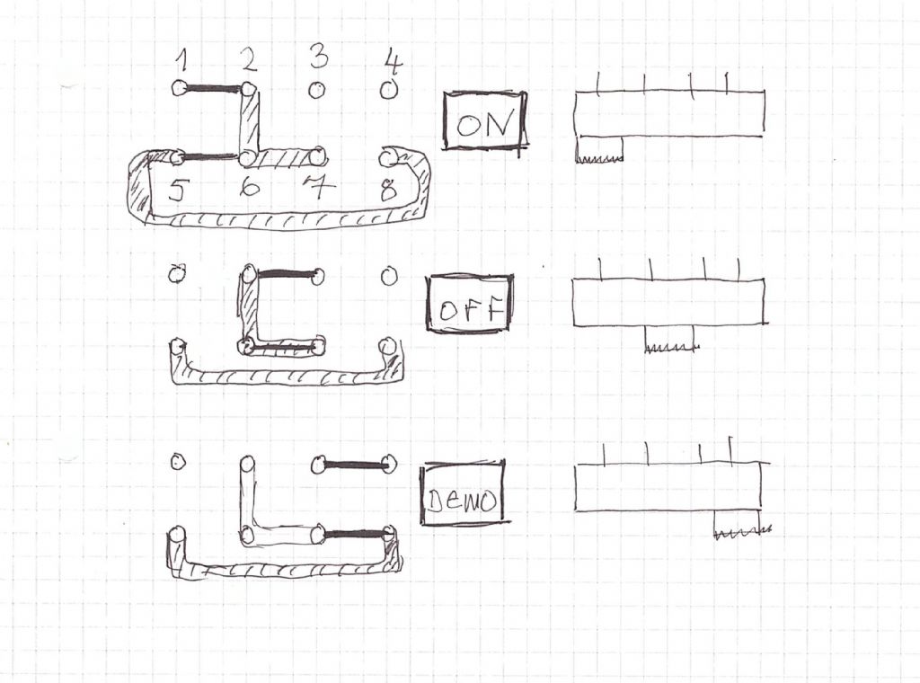
I took a multimeter to the switch and found:
The hatched things are pcb tracks – I can see the L – shaped track connecting 2,6,7 on the component side and infer the existence of one between pins 5 and 8 because they are connected at all switch positions. Presumably on the other side, obscured by the switch body. I have also inferred the switch connection between 6 and 7 in the 'off' position – symmetry seems to demand it!
The problem with leaving the existing switch in the 'off' position and wiring up another one seems to be that pins 2 and 3 will remain connected in 'on and 'demo' modes. Maybe that wouldn't matter but I can't be sure.
I'll have a go with the wick, but if it doesn't look like it'll work I'll resort to Nick's suggestion of destroying the switch – drastic as it seems it might actually be the least risky option.
If anyone's interested the board came from a (now obsolete) Hasbro FurReal toy pony. You can see it here. They cost over 1000 USD when launched I'm told!
What I do in a situation like this is use a big iron with a wide tip, hold the board in the vice in a suitable orientation and apply some force trying to tip it and pull out the 4 pins on one side. Apply the iron to the 4 pins under load, run it back and to if it's not wide enough and you will feel a click as it moves. Then go to the other side, and back and to until it is out. Don't remove the solder first you need something to melt, in fact adding extra solder sometimes helps
Hi Robin, your sketch is good and it can be seen in your photo that there is a track connected to pin four on the component side, which suggests that there's a possible track on pin three under the switch connected to something else. This is the trouble with things like this, they can hide tracks and connections under them.
I would cut through the switch casing with a small hacksaw and remove the whole switch (or its innards) without unsoldering.
(If there are pcb pads for the switch on the opposite side of the board with vias, then you would need to retain – or recreate – the via connections if unsoldering. Another reason to leave it in place and wire another switch).
Agree. Use the remains to solder the wires onto for the exterior switch.
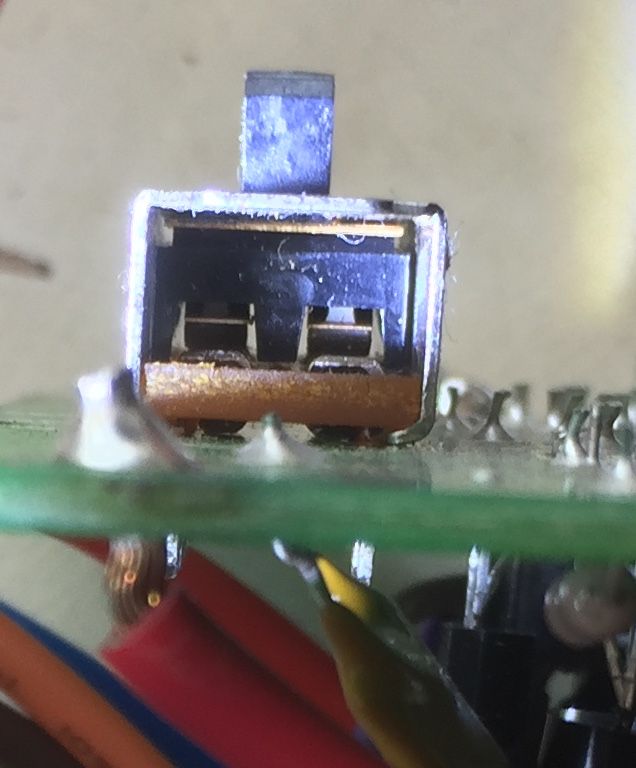
-Thanks for further advice. Looking more closely at the switch:
it seems likely that if I bend the sides outwards the whole thing will fall apart and reveal pads onto which I can solder.
I'm having trouble finding a replacement though – searching on DPCO as suggested by Mike brings up switches with two rows of three pins rather than the type I need (see earlier sketch). Does anyone know what the configuration I want is called?
Well, I found some 8-pin DP3T slide switches on Amazon (for the princely sum of £6.49 for 20!) and have ordered them. They'll probably be pretty cr@p at that price, but hopefully at least one will be for OK enough for this job.
In the course of my researches I came across a lot of 6-pin slide switches described as DP3T so obviously the designation doesn't specify the switch uniquely.
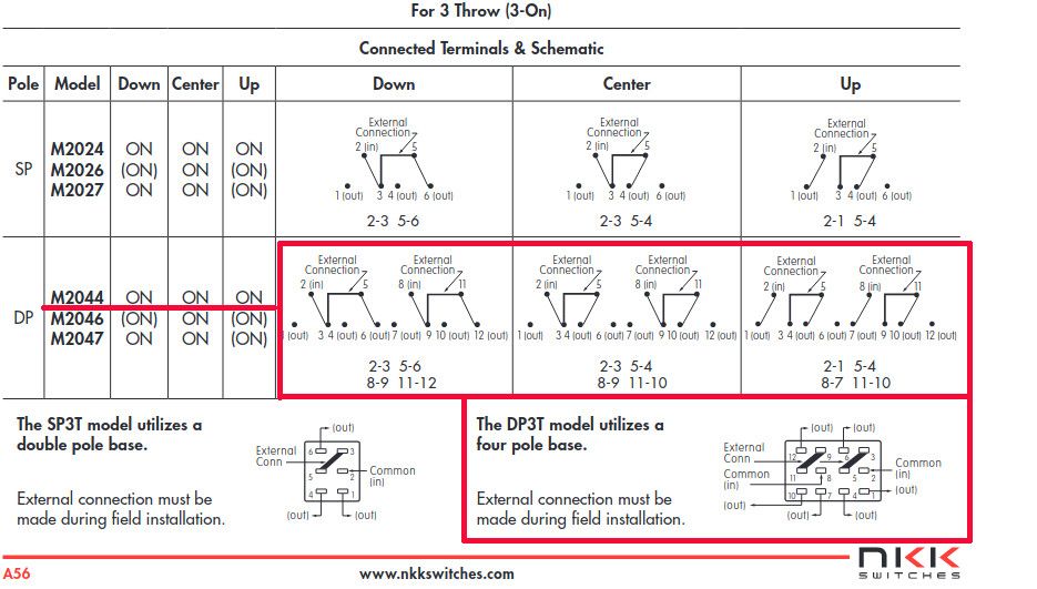
I also came across a 12-pin DP3T On-On-On toggle switch. A toggle switch would actually be preferable, but I can't see how this one could be made to work in my application. Here is the schematic:
I can't satisfy myself that it's impossible though! If anyone can see a way that it could work or reassure me that it's impossible that would be educational.