A Tower Clock project

Advert

A Tower Clock project

Home Forums Clocks and Scientific Instruments A Tower Clock project

Viewing 12 posts - 26 through 37 (of 37 total)
  • Author
    Posts
  • #569419
    John Haine
    Participant
      @johnhaine32865

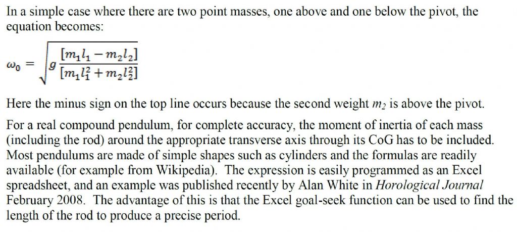
      Here's a simple formula that works for light rods and compact weights. Taken from an article I wrote in 2008 for Horological Science News.

      compound.jpg

      Hope this helps.

      Advert
      #569423
      Peter Cook 6
      Participant
        @petercook6

        Thanks Both – I feel more brain ache coming on!

        #569472
        bernard towers
        Participant
          @bernardtowers37738

          Michael G, casting was done in a cope and drag box the traditional way. PS. The risers (3/4 dia) have been used to make bushes for other projects and hav machined up well with no inclusions!!

          #569481
          Michael Gilligan
          Participant
            @michaelgilligan61133
            Posted by bernard towers on 02/11/2021 18:17:55:

            Michael G, casting was done in a cope and drag box the traditional way. PS. The risers (3/4 dia) have been used to make bushes for other projects and hav machined up well with no inclusions!!

            .

            Thanks again, Bernard … I was just interested because some of my ancestors were involved in Brass casting, and I am aware that such shapes do lend themselves to being cast single-sided, in ‘a mere scrape in the sand’.

            MichaelG.

            #581410
            Peter Cook 6
            Participant
              @petercook6

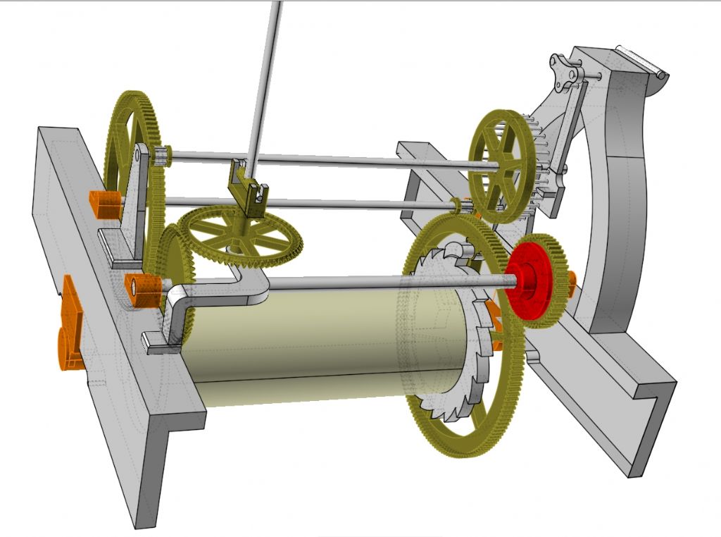
              In case anyone is interested!. It has been a bit cold in the workshop for progress on the "other projects", so I have amused myself by developing the design for the church clock model. Rather than the original idea of having the chime triggered twice (rather than the four times of the original), I did some spread sheeting to develop an alternative time train that gives a once per hour minute shaft, and for which the wheels are fairly close to scale – I chose 6mm = 1" as I prefer to work in metric, but the clock is clearly imperial dimensions. So far only the time train is close to a finished design, the chime & strike trains will be closer to the original as the gear ratios can be retained.

              The model so far is

              church clock time train.jpg


              Time Train
                                       Church Clock Model
              Great wheel Teeth 120             150
              Rotates Every      3 Hours     3 Hours
              Ratchet Teeth         20                 20
              1st Pinion Pins       10                   8
              2nd Wheel Teeth     90               116
              Rotates Every min  15                   9.60
              2nd Pinion Pins         8                  8
              Escape Wheel Pins 35                35
              Rotates Seconds     80                39.7
              Pendulum Period secs 2.29         1.13
              BPH                       3150             6343
              Minute Wheel Teeth 40                 50
              Rotates            Once per hour Once per hour
              Bevel Gear Teeth    76                   60

              Dimensions 1" = 6mm
                                            inches          mm       Scale
              Great Wheel           11.75           76        1.08
              2nd Wheel                8.5             59         1.16
              Escape Wheel          5.5             32         0.97
              Minute Wheel           4.0              26         1.08
              Bevel Gears             7.5              28          0.62
              Drum                        6.0              36          1.00
              Pendulum Length   51.20          320          1.04

              Using MOD 0.5 for the gears, the second wheel is a fair bit (16%) bigger than scale which required the escape arbour to move to one side, at which point it clashed with the minute arbour drive wheel, so the bearing mounts needed lengthening to raise it up to maintain depthing. The output bevel gears also needed to be made a bit smaller to avoid a clash with the second wheel, but otherwise things are fairly close to scale.

              The escape wheel teeth on the original are flattened and about 1/8" thick. To scale they look rather fragile at 0.75mm, so I have used 1mm pins and modified the pallet spacings to suit (I hope!). The plan is to make the arbours from silver steel and harden the pivots. All bearings are brass. Several parts (the frame, the escape arbour, bevel wheel bearing supports and the pendulum support are clearly cast iron. They will be fabricated from steel ( silver soldering is a skill I will need to acquire). The winding ratchet also looks to be cast and that together with the similar parts for chime and strike, plus the strike cam have some complex curves that I will need to work out how to make. I might see if I can find a local laser cutting organisation willing to make small one-off parts for a reasonable cost (unless anyone has a cheap desktop laser cutter capable of cutting 4mm steel plate going spare).

              As always, comments and suggestions gratefully received.

              Edited to correct tabulation of table ( I hope) 

              Edited By Peter Cook 6 on 20/01/2022 17:50:07

              Edited By Peter Cook 6 on 20/01/2022 17:52:38

              #590524
              Roger Best
              Participant
                @rogerbest89007

                That seems to have got very complex! disgust

                #590579
                bernard towers
                Participant
                  @bernardtowers37738

                  I have to agree with Roger, keep it simple its still fascinating to watch when finished.

                  #616729
                  Peter Cook 6
                  Participant
                    @petercook6

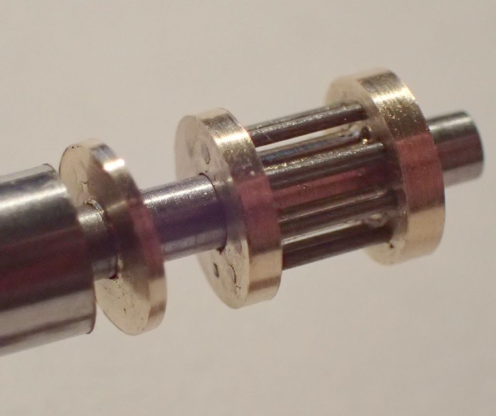
                    The project has made its first swarf. Having decided on Mod 0.5 for the wheels of the time train, before ordering lots of material, I thought I should experiment and see if I could make a Mod 0.5 8 tooth lantern pinion. 6mm diameter, 4mm width (for a 3mm wheel) and using 0.51mm piano wire (nearest to Mod * 1.05 as per Wilding I could get). Included a cap to cover the end. Currently loose on a dummy arbour.

                    lantern pinion.jpglantern & ruler pa090282.jpg

                    Worked well. Finish needs work, and the wire for the real ones will need polishing. But a win. Now I need to find out if it will run against a Mod 0.5 wheel.

                    #616732
                    Martin Kyte
                    Participant
                      @martinkyte99762

                      You should (and perhaps have) realised that one of the advantages of a flat frame is the ability to have adjustable bearing bushes so that engagements can be set on the clock without depthing. The design should take allowance of this so that the clock can be set up from barrel to escapement as you go so that moving one bush doesn't throw three other clearences out.

                      regards Marin

                      #772257
                      Peter Cook 6
                      Participant
                        @petercook6

                        An end of year update on progress. The frame and the pylons which hold the wheels and levers are finally made. They still need brass bearings added and fixing to the frame but that will happen once (if ever) the wheels have been cut and  depthed as they are fitted.

                        Frame and parts

                        The pylon uprights and the ratchets were laser cut by a local firm in 4mm steel plate. The bases for the pylons were machined from an off-cut of the angle used to form the frame. Joined with 2mm roll pins and JBweld.

                        At last I feel I am actually making progress. Next year’s resolution is to take my round tuit in both hands and start wheel cutting!!

                        #772270
                        Martin Kyte
                        Participant
                          @martinkyte99762

                          Would you consider pinion steel for your lantern pinion instead of piano wire. It’s semi hard and smooth.

                          #772278
                          Peter Cook 6
                          Participant
                            @petercook6
                            On Martin Kyte Said:

                            Would you consider pinion steel for your lantern pinion instead of piano wire. It’s semi hard and smooth.

                            Probably Martin, I have some pinion wire on stock, so I will see what I have when the time comes. At the time I only had the piano wire in the size I needed, and as it was a test piece the material was less important than the machining practice.

                          Viewing 12 posts - 26 through 37 (of 37 total)
                          • Please log in to reply to this topic. Registering is free and easy using the links on the menu at the top of this page.

                          Advert

                          Latest Replies

                          Viewing 25 topics - 1 through 25 (of 25 total)
                          Viewing 25 topics - 1 through 25 (of 25 total)

                          View full reply list.

                          Advert

                          Newsletter Sign-up