Hi!!
Since the visiting frequency is fairly high on this thread, I thought that I could publish a short manufacturing description as well. Unfortunately a lathe is necessary for some of the parts, but for the imaginative other solutions are probably available. The idea is to provide a little inspiration and some ideas.
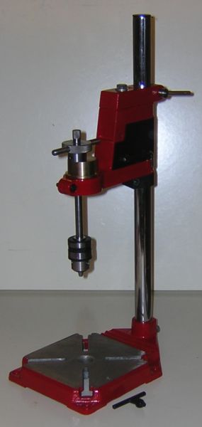
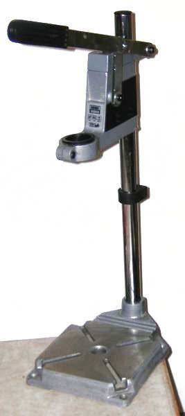
As a starting point I used a simple drill stand, …
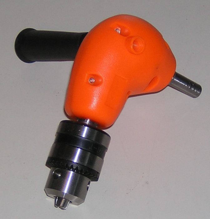
and one of those simple angle-gears for hand-held electrical drills (the chuck was nice).
Also some parts from the famous store of odd bits-and-pieces.
I did not think that it was necessary to keep the drill-stand feed function, so I removed all those parts to get a clean “head”. Next in line was to make the lump that is clamped in place instead of the drill. Mine was made out of brass, but anything from cast iron to aluminium will work.
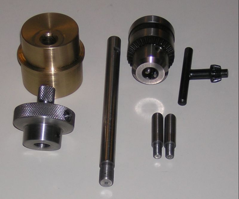
The brass block is the main part. Note that the hole for the chuck axle is off center and quite close to the outer diameter. This will give more room for the “wings”. The knob in front of the block have two knurled diameters to provide suitable momentum for smaller taps. In addition I drilled two holes opposite each other (or one right through the knob) in the larger knurled portion for two stub wings as an aid for turning larger taps. There is also one cross-hole below the larger knurling for two set screws locking the knob to the axle.
To the right of the knob we see the axle, 100 mm (3/8″) dia and about 150 mm (6″) long with a 3/8″-24 UNF thread for the drill chuck. Make the threaded portion the same as the one on the angle gear. Further to the right are the chuck key and the two stub wings. The wings are made from a piece of 8 mm (5/16″) round bar with M6 or 1/4″ BSW/BA thread. make the ´wings just long enough to clear the head casting with a safe distance.
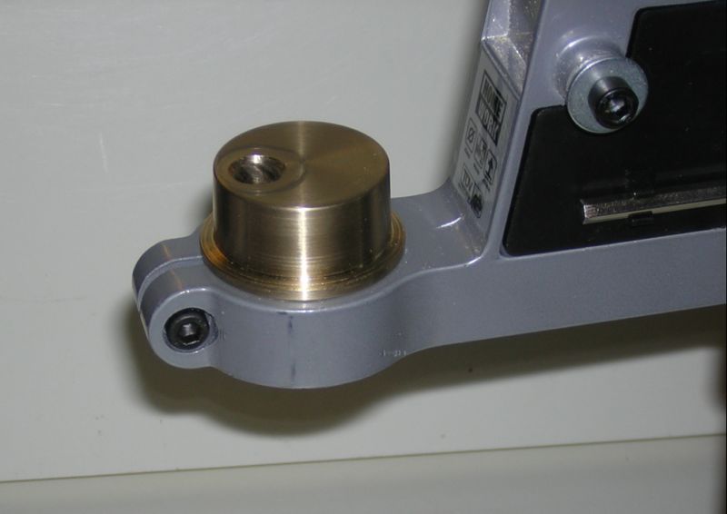
This is how it looks when the block is clamped in place.
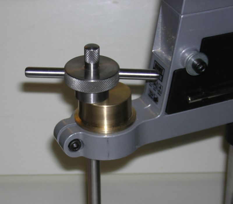
Now we add the knob-axle assembly:
As can be seen, the wings pass the head casting quite close, but it works well all the way up to M6/M8 .
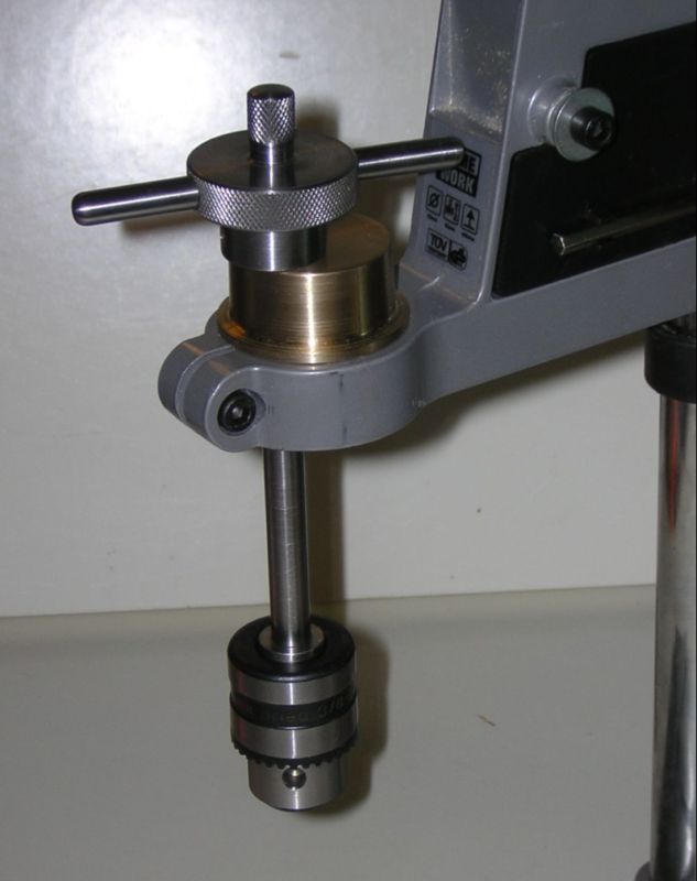
Time for the chuck.
It is enough to just screw on the chuck and tighten well, but for best performance the chuck is secured with a little Loctite or similar.
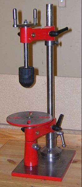
After some filing and finishing the whole stand is painted in your shops colour. The feeding function is locked by exchanging the guide-bar for an M10 bolt, and we get a result as shown below.
The black plastic cover is replaced and on its left side (invisible here) the chuck key gets a clip to be at hand when wanted, and out of the way when working.
This did not take long to make I would guess about a day or so and the result turned out to a useful addition the the workshop.
Best Regards
/PeterE
Peter E.


