Posted by John Haine on 29/03/2021 17:58:17:
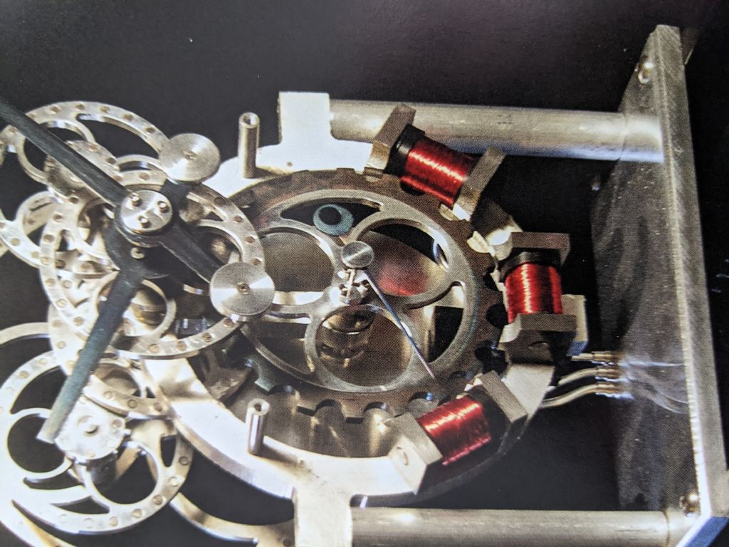
Nice! What is the diameter of the shaft please? It looks like about 2mm. Is the shaft silver steel?
I've ordered some of the magnets of the same size. I was wondering, if the shaft was the same nominal size as the hole, would it "short out" some or all of the flux? Can you tell if there is significant flux in the hole?
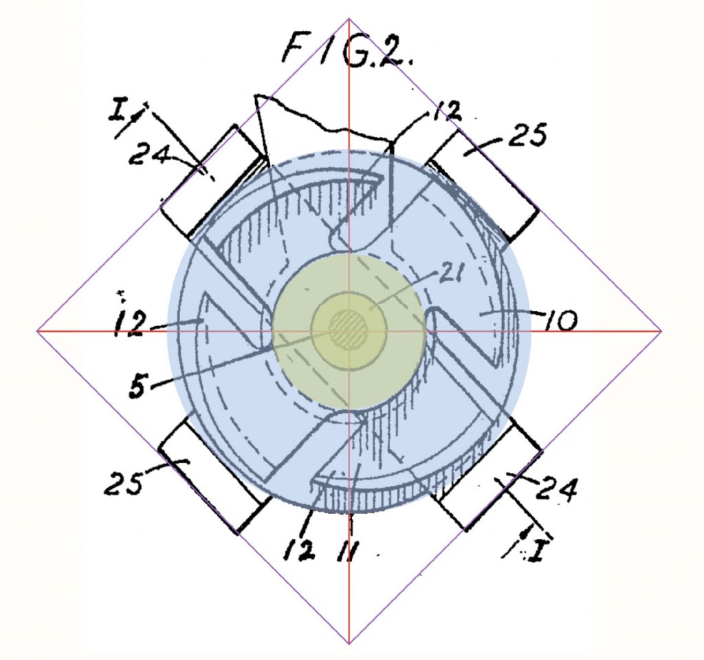
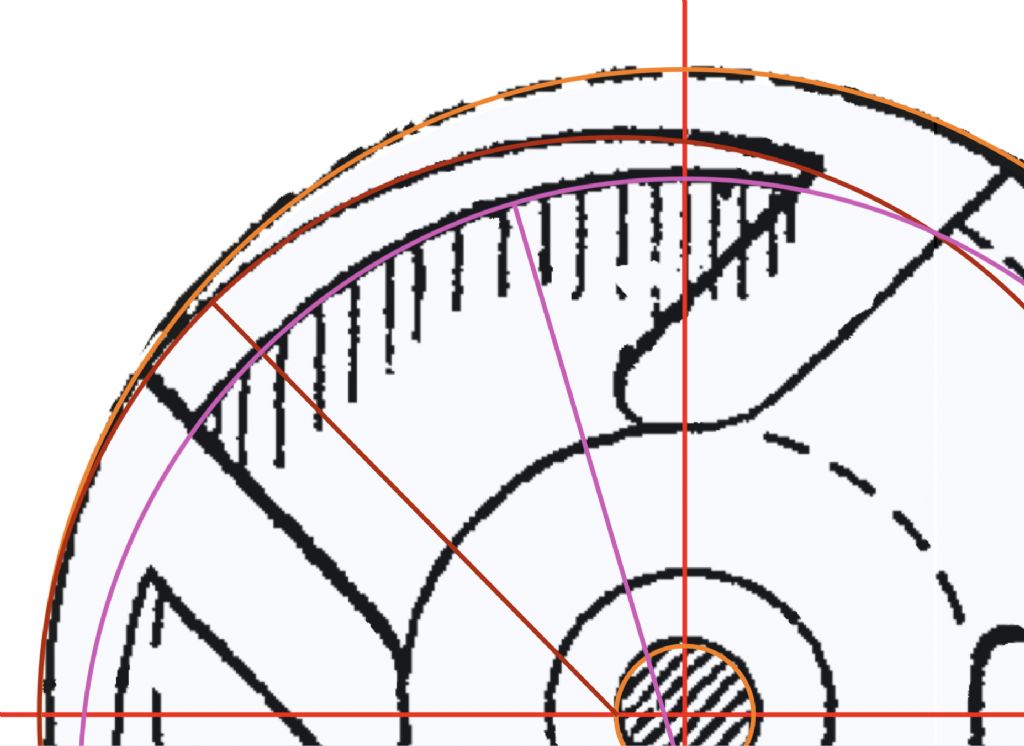
I'm thinking of trying the configuration where the stator is a solid strip, with a pair of "notches" in its periphery at 45 degrees, as in the wikipedia illustration (and patent I think).
How many turns on the coil? I've gone back to the coil winder project, have to get that working to make the coil.
Now where did I leave that bucket that needed mending.
The shaft is 1.5mm diameter and is the plain part of a 1.5mm twist drill. The bearings had an ID of 1.5mm and I happened to have a pack of cheap drills to hand so that was the obvious solution.
There is certainly some flux in the hole, but I suspect it wouldn't make much difference to the peripheral flux – might actually increase it. Worth some experimentation there.
I'm also considering the solid-strip-with-holes-at-45-degrees variant for the next (final) attempt as it is potentially easier to make.
The coil is 20mm long wound on a piece of 3/8" steel bar. The OD of the winding is a gnats less than 14mm but I couldn't tell you how many turns. The wire is 38 SWG. I'm planning to try a slightly different configuration for the magnet – I have 4 plastic sewing machine bobbins that I wound with rather thinner wire (50 SWG I believe) for another project that never completed; the bobbins are around 6mm ID. One or possibly two of those may be about right to drive a rather scaled down motor. We'll see.
Edited By Tony Jeffree on 29/03/2021 18:34:50
Brian Smith 1.


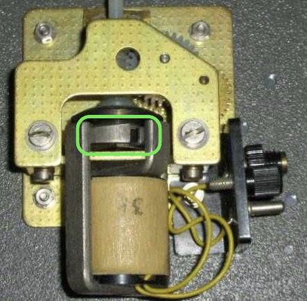

![img_3857[1].jpg img_3857[1].jpg](/wp-content/uploads/sites/4/images/member_albums/46229/891444.jpg)
![img_3856[1].jpg img_3856[1].jpg](/wp-content/uploads/sites/4/images/member_albums/46229/891443.jpg)
