The familiar formula for an ideal pendulum’s period is T=2*Pi*SQRT(L/g), where T is the period (the time it takes for one back-and-forth swing), L is the length of the pendulum, and g is the local acceleration due to gravity. Rearranging this formula thus allows for the measure of the local acceleration of gravity, g, on Earth.
But no physical pendulum is ideal, and so for a hundred years or more, scientists struggled to use pendulums to measure the local force of gravity. That was until 1817, when Captain Henry Kater created a reversible pendulum: one that can be hung with the heavy side down or the heavy side up. By adjusting the pendulum until the period was the same when hung either way, the distance between pivots was found to be equivalent to L in the ideal-pendulum formula, and an accurate calculation of the local acceleration of gravity on Earth, “g”, could finally be made. His pendulums, and ones like them, were used around the world up until the 1950’s to measure local force of gravity, and hence local geological features, to determine the shape of the Earth, to discover that the core of the Earth is iron, and so on.
This project attempts to create a precision reversible “gravity pendulum” as a learning exercise for machining basics and metrology, and just for the fun of recreating a historical scientific experiment.
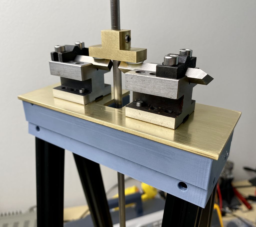
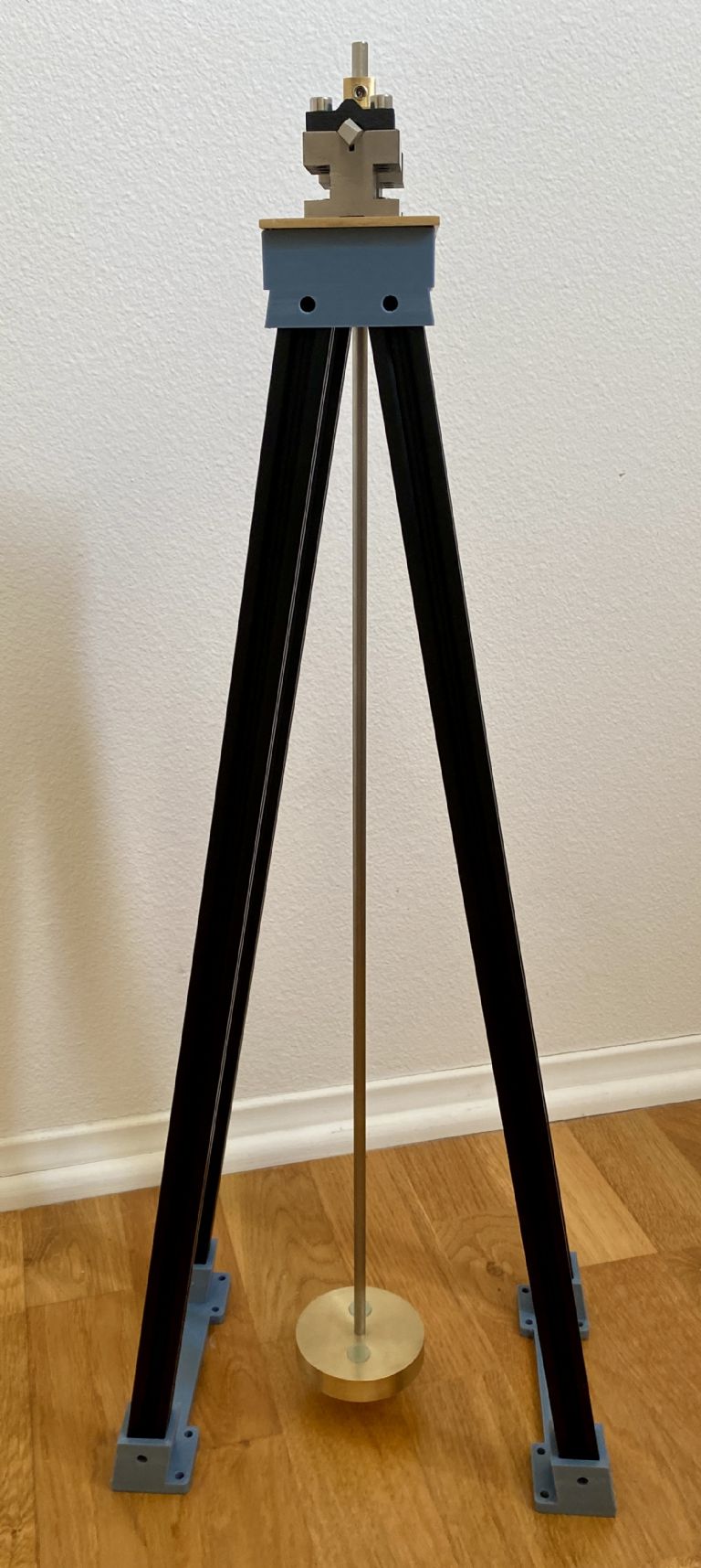
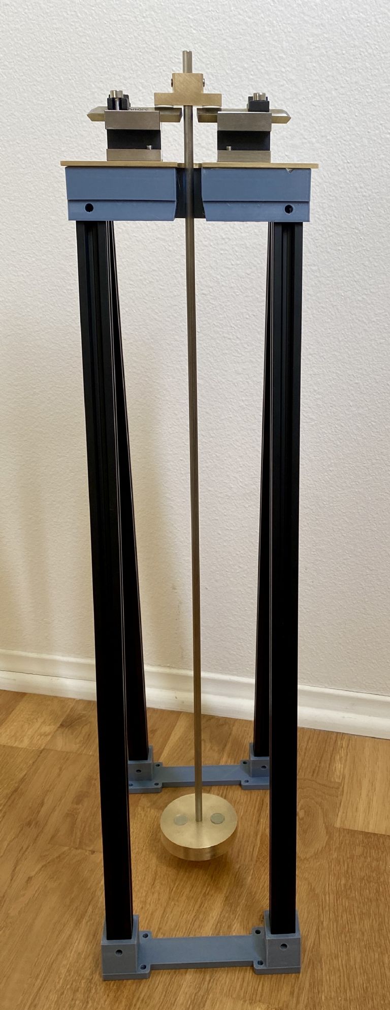
An introductory view of the pendulum on its support stage.
A drawing of Kater’s pendulum from 1817 is shown below (horizontally, without the mount), in front and side views (from Wikipedia). Object “d” is a heavy brass bob, objects “a” on the left and right are triangular knife edges used as pivots to balance the pendulum from either end, objects “e” are “flags” used to time the pendulum’s period, and objects “b,c” are adjustment weights incorporating a fine screw adjustment. The main shaft between the pivots “a” is also heavy brass, and about 2 meters long.
The triangular knife-edge pivots was made from “wootz” steel, and rocked on hard agate plates for low friction. This made the L measurement (the distance between the knife’s edges) practical and enabled the reversing function. The pendulum was swung freely, with no restoring force.
Kater measured the period of his pendulum by comparing it to the swing of a clock's pendulum (calibrated against the motion of stars) via a “method of coincidences.” If the two periods are slightly different, then watching for coincidences of the two allows a vernier-like measurement. So, for example, if the two swings exactly coincide once out of every hundred swings, then the two periods differ by (approximately) a part in 100.
Kater’s original measurement, made in London, was g=9.81158 m/s^2, though the claimed accuracy may have exceeded reality at least in the last digit. The error on his measurement of the length of the pendulum used in this calculation was purported to be no more than 7.1 micrometers (0.00028 inches); a fabulous feat for the time.
The pendulum’s shaft is made from 0.25” diameter Invar, an alloy of iron and nickel (generally 64% iron and 36% nickel). This material has an unusually-low coefficient of thermal expansion of about 1.2 ppm per degree C. This substantially reduces temperature effects on the precision of the measurements. The shaft is about 2’ long.
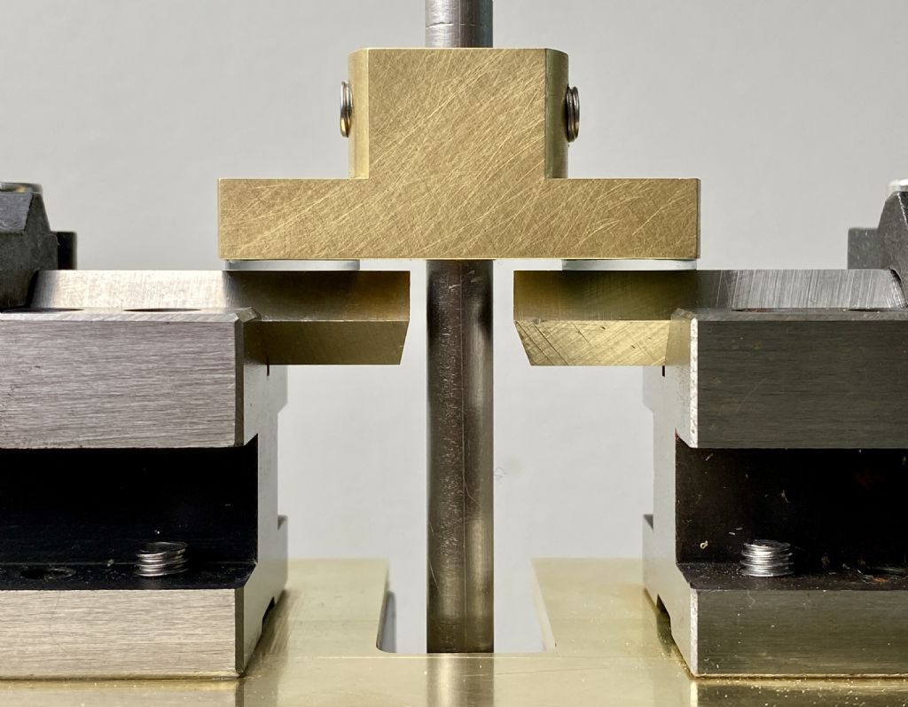
Kater placed the knives on the pendulum, which rode on agate plates on the pendulum’s platform. I reversed this, putting small sapphire disks on the pendulum and the knives on the platform. This means that the same set of knives is used either way the pendulum hangs, eliminating one source of error.
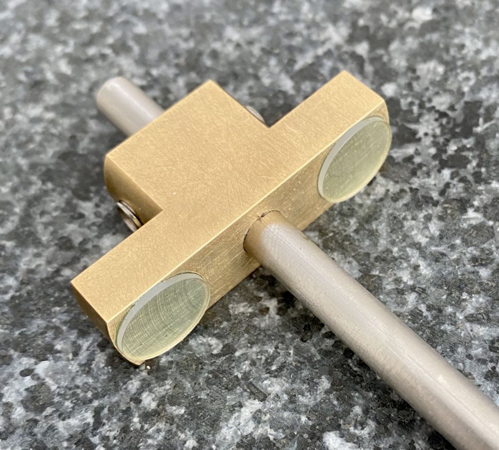
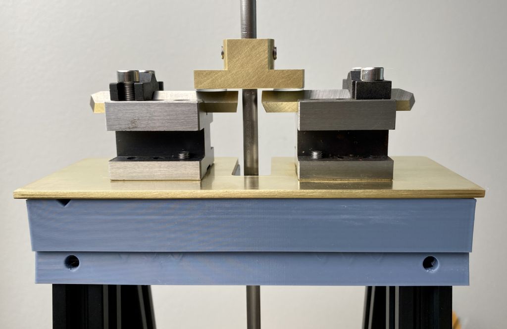
On the light side of the pendulum (the normal “up” side) is a small bar of brass that acts as the anvil on that side, resting on knife edges. It can be moved along the shaft and fixed in position using two brass-tipped set-screws. Moving its position is the primary way to adjust the period of the pendulum, i.e. by lengthening or shortening it.
Two 0.5” by 0.0394” sapphire windows were applied to the brass bar to act as “anvils.” Sapphire is far harder than steel, and can rest on steel knife blades without being marked. Pure sapphire is extremely clear, and the blue tinge seen is from the adhesive. The windows were selected to be the same thickness to well under 1 thousandth of an inch.
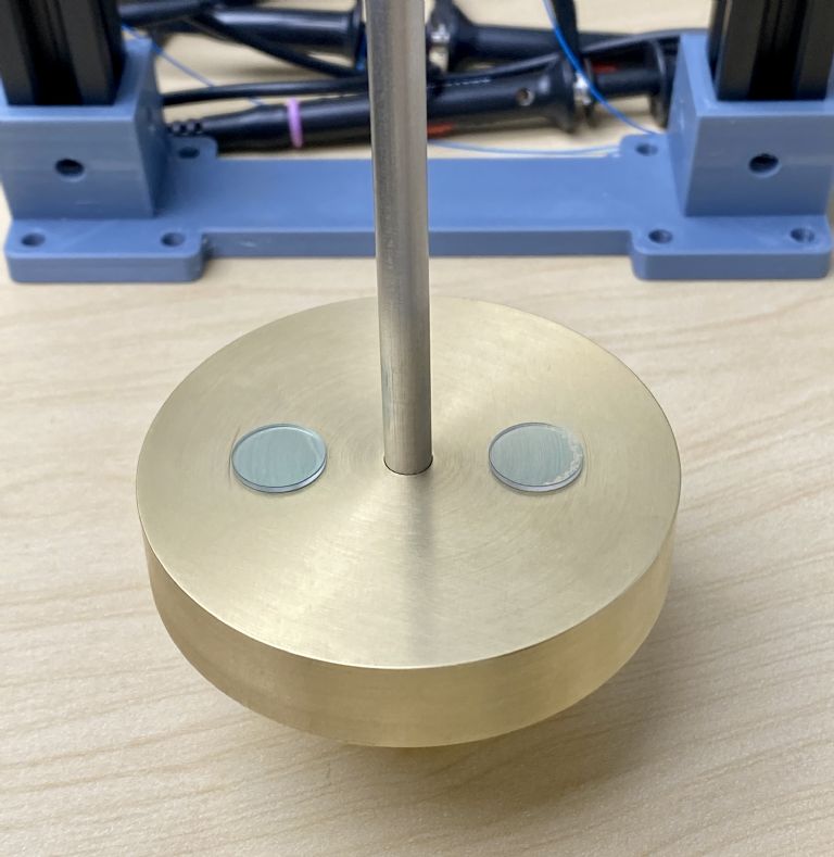
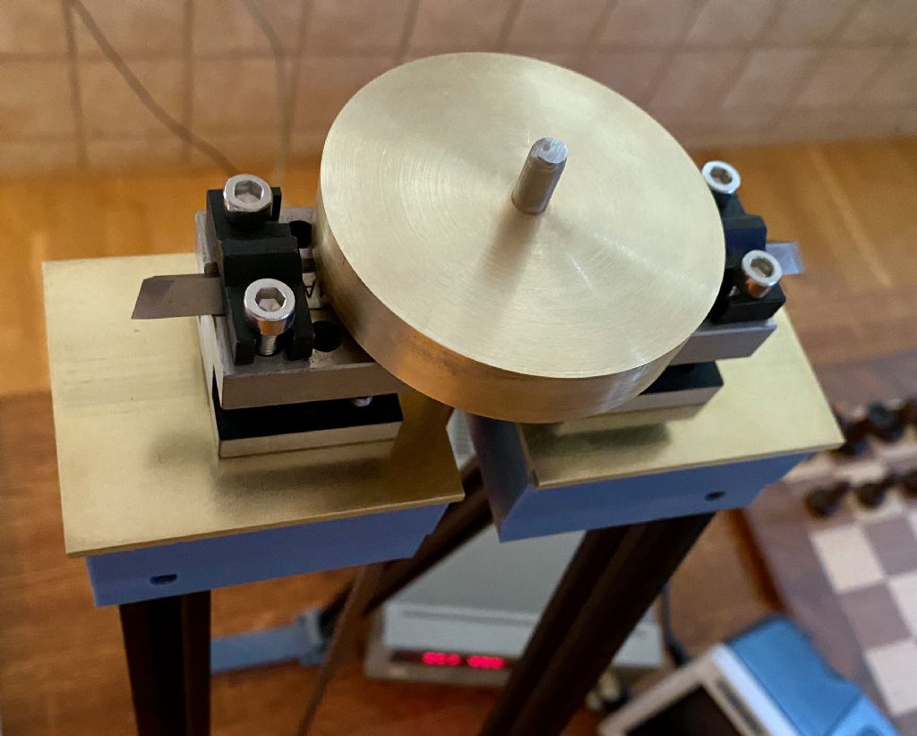
The bob is a brass disk of about 0.5 by 2.75 inches, and weighing about 1.5 lbs, fixed to the Invar shaft by a penetrating adhesive. The bob is hung with the disk parallel to the horizon rather than hanging vertically as normally seen in clock pendulums. This position centralizes and minimizes the spread of the weight over the length of the Invar rod that it’s attached to.
Having the mass close to the pivots is also important. If all mass was right at the pivots, the length of the pendulum would not need any adjustment – any length should have equal periods when hung either way. But if the heavy mass (especially) is at all distant from the heavy-side knives, then the light side’s mass and/or position has to be adjusted to compensate. So an orientation of the heavy bob as close to the knives as possible, as this configuration allows, has advantages. Having the bob oriented this way also provides a convenient platform – the bob itself – for balancing on knife-edges (again, as close to the mass as possible).
I noted that the adhesive was not quite applied as evenly on the bob side as I'd hoped (I only had one shot at it), but so far it doesn't seem to be an issue.
Being cut with square edges, this bob is not as aerodynamic as clock pendulums usually strive to be, but it allows an easy and accurate measurement of its dimensions. The Repsold/Bessel pendulum (an improvement over Kater’s design) also included a same-sized bob on the light end, e.g. made of aluminum instead of brass. Having equalized shapes on both sides of the pendulum nullifies differences in air friction when the pendulum is reversed. It’s my intention to eventually 3D print a light shell that can be fitted over the light-side anvils for this equalization.
The frame for the pendulum is a free-standing “A-frame” rather than wall mounted so that it can be moved. The “A” leans in towards the direction of the pendulum’s motion to provide better rigidity in that direction. It’s made of 600mm long 2020 aluminum profile. This is smaller than ideal (Kater’s original was more like 2m long), but it’s proportioned for the ~1.5 lb. bob weight and 0.25” shaft diameter that I have. The frame is tied together by 3-D printed joinery made of PETG plastic.
I’m still deciding on a base material and configuration. As it lacks any at all at the moment, the structure is not very stable, but is OK for preliminary measurements.
A 3D printed PETG platform was printed to hold the legs of the stand and provide a (hopefully) flat surface for mounting the knives. A brass stage was cut to rest on top of the plastic platform. Initially, I had intended to implement a leveling apparatus between the brass stage and the plastic platform. However, the brass was found to be a little too thin to avoid slight bending under force, and plastic platform was found to be quite flat anyway, so in the end I mounted the two together. I estimate the deviation from flatness of the combination to be at or below 0.001” across the 6.5”platform.
On the brass stage, I mounted two V-blocks to hold the knives, which are 0.25” square tool-steel lathe blanks. It’s critical that these two knives have their edges exactly aligned with each other. Basic alignment was made by bolting a precision-ground rod in the two V-blocks before bolting the V-blocks to the brass stage. After removing the rod, I estimate that the deviation from parallelism between the two knives amounted to under 0.04 degrees deflection from horizontal, due to a very slight curve in the plastic platform that was transferred to the brass. This deflection means that the knives may bite an edge of one or both of the sapphire anvils rather than ride flat. I should be able to shim some of this out too, but the current result actually appears quite OK for now. If I redid this, I’d use thicker, stiffer brass and float it above the plastic, e.g. on 3 points, rather than bolting it to it.
Below is an image of the pendulum when it's mounted "upside-down" in the pivots.
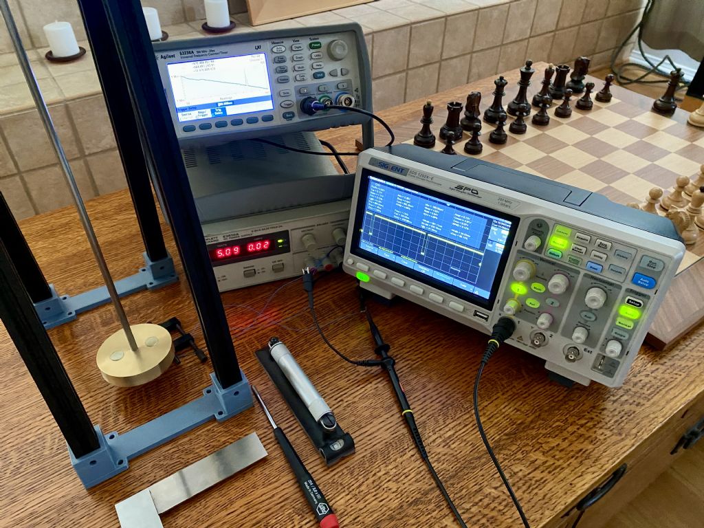
I purchased a few Sharp GP1A57HRJ00F opto-interrupters. I measure about a 20ns fall time, but a far longer rise time. I’d recommend only using the fall time when measuring time periods.
For now, I’ve borrowed an Agilent 53230A frequency counter to do period measurements. This instrument uses a 10 MHz internal clock for timing, which is likely much better resolution than Kater was able to achieve, and so the time resolution of period measurements should not be the limiting factor in the measurement of g.
Preliminary Period Measurements
The pendulum currently lacks an adjustment weight that would be used (as in Kater’s pendulum) to equalize the periods when hung in both directions. I intend to add a weight and adjust the periods as best as I can, but for now, here are the periods for arbitrary swing amplitudes:
Period for “normal” orientation (no adjustment weight): 1.528529 s.
Period for “reverse” orientation (no adjustment weight): 1.449025 s.
The noise in the period measurement (normal orientation): sigma = 8.9 us.
Signal/noise ratio for a single period measurement = 172,000
I initially rested my instruments on the same bench as the pendulum, and measured noise over 10 times worse. Moving them (and their fans) off the bench reduced noise substantially! I believe there is more to be gained here with some effort.
Measuring Q Factor
As there is no restoring force applied, I could measure Q by the simple technique of counting the number of oscillations before the swing is reduced to 1/e and multiplying by 2*Pi. I placed an engineer’s rule behind the pendulum and used my phone’s video camera to estimate the amplitudes of the swings. With 60 Hz frame rates, this appeared OK for about 0.5mm resolution.
Generally speaking, I’m reasonably happy with the pendulum and its platform so far, and early performance measurements – despite some sketchy details in how it’s set up right now – seem good.
The pendulum’s support needs a base to add mass and rigidity. It’s just sitting free on its legs for now, and is not terribly stable or even properly leveled. A proper base, leveled properly, should make a good difference.
I need to polish the knife edges (they are just stock tool steel blanks). This should reduce friction further.
I need to add an adjustment weight to the pendulum and make an effort to equalize the periods. This would allow a comparison between Kater’s classic method and Repsold/Bessels’s formula. I then need to find the center of gravity of the pendulum (after adjustment) as well as measuring the distance between the anvils and between each anvil and the COG.
I only have an engineer’s rule to do distance measurements. Early on, microscopes were used to measure the knife (or anvil) positions. Instead, I have experimented with using macro-photography to do pixel-level interpolation. This is not easy, but I’ll discuss that later.
Finally, I'll calculate g at my location, or possibly someplace where g is known to high precision.
On the question of the risetime of the optos, for different reasons I had a close look at the data sheet and discovered that there is a 15k internal pullup! Somewhere they show a test circuit with a quite low value pullup to get the spec risetime, and I use 470R pullups now. I will look again at the rise and fall times and as I now capture and store both edge times it's easy to use whichever is best.
Yes, I noted the internal pull-up resistor on the spec sheet, and the additional external one in their test schematic, too. I was happy enough with the ~20 ns fall time and didn't need both edges. Since adding another pull-up would likely worsen the fall time a little (while benefiting rise time), I left out the suggested external pull-up resistor.
And yes, placing the anvils on the pendulum was a lot easier than trying to fix knives to it!
Oh, no, another enchanting pendulum diversion, I could get sucked into this too. Get thee behind me Satan!
Two comments, if I may:
Grimthorpe emphasises the benefit of hanging pendulums rigidly from a massive stone wall, and mentions that nearby pendulums tend to synchronise. They're sensitive to vibration as John Haine found when he checked his clock's log after the Turkish/Syrian earthquake! Anyway, box frames are notorious for flexing. Worth trying, but any sway in the platform will reduce the accuracy to which 'g' is measured. To make sure the platform isn't moving, I'd test run the pendulum with a mirror on top, whilst bouncing a firmly fixed laser pointer beam off it back on to a distant wall. Angle the mirror amplify any movement; ideally the dot on the wall won't move at all. If it does, cross-brace the frame to reduce it. If that doesn't work well enough, an 'A' configuration is more stable than ▯.
The Agilent Frequency Counter may limit the accuracy of the measurement. The frequency counter's internal oscillator is either a 0.2ppm TCXO or an optional 10ppb OCXO. The instrument allows measurements to be taken quickly, but Kater got good accuracy by averaging multiple measurements, using a good pendulum clock calibrated with astronomical observations. His method was long-winded rather than inferior to modern electronics. I think the build quality of the pendulum has the potential to push the Agilent, especially if its the TCXO version and uncalibrated.
Whatever you do, don't tell me your address, I'm in serious danger of breaking the 10th Commandment:
“You shall not covet your neighbour's house; you shall not covet your neighbour's wife, nor his male servant, nor his female servant, nor his ox, nor his donkey, nor his Agilent 53230A Frequency Counter.”
I wanted a movable frame since I'd like to test it at a location where g is known to great accuracy. Otherwise, I can calculate g all day long and not have much clue as to whether it's anywhere near correct or not.
I constructed it in an "A" configuration to hopefully help stiffen it in the direction of swing. I haven't bolted the plastic to the aluminum profile yet (don't have enough T-nuts), but the fit is so tight that I don't think it would help anyway. I was thinking of adding braces connecting the sides of the A's, though, as the aluminum does "ring" a little if struck, and that can't be good. Obviously, it still needs a base quite badly, too.
That said, it's never going to be as rigid as optimal (optimal being a massive stone foundation wall in the basement of a remote castle), but the pendulum is fairly short and light, so with a few improvements I think it will do for now.
I don't believe the counter has the OCXO. I would expect it to be distinctly better than a plain Arduino, at least. But for the "g" measurement, I believe finding the center of gravity and the length measurements will inevitably be the limiting factors in accuracy.
Yes, it's very sensitive to the environment. My last test had lower noise for the period (6-ish us rms), just from less walking around it, and I think it should go lower still with care. I don't know what a "good" value for that is, though.
I wanted a movable frame since I'd like to test it at a location where g is known to great accuracy. Otherwise, I can calculate g all day long and not have much clue as to whether it's anywhere near correct or not.
…
May not be necessary to travel.
I don't understand the data, but gravitational data covering the whole of the UK can be downloaded from the British Geographical Society, scale approx 1 reading per 1.6sq km.
Easier to use at first glance is the Cement Kilns website which gives formula for calculating g by latitude and longitude, plus a long list of g values measured at Cement kilns around the country. My nearest is probably Westbury, Wiltshire g=9.8115. (Disgraceful, you'd think they'd change the factory to meet British Standard g which is 9.8118)
Anyone fancy building a rocket? NASA map g over the entire planet with a pair of satellites on the same orbit, one about 200km behind the other, and about 400km high. g is calculated by comparing sensor differences between the two as they overfly the surface. Couldn't find actual figures for g to count the decimal places, but if I read it right the error is equivalent to the mass of 30mm of water.
Not checked the Cement Kilns formula, and suspect the website has mangled it!
It does provide a (predicted?) error range, too. If I can match that within the error bars (I'm afraid that's unlikely), I'd be way more than satisfied! But one other possibility is to calibrate it to a specifically measured value, rather than a prediction, and then remeasure it locally. Just a thought, as I've got a way to go.
Edit: My understanding of the satellite data is that it was intended to provide a map at 20,000 ft above sea level, i.e. for air traffic, and that it doesn't necessarily provide highly accurate data at ground level. But I'll take a look at it again.
…one other possibility is to calibrate it to a specifically measured value, rather than a prediction, and then remeasure it locally.
…
That makes sense.
The BGS data is easier than I thought. For each of 115117 locations (lat and long), the column OBSERVED_GRAV gives a number that's added to 98000 to give g.
So, 51.692501N 0.02667E (somewhere in Essex) is 98000 + 1194.34milliGal, or 9.8119434 in real money. At school we were told to use 9.81 for proper calculations and 10 for rough work!
I wonder if the locations follow a pattern, perhaps public buildings, trig points, or maybe miles from anywhere to avoid vibration.
Can't wait to hear your first result. Not sure it's normal to be excited by such things!
Whoa! I wasn't expecting much, but for fun I made a quite rough measure of the COG and distances, and used my preliminary numbers from above (without equalizing the periods) and plugged it into the Repsold/Bessel formula.
I got g to within 0.026% of the predicted value. Not bad! 😀
Now to do a "proper" job of it!
Edit: The Repsold/Bessel innovation was to recognize that it's not strictly necessary to equalize the periods, as long as they are "close." This is because one term of their formula becomes quite small, leaving a term that only contains the two time periods, which I know extremely well. If, next, I can closely equalize them, then the problematic term (which requires measuring distances and the COG) becomes vanishingly small.
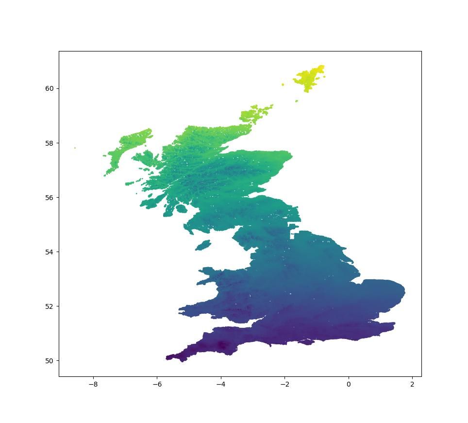
Just for fun, this scattergram plots g values by latitude and longitude from the BGS data. The g values are colour coded, showing gravity falls as one heads north:
Finding and measuring the COG accurately is difficult. The usual technique is to balance it on a knife-edge. However, given the asymmetry in the pendulum and how long it is, there's a range of a few mm over which balance is arguably achieved, and there's some guess-work involved in settling on a final position. Even marking that position accurately is tricky (I was thinking I need some markup fluid and just scratch the shaft on the knife). If anyone has ideas on how to find the COG of a very awkward item with more confidence, please let me know.
Anyway, I redid all the measurements "blind" (without looking at my previous measurements). The anvil-to-anvil measurement turned out to be identical, but the COG position differed by 0.01".
I'm now within 0.008% of the predicted value of g at my location. 😀
What's the value? As a check I can tell my scatter-gram to highlight all the points in the UK within 0.008% of it. Be interesting to see how much of the country lights up. Wonderful if only one dot comes on, and it marks your neighbourhood.