A Novel Free Pendulum Clock

Advert

A Novel Free Pendulum Clock

Home Forums Clocks and Scientific Instruments A Novel Free Pendulum Clock

Viewing 25 posts - 51 through 75 (of 79 total)
  • Author
    Posts
  • #534133
    Tony Jeffree
    Participant
      @tonyjeffree56510

      John, that seems to do the NTS thing, but nothing else – the one I mentioned earlier allows you to record measurements and will calculate day rates for you. There are a couple of other similar offerings that I am trying out: WatchCheck and Toolwatch.

      Advert
      #534328
      Tony Jeffree
      Participant
        @tonyjeffree56510

        More by luck than judgement, I seem to have adjusted the rate to less than a second a day already just by adjusting the rating nut.

        #534690
        Tony Jeffree
        Participant
          @tonyjeffree56510
          Posted by Neil Wyatt on 12/03/2021 11:12:43:

          Look out for the next MEW

          Neil

          That's a very pleasant surprise, Neil – I had almost given up on seeing that article appearing! Of course, in keeping with pandemic regulations, Skelly (as he is affectionately known) is now wearing a mask, but unfortunately, the ravages of salt water have now fused his bottom bracket, so he has been reduced to freewheeling. The unipivot is slowly boring its way through the top tube of the bike, so I fear it won't be long before he rests in pieces…

          #571358
          Andrew Cattell
          Participant
            @andrewcattell93655

            I went down this path some 20 years ago with a constant amplitude pendulum controlled by optical interrupters. I used two slotted opto devices, one to detect the extremity of swing at one side and a second one to detect the bottom dead centre. The interrupter obscurer is a single steel pin, just 1mm diameter poking down from the centre of the bottom of the pendulum shaft. The impulse is delivered by a hollow electro magnet coil mounted to one side of the pendulum shaft attracting a steel pin fixed to the side of the pendulum shaft just above the bob. The whole lot was masterminded by a small PIC microcontroller. The thinking is that if the interuptor pin fails to break the light beam at the extremity the impulse magnet will be energised for the next time that the centre opto is obscurred by the pin thus giving an accurately centred "pull" to the pendulum. The whole assembly of pendulum suspension, optos and impulse coil is mounted in the corner of a room, the suspension bracket is a short length of 1inch X 1inch angle iron bolted diagonally across the corner using 8mm masonry bolts. After setting it running the pendulum was brought to time by adding a few clothes pegs to the shaft above the impulse pin. The swing of the pendulum was compared with a signal from the NPL MSF time reference in Cumbria using a two beam storage oscilloscope. The impulse was made very small so that it would do 8 or nine impulses to to restore the amplitude which was then maintained for a few swings without impulse. This seemed to be better than giving a big pulse and missing many to my mind. Once I got it all trimmed I set about recording its operation, taking readings of time shift compared to 1 second tick from the MSF, the barometric pressure and the room temperature every hour. I did this for 14 days! I wanted to take enough readings to assess the effects of air pressure and temperature with a view to making compensation devices to be added to the pendulum later. By taking readings on the whole minute the MSF one minute pulse (easily itdentifable) and can be compared to the 30 second impulse sent to the display clock mechanism drifts of up to 2 seconds fast or slow can be taken with confidence that the right pulses are being compared. My post was deemed to be too long so more follows in next posting!

            Rans6……………………………

            #571359
            Andrew Cattell
            Participant
              @andrewcattell93655

              So far, so good. After a couple of weeks I stopped taking the readings every hour (it plays havoc with your sleep quality) but continued to record the readings once per day when we are at home. I noticed after a while that the time keeping was beginning to drift off. While investigating the errors I found that the pendulum had gone out of beat, the centre opto was not at the lowest point in the pendulum swing and the extremity opto, being the same distance from the centre opto, was controlling the amplitude to a lower constant size. I reset the position of the optos to restore the beat. Some months later I found that the timekeeping was slipping off the other way and sure enough the pendulum was out of beat the other way and the amplitude of swing had increased. It turns out that the whole house moves on a cyclic basis with the seasons, probably due to it being built on very high clay content ground, the moisture content of the clay changes through the year as the rainfall varies. Unbelievable. Just when you think you have removed or allowed for all of the things that might affect your clock something else comes to surprise you.

              Rans6…………………………..

              #571360
              Andrew Cattell
              Participant
                @andrewcattell93655

                I have yet to work around the issues of the house walls tilting with the seasons, to implement temperature and pressure compensation but the clock continues to run. I will change the software so that it monitors the time between consecutive passes of the centre opto breaks to allow detection of the out of beat-ness. I have enough spare pins on the PIC controller to allow it to drive a small stepper motor which will be used to "motor" a carriage with the two opto devices along a path in parallel with the direction of the tilt of the walls. This is not exactly in parallel with the swing direction of the pendulum so needs a bit of thought. When the house moves the pin on the pendulum gets dangerously close to one side of the slot in the extremity opto due to the movement hence the need to move the correction carriage on a non parallel track. The impulse coil has enough space around the pin that it will not drag due to the house tilt. This big air gap was a conscious design feature to minimise pneumatic drag as the pin enters and leaves the hole.

                The PIC controller is supplied from a wall wart psu and has a rechargeable battery backup which I built in at the beginning using some old NiCad cells found in my junk box. This battery has maintained the clock through a number of mains power outages, some lasting many hours. It also sends an impulse to an old factory repeater clock every 30 seconds so the time is on display, the display clock has its own battery which has also survived the power cuts so it has only needed attention twice a year when the clocks change.

                Rans6………………………………………

                #571361
                Andrew Cattell
                Participant
                  @andrewcattell93655

                  Other improvements I want to make.

                  At the moment the optos LEDs are strobed by the PIC micro to reduce power consumption and increase service life. They are only strobing for a few milliseconds before during and after the time when there is predicted to be a pin passing through. The strobing causes there to be a few 10s of microseconds jitter in the detection time of breaking of the beam when seen by the PIC. This might have some effect on the accuracy of the extremity position on boarderline cases of detect/not detect. It also affects the accuracy of the BDC impulse. Both of these can be made better by using some hard wired logic gates between the opto and the PIC, putting the PIC in control of when the optos are on and when the impulse needs to be on but letting the logic gates actually drive the impulse.

                  As others have noticed the slotted opts are affected by ambient light levels. I have done my best to shield them but as the pendulum assembly still has no case around it more can be done. What I am not sure about is whether the optos are showing any sign of sensitivity change due to aging. Thinking about how to detect/compensate for this.

                  I also want to investigate if the performance of the opto devices changes enough with temperature to give a measureable change in the pendulum accuracy.
                  =================================================================================================================================
                  The radio receiver I use to pick up the MSF time signals suffers from significant jitter, I think this is caused by the action of its built in AGC (automatic gain control) struggling to accurately lock to the transmissions. The MSF signal is fairly weak and at only 60kHz is badly affected by much of the electronic equipment operating within the house. TVs and computer monitors used to have display scan rates of this order and no doubt other stuff around also does. I have an oven controlled crystal oscillator salvaged from some mobile phone network equipment which I want to set up and trim to lock to the MSF signal, using a feedback signal derived from averaging the error between the divided crystal output and MSF pulses. If the averaging is over enough pulses the crystal should end up giving me a much more precise time pulse on a second by second basis than the jittery MSF signal does.

                  After all of the work I did (and have yet to do) on my clock I came across a design that has taken the subject to a whole new level. See the work of Edward T. Hall and the Littlemore Clock, your favourite search engine will find it.

                  Rans6……………

                  #571393
                  Michael Gilligan
                  Participant
                    @michaelgilligan61133

                    A great [group of 4] first posting, Andrew … Thanks yes

                    MichaelG.

                    #571400
                    Tony Jeffree
                    Participant
                      @tonyjeffree56510

                      Great posts Andrew!

                      Just a thought, but you could potentially fix the "house drift" problem by mounting the whole clock on gimbals. You would of course need to add sufficient viscous damping to the gimbal bearings and/or add mass to the structure so the pendulum oscillations themselves don't cause the whole contraption to swing, but it could be done.

                      #571402
                      Tony Jeffree
                      Participant
                        @tonyjeffree56510
                        Posted by Neil Wyatt on 12/03/2021 11:12:43:

                        Look out for the next MEW

                        Neil

                        Talking of which Neil…do you have an ETA for my most recent scribblings…?

                        #571408
                        John Haine
                        Participant
                          @johnhaine32865

                          Good work Andrew. Reading your last post reminded me that I believe that Hall was ultimately disappointed in the performance of his clock and attributed it to ground motion induced by a large nearby tree swaying in the wind.

                          On the issue of optos being sensitive to stray light, I think I referred earlier to Doug Bateman's clock. This was designed long before slotted optos were available so he had to roll his own. The clock uses a single sensor driven by a vane on the rod just above the rod, with a central slot to drive the impulse. So the sensor is hidden from the light source, the vane providing "shading". Likewise the amplitude is sensed by the end of the vane. There's some discrete logic to decide what to do with the sensed signals. Doug reported that there is no discernible sensitivity to stray light, I think because of the shading the vane provides, so any ambient light just adds to the illumination from the LED. His clock has been running since the 1970s I think so no problem with diminishing sensitivity.

                          Disciplining an oscillator to MSF or GPS is quite complicated. For the purpose of monitoring cycle-by-cycle variations it could be better to just use the TCXO signal "unvarnished" and if necessary calibrate it? When I was monitoring my "Arduinome" I used a "picPET" to time the opto edges using a 10MHz OCXO, logging the results wing-by-swing in an R-Pi. From this I periodically uploaded the data over Wi-Fi. I had two problems with this – one was that the Pi took too much current to be able to run it from the backup so a run would stop if there was a brown-out or power cut. Also the Pi would very occasionally lose Wi-Fi connectivity, which needed restarting to fix, again interrupting the run. This is a know Pi problem and though there is a fix even that didn't seem entirely reliable. In the end though the pendulum didn't have the short-term stability to make detailed monitoring worthwhile, and the clock keeps good enough time given it doesn't have a seconds hand (uses a modified Synchronome movement).

                          #571411
                          Andrew Cattell
                          Participant
                            @andrewcattell93655

                            Thanks for the suggestion Tony J,

                            There might be some merit in mounting the whole clock on gimbals even though it goes against the grain, robust and solid "feels" like the right approach to gaining stability. Having an assembly balanced by gravity and then impulsing one part of it against the other seems to be asking for another set of motion variables to interfere with the system.

                            I have thought about mounting the opto sensors all on a static pendulum pivoted on the same axis as the moving pendulum and damped to stop it swinging in sympathy. What slowed me down at that point was dealing with the tension in the wires causing the static pendulum to hang off centre. I then came up with a complicated arrangement which put the sensors on a fixed bracket but used mirrors on the static pendulum to get the light beams all across the path of the obscuring pin. Beam divergence reared its ugly head and then laser diodes looked promising……………

                            Option paralysis and life have prevented any further work..

                            Rans6…………………

                            #571416
                            Michael Gilligan
                            Participant
                              @michaelgilligan61133

                              I was chatting with Jim Arnfield, onFriday … and he mentioned his latest [and apparently successful] Opto configuration on his double pendulum clock: He is putting each sensor at the end of a long thin tube, blackened internally.

                              Seems like a very good idea to me enlightened

                              MichaelG.

                              #571418
                              Tony Jeffree
                              Participant
                                @tonyjeffree56510
                                Posted by Michael Gilligan on 15/11/2021 12:10:30:

                                I was chatting with Jim Arnfield, onFriday … and he mentioned his latest [and apparently successful] Opto configuration on his double pendulum clock: He is putting each sensor at the end of a long thin tube, blackened internally.

                                Seems like a very good idea to me enlightened

                                MichaelG.

                                Great idea.

                                #571424
                                Andrew Cattell
                                Participant
                                  @andrewcattell93655

                                  I just had another watch of the video in the OP of this thread. The first thing that struck me is the size of the pendulum swing. My understanding is that a large swing is asking for trouble with circular error which may or may not be significant with a tightly controlled amplitude. It does, however increase the amount of energy the system is losing to air resistance. In my clock the pendulum is 60cm long (3/4 second) and the swing is controlled to plus or minus the closest distance that 2 slotted opto devices can be mounted, approx 6mm between BDC and peak. This gives an angle of swing of less than 1 degree each way from the centre.

                                  Rans6……………….

                                  #571432
                                  John Haine
                                  Participant
                                    @johnhaine32865

                                    Ah well, that's a perennial debate! Circular "error" is only an issue if the amplitude changes – and if it does then it may change the escapement error too. Circular deviation can be used to advantage to nullify the effects of barometric pressure as noted above. In "Clock B" the amplitude is over 6 degrees! In Doug Bateman's clock amplitude varies by only ~1 second of arc with an amplitude of 1.3 degrees.

                                    In practice the energy lost by the pendulum to air resistance is probably a fraction of that lost to running the opto LEDs and the processor. There is a school of thought that says a high energy throughput makes a clock more accurate though without much scientific justification. I do believe though that a high amplitude is beneficial as it maximises the "signal to noise ratio".

                                    #571445
                                    Tony Jeffree
                                    Participant
                                      @tonyjeffree56510

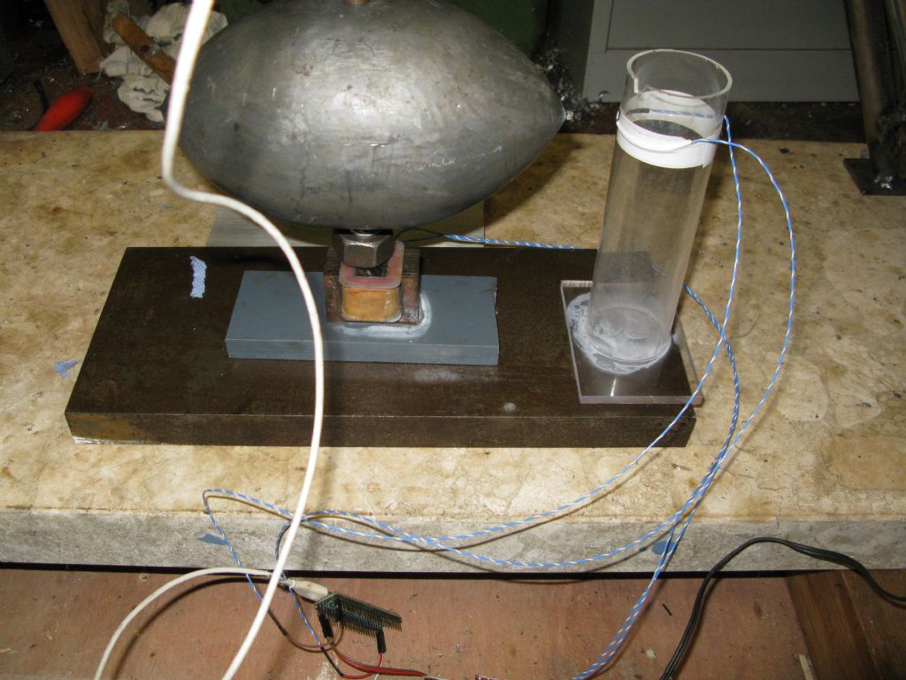
                                      I make no claims about how well or badly my clock performs – my intent was to build a pendulum that operated with no direct mechanical contact and the minimum of indirect mechanical interference, and to that end, I have succeeded. As it is currently set up, the clock runs for ~100 seconds between impulses; that interval, and also the choice of arc of swing, can be adjusted to tase by re-positioning the Hall effect sensors, changing the distance between the electromagnet and the pendulum bob, and changing the electromagnet current. With a sifficient supply of round tuits I'm sure all of the potential permutations could be investigated, along with their effect on the clock performance.

                                      However, as John has observed, as the arc of swing is closely controlled, circular error shouldn't itself be a major problem.

                                      #572058
                                      Bob McDougall
                                      Participant
                                        @bobmcdougall63250

                                        18 years ago, i read Accurate Clock Pendulums , published 2004 after listening to a R4 book review, of course.

                                        Shortt are out of my price range, Enthused I made an oak 2 part mould for a bi-linear bob cast in type metal also from Keighley 11Kg bob, split the mould, not enough weight and got it cast at metcalfes in Keighley. Bought quartz pendulums 2 , ground a recess in each end to hold a split washer. everything made from ironless aluminium bronze. 3/4 inch steel pendulum head platform with dual single piece suspension springs

                                        I cracked the first pendulum attaching the bob , the spare was broken in a move.

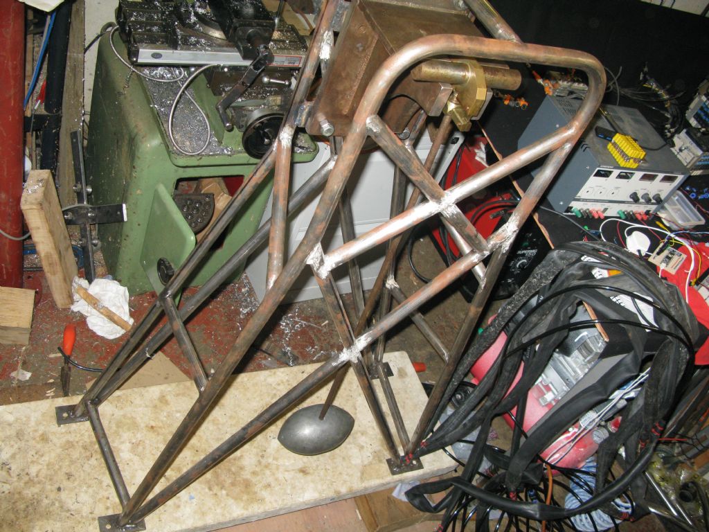
                                        2021 got a JD2 tube bender for another project and ended up building a frame for the top pivot , Ive got a steel pendulum rod as a place keeper, .

                                        Q 100K ~ 300K , thats what I measured i16 ? years ago with the top assembly bolted to a cellar wall

                                        Just seen this thread , thanks for posting. I will read it all tomorrow. .

                                        I'll post some pics , looks like we have a common appreciation of something that is (almost)? undefinable. Time

                                        do you have a siesmometer.

                                        #572209
                                        Bob McDougall
                                        Participant
                                          @bobmcdougall63250

                                          So I put my pendulum together with a electromagnet, teensy 4.1 . a reed relay with a magnet on the bob to time the fet coil power from 12V . It went so well the pendulum smashed into the glass reed relay and smashed it,reed switch self destructiontube steel frame

                                          #631894
                                          Tony Jeffree
                                          Participant
                                            @tonyjeffree56510

                                            I've just acquired a copy of "Harrison Decoded" which makes very interesting reading. Given that electronically impulsed clocks have rather fewer issues to deal with than there are with "Clock B" (no mechanical escapement, no issues with going trains and friction…etc), it ought to be entirely possible to achieve comparable performance to "Clock B" with an electronically impulsed free pendulum swinging in a "normal" environment (i.e., not temperature/pressure/humidity controlled). Has it been done?

                                            #632008
                                            S K
                                            Participant
                                              @sk20060

                                              Harrison's Clock B was recently tested and found to be accurate to 1 second over a 100 day period. That's 0.1 ppm!

                                              The COSC standard for quartz "chronometers" is +/- 25.55 seconds per year, which is much worse. (Whether "COSC" certification is meaningful here is debatable, but it's a point of reference.)

                                              Excellent and somewhat-pricey temperature-compensated oscillators are also about 0.1 ppm.

                                              So Harrison's design (actually made by Burgess) beat quartz movements by a mile and achieved parity with modern oscillators with electronic compensation. Sounds like it would be hard to match, even with the advantages of an optically monitored and electromagnetically driven free pendulum, but it's a fun target.

                                              So who will be the first!? (Not me, my work-in-progress will be too small and light to compete.)

                                              Edited By S K on 04/02/2023 15:37:34

                                              #632018
                                              SillyOldDuffer
                                              Moderator
                                                @sillyoldduffer
                                                Posted by S K on 04/02/2023 15:26:12:

                                                Harrison's Clock B was recently tested and found to be accurate to 1 second over a 100 day period. That's 0.1 ppm!

                                                The COSC standard for quartz "chronometers" is +/- 25.55 seconds per year, which is much worse. (Whether "COSC" certification is meaningful here is debatable, but it's a point of reference.)

                                                Excellent and somewhat-pricey temperature-compensated oscillators are also about 0.1 ppm.

                                                So Harrison's design (actually made by Burgess) beat quartz movements by a mile and achieved parity with modern oscillators with electronic compensation. Sounds like it would be hard to match, even with the advantages of an optically monitored and electromagnetically driven free pendulum, but it's a fun target.

                                                So who will be the first!? (Not me, my work-in-progress will be too small and light to compete.)

                                                It's a good target to aspire to and I'd be very pleased to get performance half that good.

                                                Strictly speaking, the performance wasn't achieved by Harrison's Clock B, because he never made one! Rather it was delivered by a clock built on Harrison's principles. The build was started by Mr Burgess who completed Clock A in 1987, but didn't finish Clock B. 30 years later the parts were bought in 2009 by a collector who had the clock finished by Charles Frodsham & Co. I share their pain – my clock project is also taking years, with no end in sight!

                                                The Burgess/Frodsham clock uses technology not available to Harrison, like Polyaryletheretherketone pallets. Whether Harrison, who was a genius, could have got the same performance in his lifetime is questionable, but I'm sure it would have been brilliant.

                                                Does anyone have any details on Clock B, such as how it compensates for changing air-pressure? Although the effect is small my crude pendulum responds to it, and it's nowhere near 0.1ppm

                                                Dave

                                                #632019
                                                John Haine
                                                Participant
                                                  @johnhaine32865

                                                  The key aspect of Clock B is that the pendulum automatically compensates for barometric pressure variation by balancing the variation in rate caused by buoyancy against the opposite change in rate caused by amplitude change resulting from varying air drag. It is of course temperature compensated by using an invar pendulum rod and by other means. It's a complex system that is very hard to "design" as not all aspects of it can be modelled but have to be set up on test.

                                                  Any pendulum that is allowed to vary its amplitude according to air drag has a nominal amplitude where it has zero first-order sensitivity to air density variations. So it would be possible to apply the same method as Clock B does, though with much less complication.

                                                  #632021
                                                  John Haine
                                                  Participant
                                                    @johnhaine32865

                                                    Dave, I sent you a PM.

                                                    #632024
                                                    Martin Kyte
                                                    Participant
                                                      @martinkyte99762

                                                      From my understanding of Harrison's techniques was that he recognised that atmospheric conditions were connected. That there was a correlation between density, air pressure, temperature etc. His answer was to use circular error to compensate for the changes. On the RAS clock he fitted cheeks either side of the pendulum suspension so as amplitude increased so the effective length of the pendulum was lessened. Rather than have this as perfect amplitude compensation only, he over compensated to allow for the variation in pressure essentially allowing one effect to work against another. The brocklesby Park clock pendulum has evedence of a vane on the back to increase drag which has been suggested that Harrison was aware of these effects at a very early stage and did do some experiments. Compensation on the RAS could really be only done by patient running, measurement and adjustment untill things were brought in balance.

                                                      regards Martin

                                                    Viewing 25 posts - 51 through 75 (of 79 total)
                                                    • Please log in to reply to this topic. Registering is free and easy using the links on the menu at the top of this page.

                                                    Advert

                                                    Latest Replies

                                                    Viewing 25 topics - 1 through 25 (of 25 total)
                                                    Viewing 25 topics - 1 through 25 (of 25 total)

                                                    View full reply list.

                                                    Advert

                                                    Newsletter Sign-up