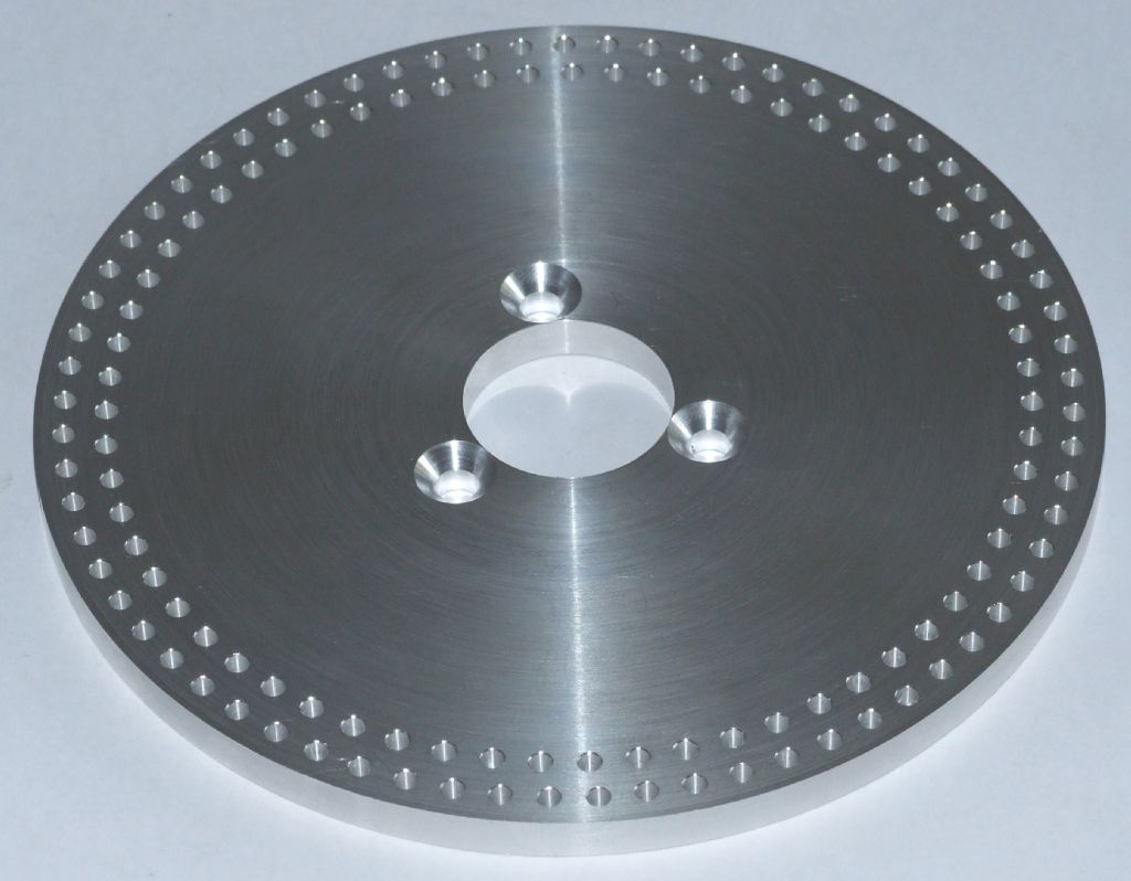
A New Dividing Plate for my Dividing Head
A New Dividing Plate for my Dividing Head
- This topic has 40 replies, 17 voices, and was last updated 19 March 2015 at 18:07 by
 Dave Martin.


- Please log in to reply to this topic. Registering is free and easy using the links on the menu at the top of this page.
Latest Replies
-
- Topic
- Voices
- Last Post
-
-
Sieg KX3 spindle motor replacement/upgrade
Started by:
Beardy Mike
in: CNC machines, Home builds, Conversions, ELS, automation, software, etc tools
- 6
-
10 February 2025 at 19:20
Beardy Mike
-
Metal stock
Started by:
daisytwoduffs
in: Beginners questions
- 16
-
10 February 2025 at 18:35
Hollowpoint
-
Taylor Hobson cutter grinder modificaton
1
2
Started by:
David George 1
in: Workshop Tools and Tooling
- 9
-
10 February 2025 at 18:32
Bazyle
-
Family tree prog
Started by:
JimmieS
in: The Tea Room
- 14
-
10 February 2025 at 17:07
Nicholas Farr
-
How to identify a thread, ACME vs TR
1
2
Started by:
moonman
in: Beginners questions
- 18
-
10 February 2025 at 16:51
JasonB
-
indexing head lathe
Started by:
Danni Burns
in: Manual machine tools
- 10
-
10 February 2025 at 16:43
bernard towers
-
LBSC Dot/Diana Cylinder Castings
Started by:
Roger Hahn
in: Materials
- 5
-
10 February 2025 at 16:19
Nicholas Farr
-
Can a metric baby do imperial?
Started by:
beeza650
in: Beginners questions
- 12
-
10 February 2025 at 16:15
peak4
-
Calling all Little John and other Raglan users
Started by:
David Senior
in: General Questions
- 4
-
10 February 2025 at 15:50
David Senior
-
Vickers Inverted Engine
1
2
Started by:
JasonB
in: Stationary engines
- 9
-
10 February 2025 at 11:56
JasonB
-
Hemingway Kits
Started by:
James Hall 3
in: General Questions
- 11
-
10 February 2025 at 11:03
JasonB
-
CA glue and magnetism
Started by:
Bill Phinn
in: General Questions
- 12
-
10 February 2025 at 10:46
bernard towers
-
Pre-war Italian thread ?
Started by:
Tim Stevens
in: Help and Assistance! (Offered or Wanted)
- 7
-
10 February 2025 at 10:29
noel shelley
-
More Lidl questions
Started by:
old mart
in: Hints And Tips for model engineers
- 9
-
10 February 2025 at 08:37
SillyOldDuffer
-
Pennsylvania A3 Switcher
1
2
3
Started by:
Mark Elen 1
in: Work In Progress and completed items
- 18
-
9 February 2025 at 22:02
Mark Elen 1
-
Cheap but useful Multimeter
Started by:
Danni Burns
in: Electronics in the Workshop
- 8
-
9 February 2025 at 18:39
Danni Burns
-
Electric Car Battery Retention
1
2
Started by:
Vic
in: The Tea Room
- 18
-
9 February 2025 at 17:39
old mart
-
What Do These Mean; Why So Many Loop Errors? (Alibre Atom)
Started by:
Nigel Graham 2
in: CAD – Technical drawing & design
- 7
-
9 February 2025 at 17:15
SillyOldDuffer
-
Building Wilding’s Tower Clock
Started by:
Chris Raynerd 2
in: Clocks and Scientific Instruments
- 7
-
9 February 2025 at 16:34
Chris Raynerd 2
-
Drilling feed rates
Started by:
Beardy Mike
in: CNC machines, Home builds, Conversions, ELS, automation, software, etc tools
- 5
-
9 February 2025 at 10:51
Beardy Mike
-
Slow to load
1
2
Started by:
Diogenes
in: Website Questions, Comments, and Suggestions
- 17
-
9 February 2025 at 09:05
Dell
-
3D Touch Probe, Sieg KX3 & Mach3
Started by:
Matt Harrington
in: CNC machines, Home builds, Conversions, ELS, automation, software, etc tools
- 3
-
8 February 2025 at 23:36
Matt Harrington
-
A New Scam Format?
Started by:
Nigel Graham 2
in: The Tea Room
- 6
-
8 February 2025 at 20:17
Nigel Graham 2
-
building a parting tool
Started by:
celso ari schlichting
in: General Questions
- 3
-
8 February 2025 at 17:43
Grizzly bear
-
How to gain access to The Railway Magazine Index
Started by:
Greensands
in: The Tea Room
- 1
-
8 February 2025 at 17:18
Greensands
-
Sieg KX3 spindle motor replacement/upgrade
Latest Issues


Newsletter Sign-up
Latest Replies
- Sieg KX3 spindle motor replacement/upgrade
- Metal stock
- Taylor Hobson cutter grinder modificaton
- Family tree prog
- How to identify a thread, ACME vs TR
- indexing head lathe
- LBSC Dot/Diana Cylinder Castings
- Can a metric baby do imperial?
- Calling all Little John and other Raglan users
- Vickers Inverted Engine

