Nice work Tug – most impressive construction for the cylinders. Not only have you made the lot look like a real casting, but I am sure the JB Weld used will hold well and is a good construction material. I know you want to run the engine only on air, so heat doesn't come into it, but even on steam I fell sure JB Weld would be good.
I would hazard a guess that most model engineers, running this engine on steam, would only use steam at about 150psi max; (though probably a bit less, 100-125 psi maybe, maybe as low as 80psi) at 150psi the saturated steam temp is only around 350ish deg.F, (358 to be pedantic at 150psi!). Given that the Original JB Weld is able to withstand 550 deg.F and even at 200 psi the saturated steam temp is only about 380deg.F, so there is a fair degree of leeway in there temp-wise, even allowing for a fair degree of superheat, so yes, technique used is good to go!
Know what you mean about garden work, on the case myself, but looking forward to your next instalment whenever that is.
Jason – Strange you should mention the soft jaws as after extensive use since modifying them, one jaw has finally 'given' very slightly. The amount of work done however certainly made it worthwhile exercise and I shall remill and fit new pieces in the same way for more extended useage. I think I will put a small pin in this time to resist the radial pressure on the JB Weld which appears to be the reason for the slight movement.
Chris – as said I do only intend to run this on air but I agree with all that you say with regard to using steam. My thoughts that it would withstand any forces under steam are based on the same conclusions as yourself. The likelyhood of running this on anything greater than 80-100psi is minimal at best so the JB will stand up to that with a good safety margin if done properly.
Some time back I did a test piece with three flanges identical to the parts intended for the job itself. Just JB'd into respective bores – no other means of retention – and left for a few days to fully cure. I pressure tested it to 300psi for a good 20-30 mins without any loss of pressure then repeated it at the same pressure but this time with the part under constantly boiling water for the same period.
That may possibly be of interest to a wider audience so I'll make a new post on it.
Tug – you mentioned two phases in your last post that I missed when I commented on using JB Weld – "if done properly" and "fully cure". They are the important bits!
Hi Guys, after far too long an 'aeromodelling distraction', pleasurable as that has been, I finally have set some time aside to progress this engine a bit more.
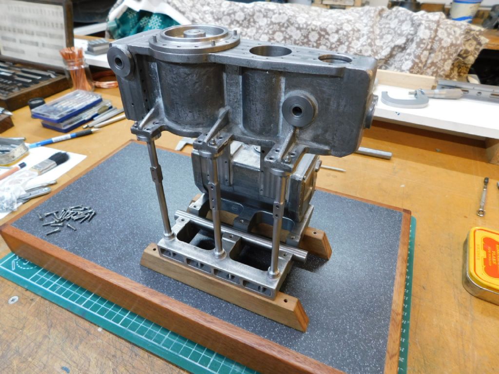
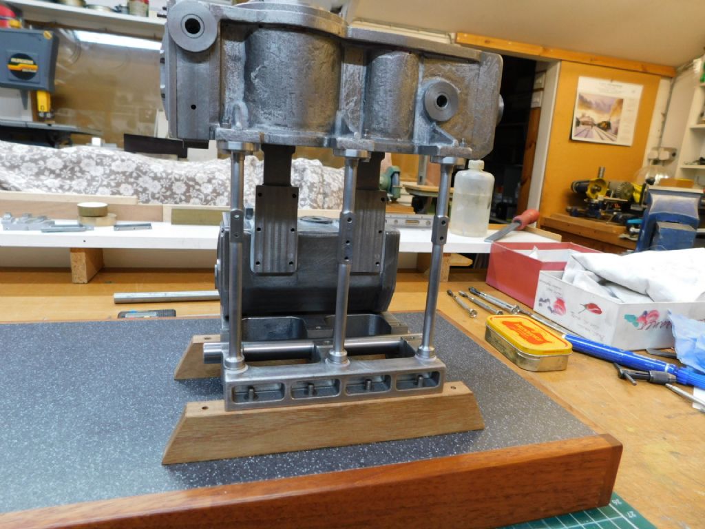
Began by setting up a base and making a couple of bearers from mild steel (just behind the mic on the shelf behind) but these didn't look right for some reason so decided to use hardwood instead.
With the front columns made it was possible to see if it all lined up – pleased to say it did as there is a lot of holes that have to be in the right place.
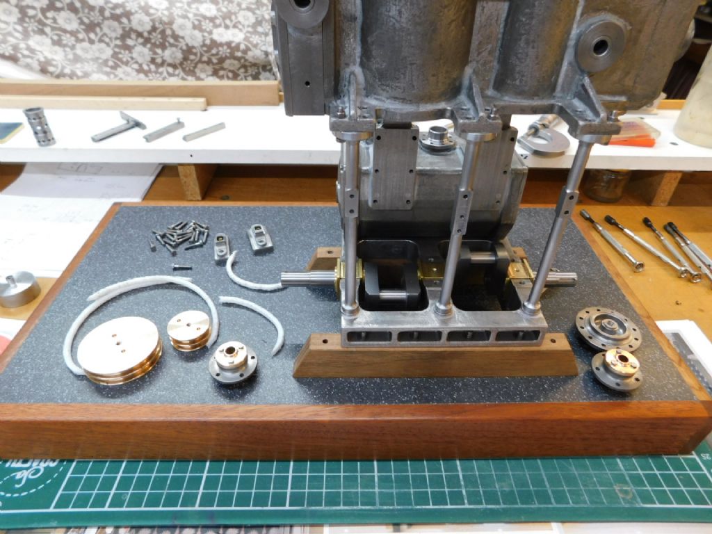
Here are a couple of pics of work so far this week – intention is to stick with this until the end of Feb at least, next up is the crank and main bearings
I found that piece of 12mm dia. precision ground mild steel for the shaft – just too short to make the three main pieces – looks like the centre portion will have to be turned from 1/2"
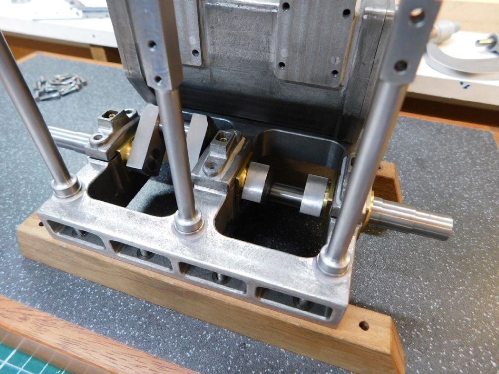
A bit more progress has moved things on a bit with the crank and bearings now made. The crank was fabricated from mild steel components and set together with a combination of press fits and very slightly looser Loctite fits to allow assembly without distortion.
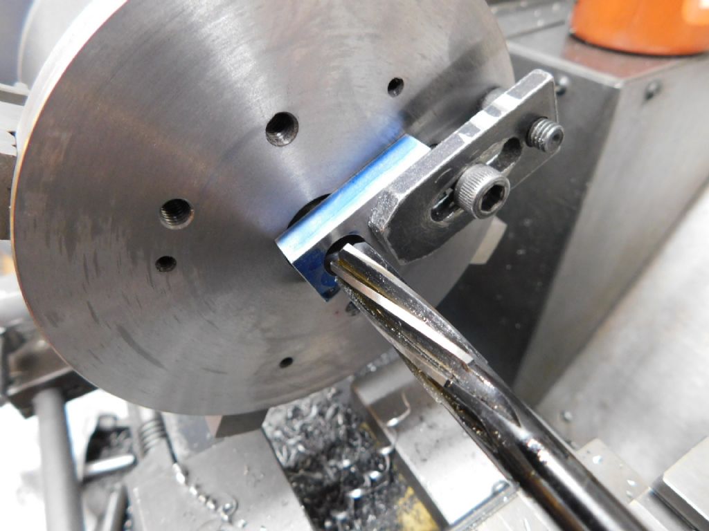
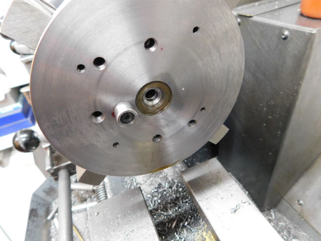
The webs were centred on the mill but bored and reamed on a temporary faceplate to ensure uniformity and squareness of bore
Then a locating button was bolted at the correct throw to ensure uniformity for the throw.
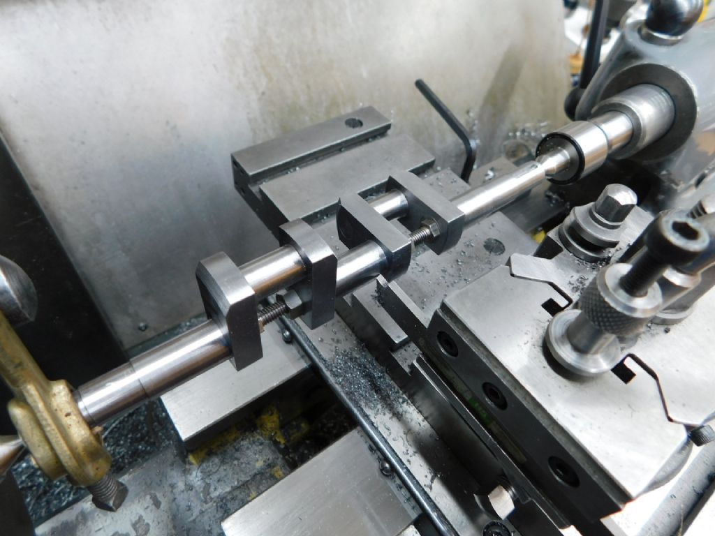
Finally after assembly the mains were finish turned between centres using a parting tool ground square and relieved in the centre of its width. (Pic shows tool after regrinding!)
Bearings are made from bronze – soldered together, machined all over, bored and held on a mandrel to machine the outer surfaces to dimension relative to the bore. I find this a much easier method to ensure positioning than boring to the outer dimensions
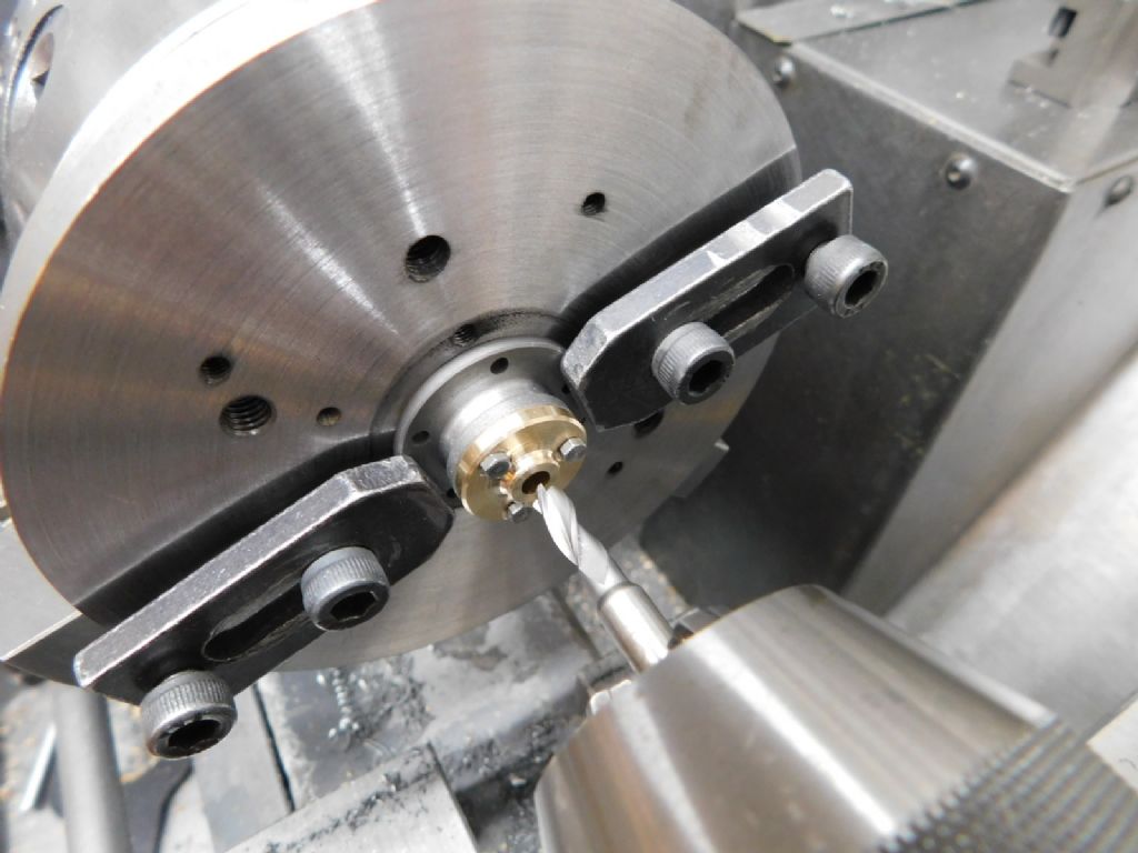
Another temporary faceplate set up to ensure the piston rod gland and bush are as concentric as possible. The previously drilled holes in gland and bush are being trued using an FC3 cutter before opening up to ream them together. The faceplate is bored to a close fit to take the gland register This should convey the benefit of using a 6mm bolt clamping system over the commercially available clamp sets as recently discussed elsewhere.
Pistons were turned from bronze as well and 0.1mm smaller on bore sizes. The grooves take the PTFE packing which gives an exceptional seal with little friction – ideal for running on air at low pressures
That's it as of today – eccentrics next
Do ask if not sure about anything – I just read a post on another forum where the poster got quite upset because people made comments on 'his thread' (???) – not the case here so please do if you want too
After a fair distraction this year I have finally managed to get some work done on this and am at the stage where 'build up' has begun.
The shaft is in 'proper' now with a good running fit in the bearings, the bedplate painted and bolted securely down to the base board so that if any discrepancies in the make up are found they can be dealt with as they occur rather than find out later.
I have uploaded a fair number of images to the album up to the latest stage which should be self explanatory so will not go into detail on them though if anyone does have a question then I'm happy to respond.
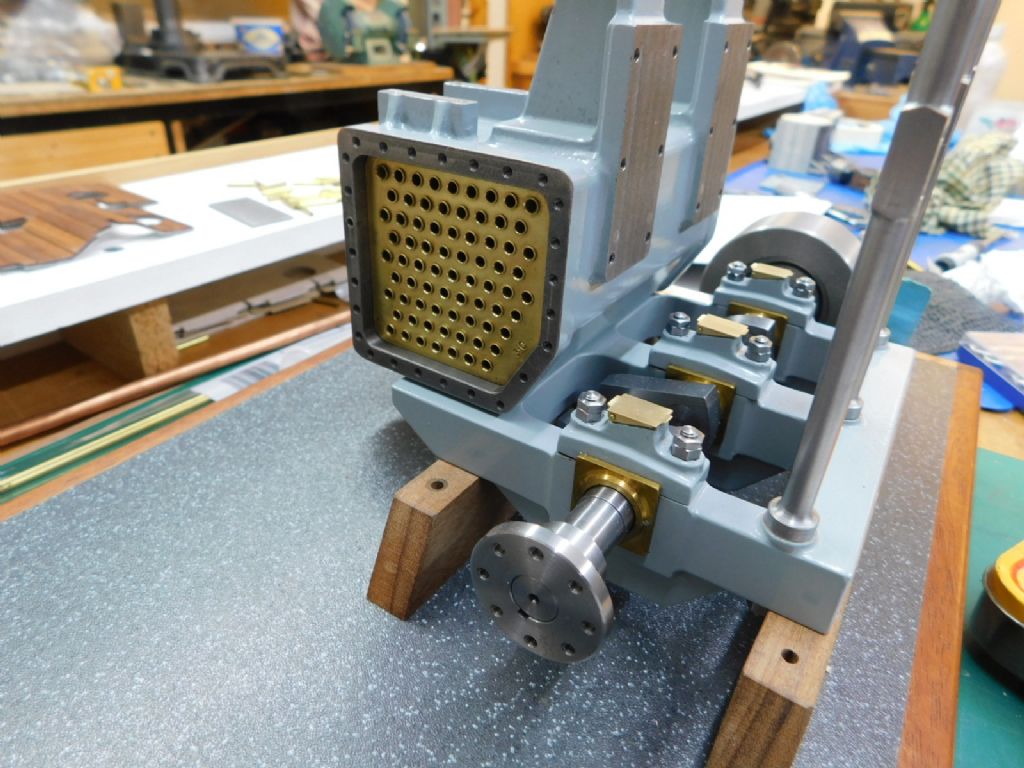
Here's the last pic taken tonight which shows the condenser now tubed out and ready to begin the final work on the cylinder head before it can be set in place.
Hopefully I'll get at least a good couple of months on this now so that should see some definite progress in coming weeks.
Hello Jason, yes it's good to see it come together at last.
Had to spend some time on dealing with the lagging first as I didn't want to strip it down again to do so – tested the patience a bit did that!
The tubing was swaged in at both ends. It's 3mm tube from Albion Alloys so drilled one end 3.05 and the other 2.8. Each tube had one end turned to 2.75 and inserted using a wire as a guide. I made a small anvil and a tapered mandrel to set them. Once all were in I painted all round with Loctite bearing fit (runnier than 638) then each tube was swaged using the drill press to drive a silver steel mandrel.
I was only going to do a few then leave the rest for as you say this will see no steam but once started it soon became a matter of doing them all!
Next stage is to get the pistons in and the head on the standards in order to get the crossheads aligned before bolting the head in place
Work continues and there are several more images in the album.
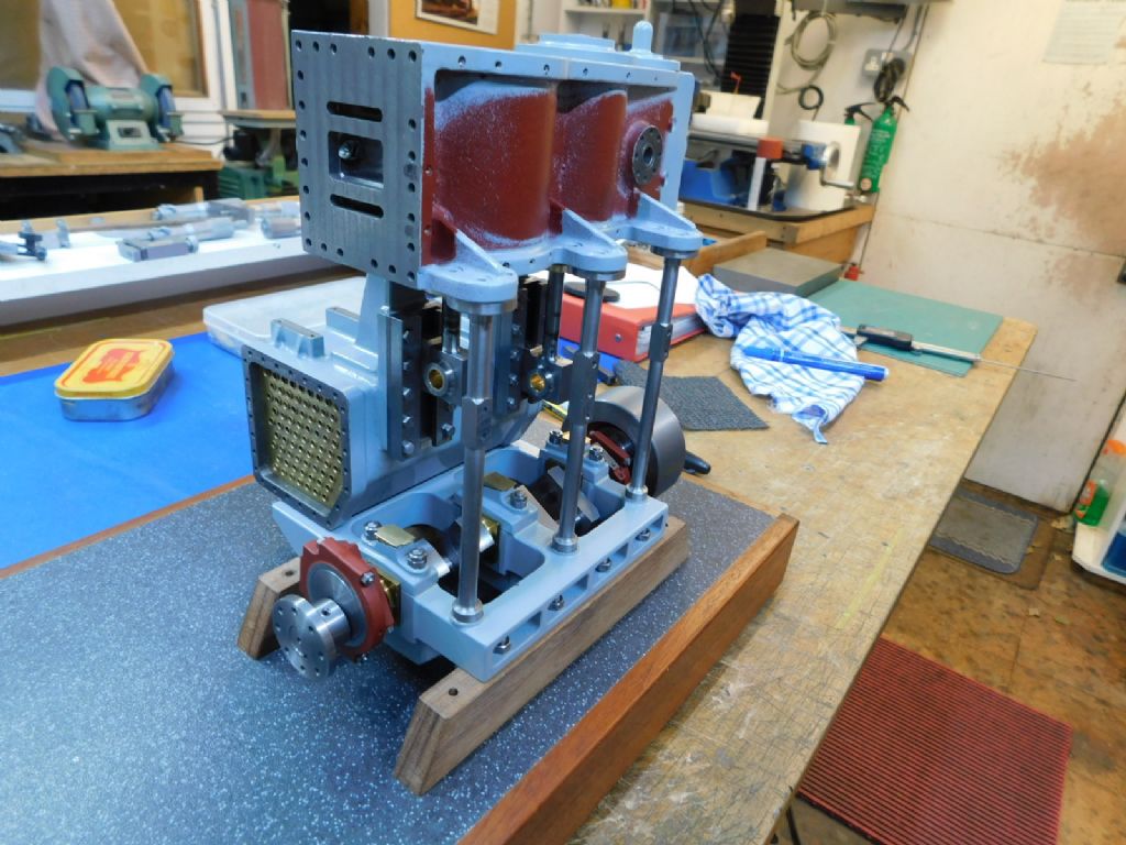
Pistons and rods are now in and the head bolted to the condenser standards. Pleased to say that it all aligns which says something for the drawing dimensioning and all working smoothly with no tight spots.
The original drawing calls for one piece piston rod and crosshead but I split this so that the crosshead slipper bolts on. I wasn't too sure this was correct but it took account of not having to make the entire rods again if it didn't line up. I was pleased to find later that this was how it was actually done full size
Next up to be made are the con-rods so a fair bit of swarf to be made there but all small items from then on.
Anyway, that's the state of play at the moment – here's how it looks as last night.
The whole head and condenser are only placed on at the moment – the base needs to come off for some more clearance work on the bearers.
Jason, for your interest it's actually pale grey not blue – I baulked at red
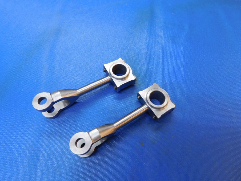
I've just placed several images in the album of the making of the conrods. All machined from solid, the steel used was UHB11, a bolster steel similar to En9.
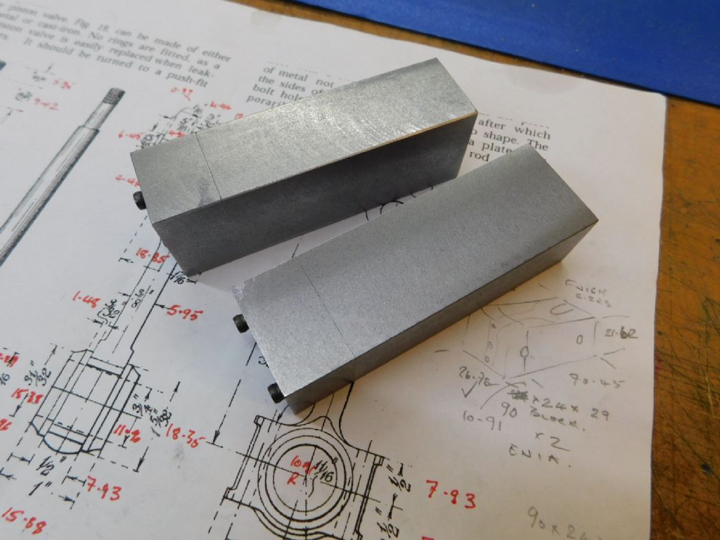
So for most of what time I had in the workshop over the last week or so they began from these blocks milled to overall size plus 0.5mm each face and square on all faces. The blocks were centred and drilled for the two 6BA capheads before cutting the ends and machining the mating faces to form the split line for the big ends.
A fair bit of swarf later they finished as such awaiting the bearings
With no feed back I have no idea if anyone looks at the album but the images in between show the stages – each, as suggested to Doc G on his thread, giving a surface to control the next machining op. The independent 4 jaw was not used, all turning between centres and the rotary milling done on a simple fixture made from a scrap of ally plate as can be seen.
Last op was to drill out and open the 6BA holes to 5BA.
Once those bearings are made I can at last have something turning over
If you do get something out of these images or have any questions about something it would be good to hear from you
Thanks guys, its always good to hear that someone enjoys it.
A full build log is just too time consuming these days hence the occasional updates. I have just added some information to those last series of images however that may help explain the process a little better.
If all goes well with the bearings I should have a 'first turn' over later today/tomorrow.
Will you mount the engine on representative bed plates, frames and double bottoms of the ship it was supposed to be installed in?
Too many fabulous looking models are just stuck on a bit of polished wood – while that is ok, I think for a marine engine, it would look far better mounted on a cut away part of the frames of a ship for example…
Looking forward to the next part of the progress of your engine !
Hi Noel, Derek, thanks for looking in – I'll continue as is then
Derek – It was my intention to do similar, in fact I did make a couple of metal bed-plates initially but decide not to use them. That said I've never really been happy with the two plain wood bearers it currently stands on so your remark has had a positive effect.
Not quite sure what I'll do in detail but I think it will be representative rather than true to anything full size. The base it stands on was previously destined for another engine and I had intended to fill that open space with perhaps a thrust block and a short prop shaft but have decided against that now
I have one last piece of board to make another base, smaller and much more in keeping with the size of the engine so that's a start. Looks like some channel section is going to be required
It's encouraging to see so many visits – it's nicer still to hear from some
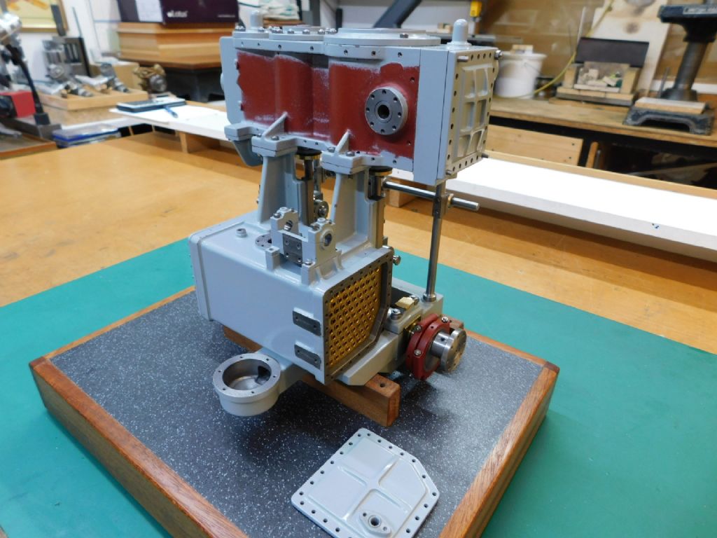
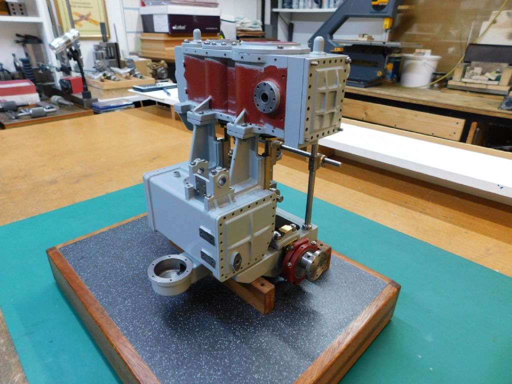
This will be my final post on this project this year and I'm afraid it will be quite a while before the next. Quite a bit of progress has been made this month though not as much as hoped but I now need to set it aside for a while whilst I deal with something else.
I did remove the engine with the intention of doing as you suggested Derek but having cut some wood for cross bearers decided against it due to the potential of not ending up with a flat structure and potential wringing of the bed plate. So the bearers were squared off and I carried on. I have shortened the base and glued a new end piece on which now looks a bit more in keeping.
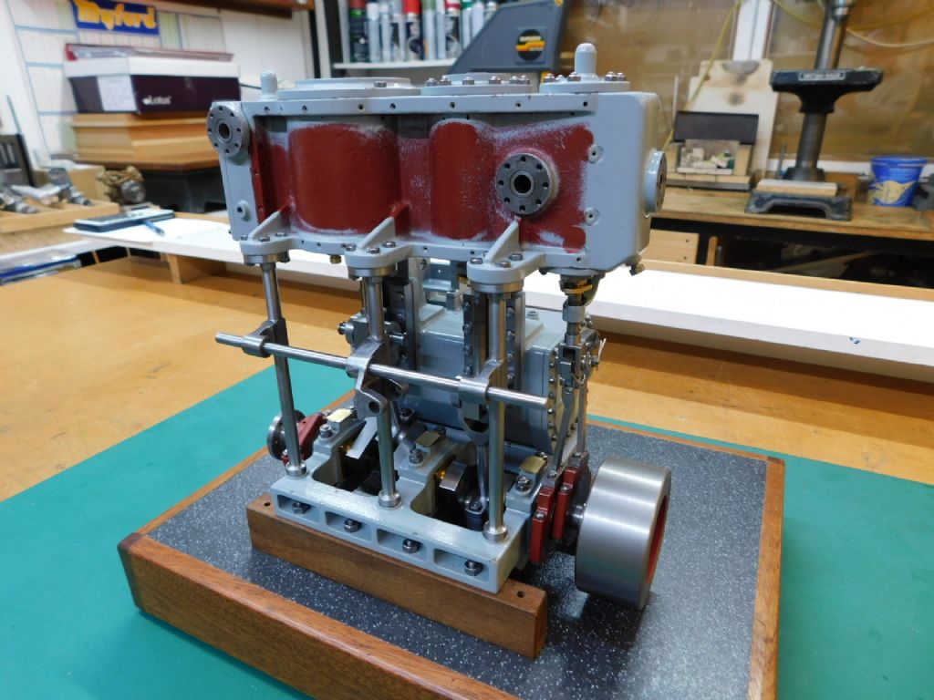
With the conrods made it and the gudgeon pins to suit it could at last be turned over – slight draggy friction but no specific tight spots so well pleased with the overall alignment considering all the potential for error.
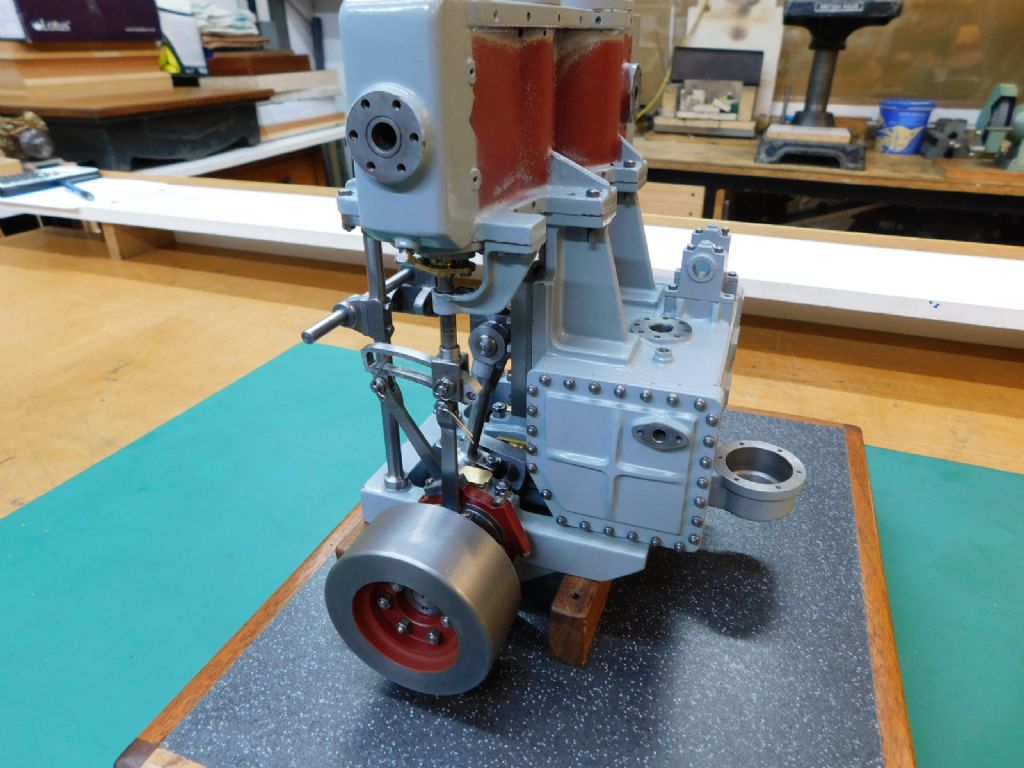
The original drawing calls for two, spaced apart, radial plates to form the expansion link but I decided to change it to the more usual slotted link and the straps milled rather than turned which made things easier when bending the offset.
Pleased to tell that with a jury rigged air line pushed in the inlet it ran quite readily on the HP cylinder only – the only tweak a slightly thicker washer under the piston valve to even things out. Even with the short running time the slight friction soon eased and the engine turns over reasonably smoothly with just a slight resistance
Still a long way to go of course but it bodes well for the LP side.
Here are some pics of the current state of play as of today
Well that's it for a while – I have a plastic project that needs to be worked on for my clubs annual comp in March that will take the weeks before then to finish.
A Happy New Year to all who look in – see you next year – sometime