A Marine Condensing Engine

Advert

A Marine Condensing Engine

Home Forums Work In Progress and completed items A Marine Condensing Engine

Viewing 25 posts - 51 through 75 (of 121 total)
  • Author
    Posts
  • #530207
    John Olsen
    Participant
      @johnolsen79199

      Clockwise or antiCW will depend on which end of the shaft you choose to look at. CW looking from astern seems to be normal for single screw vessels, twin screw ideally should have a handed pair.

      90 degrees is good since it means that your simpling valve will actually work to help start the engine. It doesn't matter which ones leads since they are usually double acting. So either the top or bottom LP inlet will open when either the top or bottom of the HP is about half way through its stroke.

      There is a convention on locomotives for which side leads. If anyone tells them your model is wrong tell them they are looking too close.

      There are at least two different types of simpling valve. The most common is probably the shot of steam type, which just feeds a bit of inlet steam direct to the receiver, putting back pressure on the HP. A more sophisticated type uses more valves and reconnects things so that both cylinders take boiler pressure steam in and exhaust to the LP exhaust side. This gives more starting torque, at the expense of heavy steam consumption, and is more likely to be found on a locomotive than a marine plant. Some old timers called the simpling valve the "God Almighty".

      My own plant will reverse most of the time just by throwing the lever over, but has the shot of steam type of valve for that one time when the wharf is rushing up, you throw over the lever, and nothing happens. Actually it is more likely to fail to reverse in that sort of situation, since you are probably already throttled back to very low inlet pressure to go slow, whereas if you are cruising along at a good speed and throw it into reverse, there is plenty of pressure and the water forces on the prop are likely to move it off dead centre too. So the usual practice is to throw the links over and give it a little shot as well, before you even know if it has decided to reverse. It has an American locomotive style Johnson Bar rather than a more typical marine style screw reverser, since a small boat is more likely to need to reverse frequently than large boats do.

      John

      Advert
      #530221
      Ramon Wilson
      Participant
        @ramonwilson3

        Morning guys, more good stuff, thanks as always yes

        10Ba – I pondered over which way to look at this at first but came to the conclusion this would be looking at it from astern – a RH prop would be turning clockwise which John (Olsen) now confirms. That is how I will do with this model then with the HP leading the LP in that direction.

        Simpling valve – I am aware of what it is for and when it would be used but no other knowlege. I've never fitted one to a model so far. I was under the impression however that this allowed steam (air on this model) at inlet pressure to be diverted direct into either cylinder. John mentions 'the reciever' so now a bit unsure how this is set up.

        That brings me to another question – Nearing the end of the main cylinder parts I realised that the engine as designed has no drain valves. Easy enough to deal with that by fitting the usual side bosses for take off but it lead me to thinking where do marine engine drain points actually drain to. Is it to atmosphere somwhere external to the engine room or into a collector or indeed to the condenser itself. Some full size 'marine' knowlege would be helpful here for sure so if anyone can comment further on the last two points it would be appreciated.

        Began machining the parts for the piston valve block yesterday – all going well and no further mishaps. I'll make sure there are pics of the relevant parts before the JBW goes into action

        Regards – Tug


        Edited By Ramon Wilson on 26/02/2021 08:15:48

        #530223
        JasonB
        Moderator
          @jasonb

          Ramon. it shows two drain tappings on the underside of the cylinder block as well as one on the HP inlet

          #530232
          John Olsen
          Participant
            @johnolsen79199

            Some engines actually have some volume between the HP exhaust and the LP inlet, most don't, so receiver is just a fancy or maybe short way of saying "the piece of pipe between the Hp exhaust and the LP inlet". Of course sometimes this is actually built into the castings so there is no external pipe at all. My simpling valve just takes steam from the main steam pipe to a tapping on the said pipe. It would probably be nicer to take the steam from after the throttle valve.

            My drain cocks just vent to atmosphere. Probably not ideal, it would be nice to save the water. Into the hot well would be my choice, you don't want the vacuum plumbing too complex as leaks in it are hard to trace.

            Unless you are modelling a specific full size prototype, you don't have to worry too much about being strictly correct to full size practice as most possible variations will have been tried somewhere. So as long as it is reasonable and works it is ok

            John

            #530238
            Ramon Wilson
            Participant
              @ramonwilson3

              Thanks Jason and John

              Yes I had noticed the HP inlet drain and having had a fresh look found the two lower drains on the passageways. Doesn't show anything on the GA or for the top of the cylinders though – easily done however.

              John – Understood on the 'receiver' – I'lI look into this further. I can see the logic of not providing areas for potential leaks but on an engine in an engine room the drain must have gone to somewhere specific. Although this is not a scale model per se I would like to make it and it's features as fair to the full size as I can if possible so though this does not have to be 100% it would be nice to follow full size where possible. It's more important (to me) that it's there in more or less the correct manner than it's potential working effectiveness.

              We have close by where I live the 'Lydia Eva' the last remaining steam powered Drifter. It has a triple I believe so may be worth a visit once restrictions lift. That said I do know one of the curators – all I need is to find how to contact him.

              Sun's shining, garden's calling – I'll give the black stuff a rest – well for the morning at least wink

              Regards – Ramon (Tug)

              #530250
              noel shelley
              Participant
                @noelshelley55608

                Hi Tug, Have you got a copy of Ronald H Clarkes "steam engine builders of Norolk " There are many diagrams Etc in it. There were a supprising number of marine engine builder in the county. Noel.

                #530441
                Ramon Wilson
                Participant
                  @ramonwilson3

                  Hi Noel,

                  Thanks for the suggestion but no, I don't have a copy and it's a very long time since I saw one – early model engineering and 'library sourced' days I think. What memory I do have of it was that it was mainly traction engine builders so was surprised by your comment.

                  Late this afternoon I suddenly remembered I had a quite old telephone directory hidden away. Had a look and there was a listing for my old friend Morris who is the curator mentioned previously. Gave it a ring and caught up with him. Obviously the Lydia Eva drifter is affected by lockdown restraints but he assures me the cylinder drain valves simply vent in the 'sump' below the engine and then down into the bilge which is pumped out at regular intervals and removed when the engine is running. As he remarked though, in its former working days that would have been straight over the side! Incidentally Morris was the guy interviewed by Neil Oliver when the vessel featured on the BBC's Coast program.

                  I guess there's no need to be any different then so I'll run the pipes 'below'

                  Tug

                  #530691
                  Ramon Wilson
                  Participant
                    @ramonwilson3

                    Morning guys, I've just had a call from my friend Morris. Apparently after we spoke he and the engineer felt they should take a socially distanced check just to make sure everything was all okay on the boat.

                    Morris took the opportunity wink to have a check where those drains actually end up. So the info, as from the horses mouth and hot off the press, is that the HP and IP top and lower drains come together as four pipes and disappear into the sump as said but the two on the LP cylinder are conected directly to the condenser.

                    As he describes it the exhaust from the LP takes the form of a cast extension of the (horizontal) cylindrical condenser and the two pipes are plumbed directly into that. In the interests of following a full size practice I think I will do the same via a spacer between the exhaust pipe and condenser flanges or similar.

                    Back soon with some pics

                    Tug

                    #530816
                    Ramon Wilson
                    Participant
                      @ramonwilson3

                      Hi Guys – on the home run as far as the cylinder head is concerned – all the major parts done but still seventeen small bits left to do

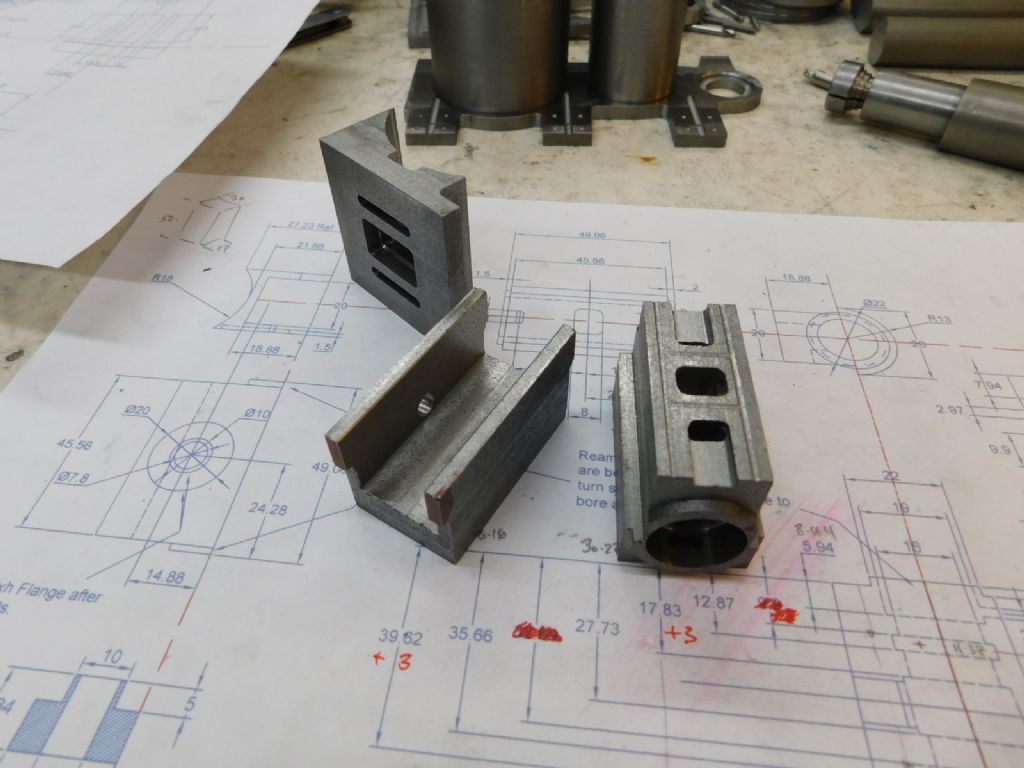
                      Here's the piston valve chamber parts. Slip jointed similar to the condenser the groove is to get a definite JBW seal around the ports. The ports were filled with slices of compressed polystyrene foam packing to prevent the JB from ingressing the ports. Once bonded, that was simply disolved out using a dribble of cellulose thinner in each port.

                      marine compound (45).jpg

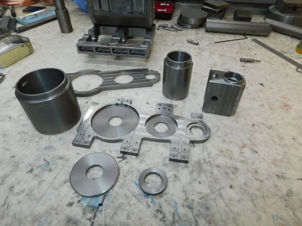
                      The bonded valve chamber along with the other parts. The discs are the infil into the bottom of the cylinders – the original drawing has bores closed at the bottom.

                      marine compound (47).jpg

                      At this moment the piston valve chamber is being bonded to the HP cylinder, just the spacer between the two cylinders to do before it can be put together but I'll wait until all those smaller pieces are done before bonding it all together.

                      It is progressing though, despite that garden distraction – Tug

                      #530938
                      ChrisH
                      Participant
                        @chrish

                        Nice work Tug – just a quickie, what clearance do you give in the slip joints that are then filled with JBW? And are the cylinder bores just fine turned to diameter or did you hone them as well?

                        Chris

                        #530953
                        Ramon Wilson
                        Participant
                          @ramonwilson3

                          Hi Chris

                          It's not measured as such but 2-3 thou I guess. JB has great gap filling properties but ideally it needs to be a loose but not a rattle fit – if too tight then the JB gets forced out. The action of bringing them together seems to self centre the parts, but the idea is to leave a small amount of material on to clean up anyway if required.

                          The cylinder bores as such are off the tool. I did get a hone out in anticipation but the finish in both bores turned out very good if I say so myself – certainly better than anticipated but I may still run the hone through before the assembly for as said the bores are blind and once in place honing will not be possible.

                          Regards – Tug

                          #530972
                          ChrisH
                          Participant
                            @chrish

                            Thanks Tug, what you say about the slip joint clearance & JBW was what I had imagined but it was nice to have the confirmation having not done it yet.

                            Re the bores I was thinking maybe if acute attention was paid to the turning then honing may not be necessary, I hope so!

                            Cheers, Chris

                            #531023
                            Ramon Wilson
                            Participant
                              @ramonwilson3

                              Hi Chris,

                              Both cylinders were done with a boring bar hand ground from a piece of 10mm HSS. Nothing special just a normal cutting edge but with a decent radius. As said the finish was better than anticipated, no doubt down to the meehanite material.

                              I took several spring cuts with the tool cutting on the back stoke – this helps eliminate any tendency to produce a taper. Given the pistons will be fitted with an annular gap and PTFE impregnated yarn seals any slight variation there may be (not detectable using telegauges) will be accomodated by the seal hopefully for a very free and frictionless fit.

                              Regards – Tug

                              #531351
                              Ramon Wilson
                              Participant
                                @ramonwilson3

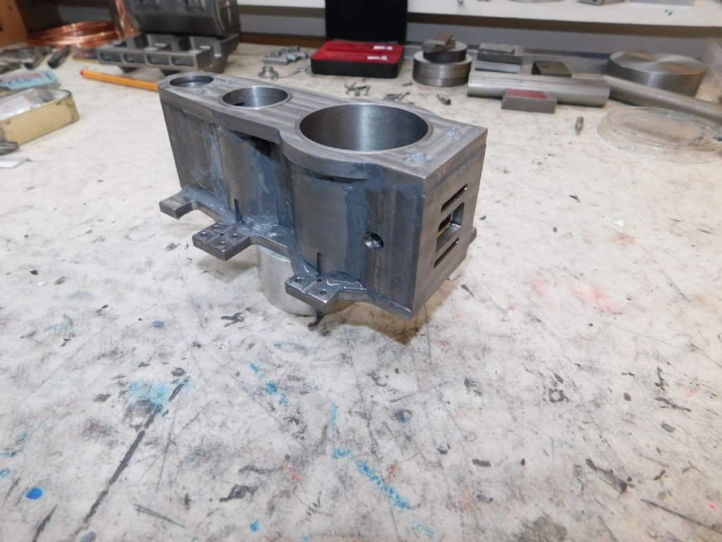
                                Hi guys – just to say it's finally in one piece smiley

                                marine compound (48).jpg

                                It always looks a bit messy at this initial bonding stage but it will soon clean up with a bit of fettling. Further additional parts – gussets, flange bosses etc will get done later as well as improving the fillets. Just four 8BA c'sunk screws on top and four on bottom to keep it all in alignment whist curing. Very 'solid' end result.

                                Hope that result will be of interest

                                Regards – Tug

                                #531358
                                SillyOldDuffer
                                Moderator
                                  @sillyoldduffer
                                  Posted by Ramon Wilson on 03/03/2021 08:35:36:

                                  Hope that result will be of interest

                                  Regards – Tug

                                  Much appreciated by me! Although I'm unlikely to make a model like this, the way you went about it is most valuable: I've been thoroughly cross-fertilized, and it's always good to learn new tricks!

                                  Thanks for sharing.

                                  Dave

                                  #531411
                                  DrDave
                                  Participant
                                    @drdave

                                    It is very impressive, the detail that can be created from bar stock & JB Weld! I must try harder…

                                    #531539
                                    Ramon Wilson
                                    Participant
                                      @ramonwilson3

                                      Well I'm not quite sure my intention has ever been to cross fertilise somone Dave but I think I know what you mean. laugh

                                      Dr Dave – this is one of those processes that you can take as far as your imagination and patience will allow but it is a matter of breaking the item down into component parts and using the JBW as a structural part as well as it's adhesive properties where possible to get the best effects. For instance, where I have a fillet I create a decent chamfer between parts underneath to give more contact area for the JB.

                                      The cylinder head has now been fettled and is ready for the HP inlet cover to be attached before the final machining ops can be made.

                                      Thanks for the comments guys

                                      Tug

                                      Edited By Ramon Wilson on 03/03/2021 23:02:07

                                      #531742
                                      John Olsen
                                      Participant
                                        @johnolsen79199

                                        Just thinking some more about drain cocks, in a lot of full size practice things like this discharge into a copper funnel, which then has a pipe to who knows where. The point seems to be that you can see the discharge so that you know it is working. This is of course especially important with things like gauge glass test cocks, where you want to know if it is discharging steam or water. With the drain cocks, when you are warming the engine it is good to be able to see when it is hot enough inside that it is discharging steam rather than a mixture of steam and water.

                                        regards

                                        John

                                        #531749
                                        Ramon Wilson
                                        Participant
                                          @ramonwilson3

                                          Hello John, Thanks for the further input.

                                          I can see the logic of what you are saying though when I was doing the Corliss engine and studied lots (and lots!) of images I could find no evidence of that on stationary engines. Virtually all that I can recall just disappeared into the foundations and I presume either eventually to atmosphere or into the exhaust system post condenser.

                                          The Lydia Eva engine previously mentioned is a triple expansion engine built originally by Crabtree & Co of Great Yarmouth. I have no way of knowing if the piping as previously described was original or done when the vessel was restored but would hazard a guess that if it were not then all six pipes would have been sent to the 'sump' (as it was referred to).

                                          Though I have more or less decided to follow that set up I will look into it a bit further. I have just received a DVD with literally countless old maritime books to peruse plus a very lucky find of Volume 2 of the Verbal Notes for marine engineers – must surely be something in there.

                                          Hope to have some pics of latest progress at the weekend

                                          Regards – Tug

                                          #533507
                                          Ramon Wilson
                                          Participant
                                            @ramonwilson3

                                            Hi Guys, a little later than hoped for but the major 'casting' parts of this project have now been accomplished. It's taken two days to rid the workshop of the patina of black dust that had got everywhere and hopefully the hands will begin to freshen up too!

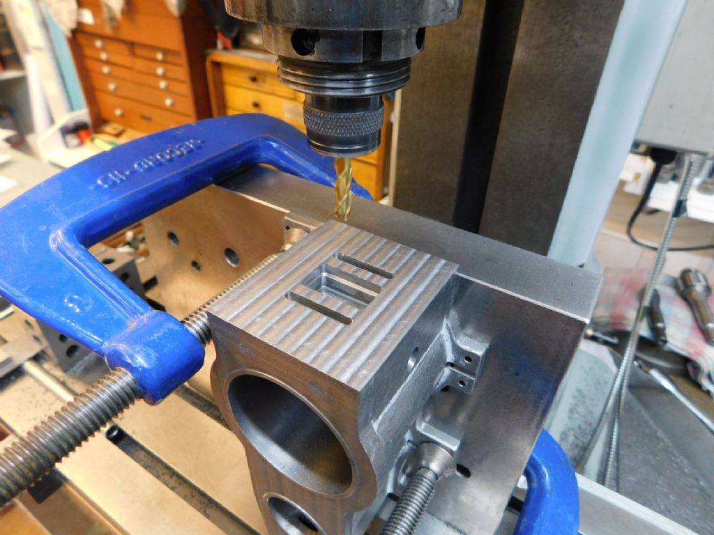
                                            Last op was to mill the valve face flat – 6mm cutter with 5mm overlaps to give a flat if not visually attractive surface.

                                            marine compound (49).jpg


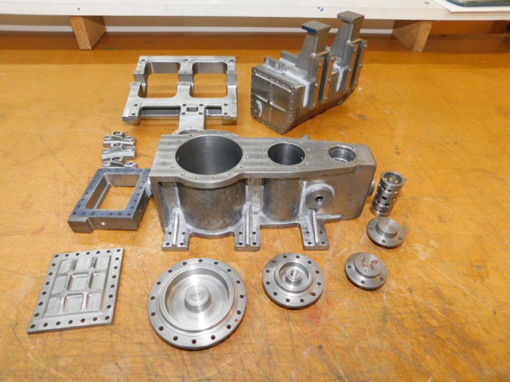
                                            All the parts for the final make up. The two cylinder heads are not quite finished as yet with webs to put in ……

                                            marine compound (50).jpg


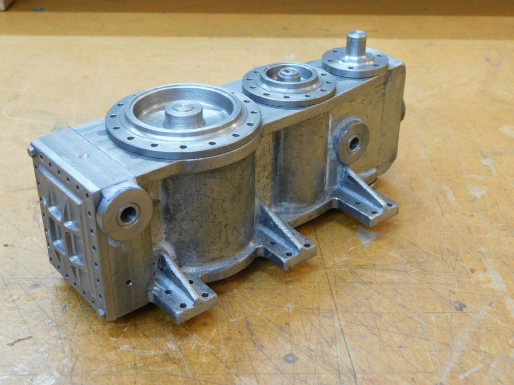
                                            …….. and the cylinder head assembled. Holes in those side flanges will be dealt with later as will the outer diameter of the piston valve chamber.

                                            marine compound (51).jpg


                                            That's it for this stage – I'm going to take a break from it now as the garden will take precedence over coming weeks and there are other matters that require attention too.

                                            Back sometime then but definitely not next week!

                                            Thanks for looking in – hope you've found the method of interest and enjoyed the pics – there are more in the album of course


                                            Regards – Tug

                                            Edited By Ramon Wilson on 12/03/2021 22:56:13

                                            #533528
                                            Dr_GMJN
                                            Participant
                                              @dr_gmjn

                                              That’s looking brilliant. Will you be spot-facing the mount bracket holes?

                                              #533562
                                              Ramon Wilson
                                              Participant
                                                @ramonwilson3

                                                Hi Doc, yes, this is just the initial stage in establishing the casting shape(s). There's quite a few holes that need spotfacing including some reverse ones on the base. First up will be getting a coat of primer on to see if any of the fillets need improving/fettling.

                                                There's a web that needs adding to the base – missed that first time! – and various bosses to be added.

                                                But, as said that will be a while before I get back on it. Very pleased with the outcome so far and looking forwards to dealing with the remaining work

                                                Thanks for looking inyes

                                                Ramon (Tug)

                                                #533913
                                                DrDave
                                                Participant
                                                  @drdave

                                                  That is impressive: thank you for showing us how you assembled the raw parts to make the "castings". I have learned a lot of the Black Art of cast iron & JB Weld!

                                                  Dave

                                                  #533950
                                                  Ramon Wilson
                                                  Participant
                                                    @ramonwilson3

                                                    Ha from the residue left 'Black Art' is indeed an apt description Dave wink

                                                    Glad you have got something from it, I'm sure it won't be everyone's cup of tea but it is, to my mind, a viable way of ending up with a 'casting' that not only looks a reasonable rendition but is functional as well.

                                                    I'm surprised no one has questioned its potential to withstand the forces involved. For myself I'm more than content that it will but like most posting on building anything many look in but so few comment.

                                                    Anyway thanks for your comments – it will be a while before 'phase two' begins but I will continue to post once back on it again

                                                    Regards – Tug

                                                    #533961
                                                    JasonB
                                                    Moderator
                                                      @jasonb
                                                      Posted by Ramon Wilson on 15/03/2021 08:21:46:

                                                      I'm surprised no one has questioned its potential to withstand the forces involved. For myself I'm more than content that it will but like most posting on building anything many look in but so few comment.

                                                      Maybe like me they have seen your previous proof of JBWelds holding power and enjoying just quietly following along. Maybe if you showed your soft jaws that may draw a few commentssmile p

                                                    Viewing 25 posts - 51 through 75 (of 121 total)
                                                    • Please log in to reply to this topic. Registering is free and easy using the links on the menu at the top of this page.

                                                    Advert

                                                    Latest Replies

                                                    Viewing 25 topics - 1 through 25 (of 25 total)
                                                    Viewing 25 topics - 1 through 25 (of 25 total)

                                                    View full reply list.

                                                    Advert

                                                    Newsletter Sign-up