Having downloaded and printed off the pdf on this engine and then gone through and studied all the drawings, although not read all the construction notes at this stage, has given me a far greater appreciation of what has gone into your condenser to replicate by fabrication what is called for quite a fair casting in the original article. I do like that mindset than can think in that direction.
If I be a pain, could I ask:
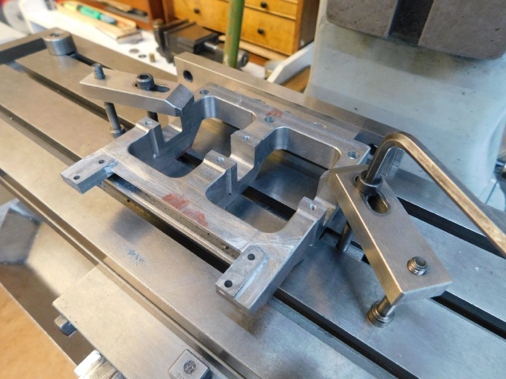
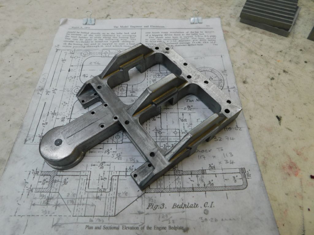
I see the front of the bedplate has been hollowed out between top and bottom plates, is that replicated at the back and underneath at all?
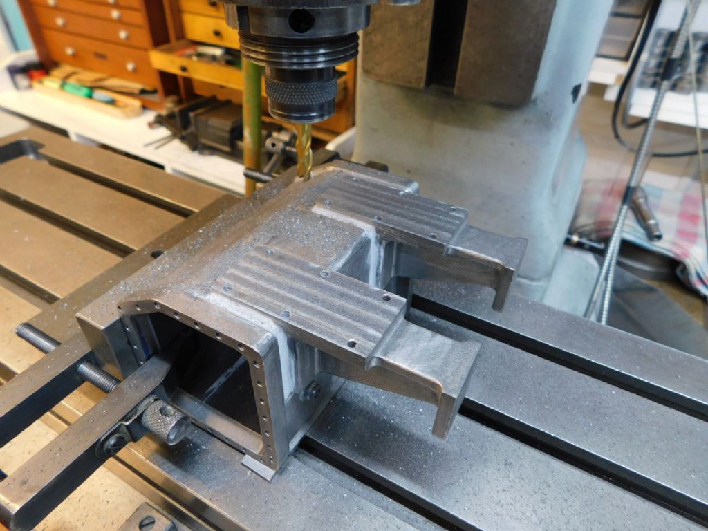
Are the supports on the condenser – for the rear of the cylinders etc etc – fixed by c/s screws into the parts through the condenser walls as well as by the now famed JB Weld? (where would you be without JBW?!)
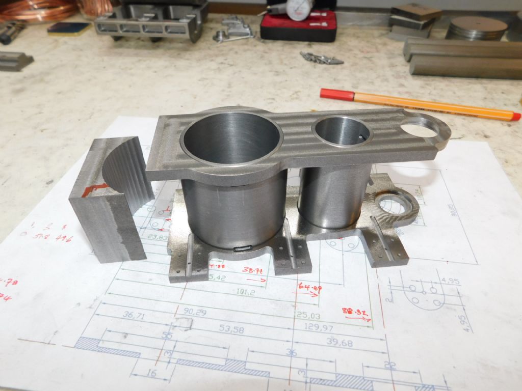
Why did you make the main bearing caps from two pieces – I assume it is a top and a bottom pieces – was it to save weight?
I think I might well work this up for a future project, noting the drawings in dimensions in red for the scale to be worked in, but might do the drawings at half scale instead of 5/8th scale; however I will see how this pans out all the way through the fittings and fixtures as well as part sizes before deciding what scale. I will do them in imperial not metric as I work in imperial for preference, a thou means more to me, I can visualise them better, than bits of a mm although I will/can work in metric.
Finally, can I ask that you continue to post as many pictures – you are generally very generous in this respect – as you can as you progress the build, close-ups as well as general views, as pictures are worth a thousand words as they say.
Looking forward to the next installment,
Chris
PS: For the record I am also a manual twiddler, no CNC, the mill has a very nice DRO but only a dial gauge on the lathe longitudinal feed. I too am too old to do this CNC stuff, can't get my head around drawing in 3D never mind whats required for CNC, 2D stuff is still fine for me!
Edited By ChrisH on 19/02/2021 19:31:08
 Ramon Wilson.


