A Lightweight Husky

Advert

A Lightweight Husky

Home Forums Stationary engines A Lightweight Husky

Viewing 16 posts - 26 through 41 (of 41 total)
  • Author
    Posts
  • #576266
    Clive Brown 1
    Participant
      @clivebrown1

      A Question primarily for JasonB.

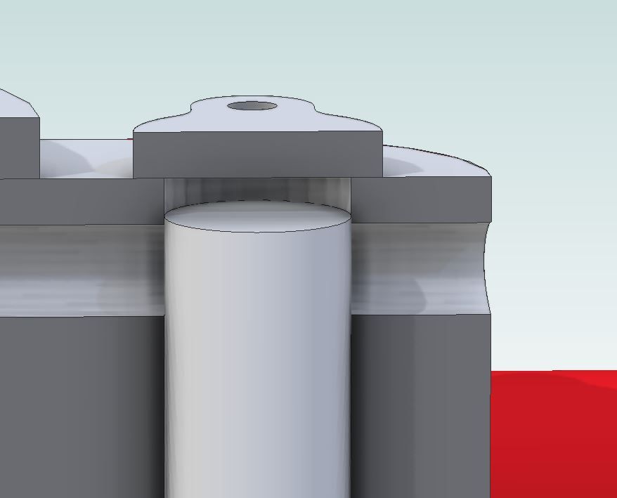
      I've been looking at the Husky cam design. The valve movement of 1/8" is the same as the port diameter. If the valve is set to fully uncover the port it seems likely to allow air/steam leakage into cylnder when closed. Is there any benefit in slightly increasing the valve travel to provide a better margin for port closure?

      Another doubt that occurs is that the cam boss is 5/16" id x 7/16" od. Not much meat for the grub-screw to thread into.

      I'd be very interested in any comments.

      TIA

      Advert
      #576273
      JasonB
      Moderator
        @jasonb

        I felt the same so left the valve long then on final assembly put the end of the digi callipers down the valve hole and trimmed the valve so that it came 0.25mm above the top of the inlet hole when in the fully up position

        husky valve.jpg

        As part of the slimming down of the engine I reduced the crankshaft to 6mm dia and the boss is 10.5mm so I gain a little bit more depth of thread but a 12mm boss would be better though the cam would need enlarging to suit.

        #576289
        Clive Brown 1
        Participant
          @clivebrown1

          Thanks Jason. I fancy making a Husky as an interesting exercise.Your reply will encourage me to experiment a little bit with the valve arrangement.

          #576649
          Neil Wyatt
          Moderator
            @neilwyatt

            Wonderful engine, (or is it a very elaborate device for blowing raspberries… )

            Neil

            #576799
            Ron Laden
            Participant
              @ronladen17547

              Happy Christmas Jason

              Your re – design certainly improved the look of the engine not so bulky and more open. It runs nicely, certainly can get a lick on, sounds good to.

              Very nice.

              Ron

              #581859
              Clive Brown 1
              Participant
                @clivebrown1

                I've not built a uniflow engine up until now so here's my take on Husky, inspired by this thread. Not as elegant as JasonB's but it runs.

                Basic dimensions are pretty much to the magazine plans. I've slightly increased the cylinder clearance volume at TDC to reduce compression. The valve travel is slightly longer in an attempt to lessen leakage into the cylinder when the inlet port is closed, also the flywheel is heavier.

                (This post is also a first try at embedding video)

                Edit:- was hoping the video would open automatically, however, the link seems selectable and clickable but not ideal.


                Edited By Clive Brown 1 on 23/01/2022 10:07:22

                Edited By JasonB on 23/01/2022 10:22:23

                #581870
                JasonB
                Moderator
                  @jasonb

                  Looks to be a good runner and a lot less jumpy than mine unless you have a secret fixing holding it to the bench top

                  #581874
                  Clive Brown 1
                  Participant
                    @clivebrown1

                    Thanks for moving the video Jason. It's not fixed but it does start to wander around the bench if I tun the pressure up.

                    #585981
                    duncan webster 1
                    Participant
                      @duncanwebster1

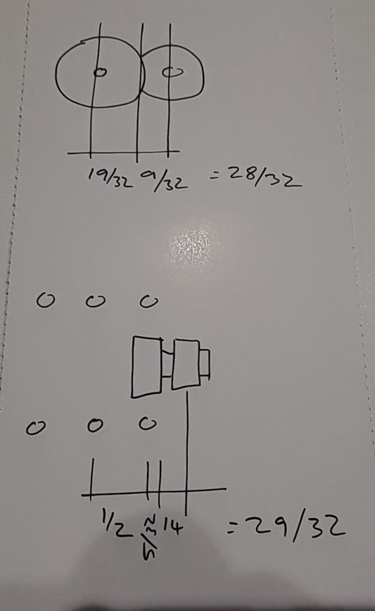
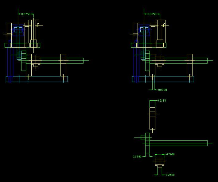
                      Before jumping in I thought I'd redraw the Popular Science drawings in CAD. Either I'm missing something or the inboard bearing should be moved 3/32 to the left, not as shown in line with the right hand pillars. Anyone else found this? Jason's models/photos seem to be as PopSci, but the cam looks different, lobe not central

                      If this is going to appear as a series in ME I'll has hold off

                      #586007
                      JasonB
                      Moderator
                        @jasonb

                        Just had a quick look at the PS drawings and I make it 1/32" difference , did you allow for the flats on the cyl and valve?

                        husky cts.jpg

                        After resizing mine came out to 21mm for both, I also increased the boss on one side of the cam as 3mm would have been a bit small to get a half decent sizes grub screw into.

                        I don't think I will be writing this one up for ME.

                        husky section.jpg

                        #586017
                        Clive Brown 1
                        Participant
                          @clivebrown1

                          Duncan,

                          I made mine to the imperial dimensions in the magazine and it fitted together OK. Can't think where the 3/32" could come from. I did at first wonder if you had turned the con-rod so that the big-end boss took up that dimension, but it's 1/8". The cam and valve rod centre lines would be displaced if you moved the inboard bearing.

                          Other changes I made wouldn't affect the bearing position.

                          #586120
                          duncan webster 1
                          Participant
                            @duncanwebster1

                            Hmmm. If I put the conrod boss in as per left hand view the cam is offset from the valve, if I put the boss out as per Jason model I have to move the bearing, still can't see where I've gone awry. Yes I've allowed for the 1/32 flats

                            setout.jpg

                            #586121
                            duncan webster 1
                            Participant
                              @duncanwebster1

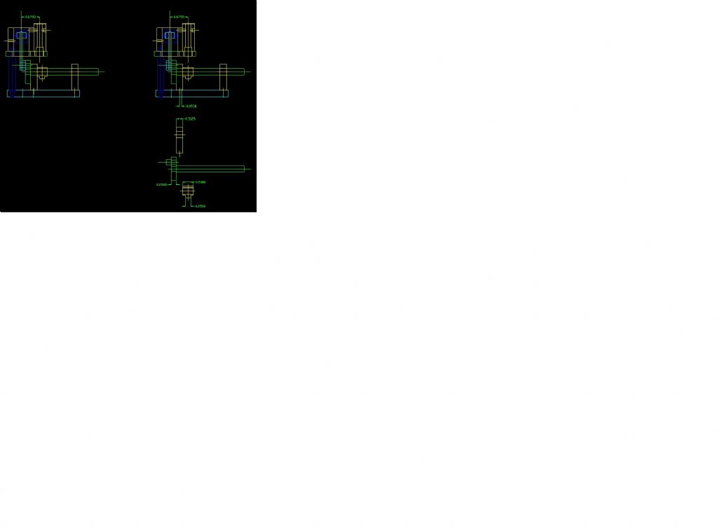
                              Sorry about the picture, it's a png from a screenshot converted to jpg using Paint, anyone know how I can make it bigger?

                              #586127
                              duncan webster 1
                              Participant
                                @duncanwebster1

                                try thisscreenshot 2022-02-18 182525.jpg

                                #586130
                                JasonB
                                Moderator
                                  @jasonb

                                  That's better and I can see the problem now.

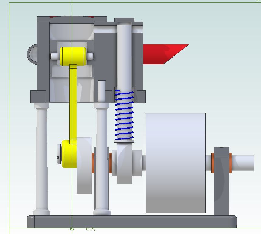
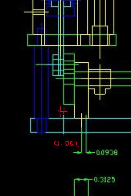
                                  If you look at the light blue line representing the ctr line of the middle column that is not on the same ctr line as the cylinder by what looks like about 1/16" marked in red which is why you are getting 3/32" yet the drawing "error" is only 1/32"

                                  Move the cylinder and columns to the same ctr line and also make the crank pin a bit longer so you have some float and it wil run with bearing lined up with end pair of columns

                                  husky off ctr.jpg

                                  #586139
                                  duncan webster 1
                                  Participant
                                    @duncanwebster1

                                    Gotcha, Thanks

                                  Viewing 16 posts - 26 through 41 (of 41 total)
                                  • Please log in to reply to this topic. Registering is free and easy using the links on the menu at the top of this page.

                                  Advert

                                  Latest Replies

                                  Home Forums Stationary engines Topics

                                  Viewing 25 topics - 1 through 25 (of 25 total)
                                  Viewing 25 topics - 1 through 25 (of 25 total)

                                  View full reply list.

                                  Advert

                                  Newsletter Sign-up