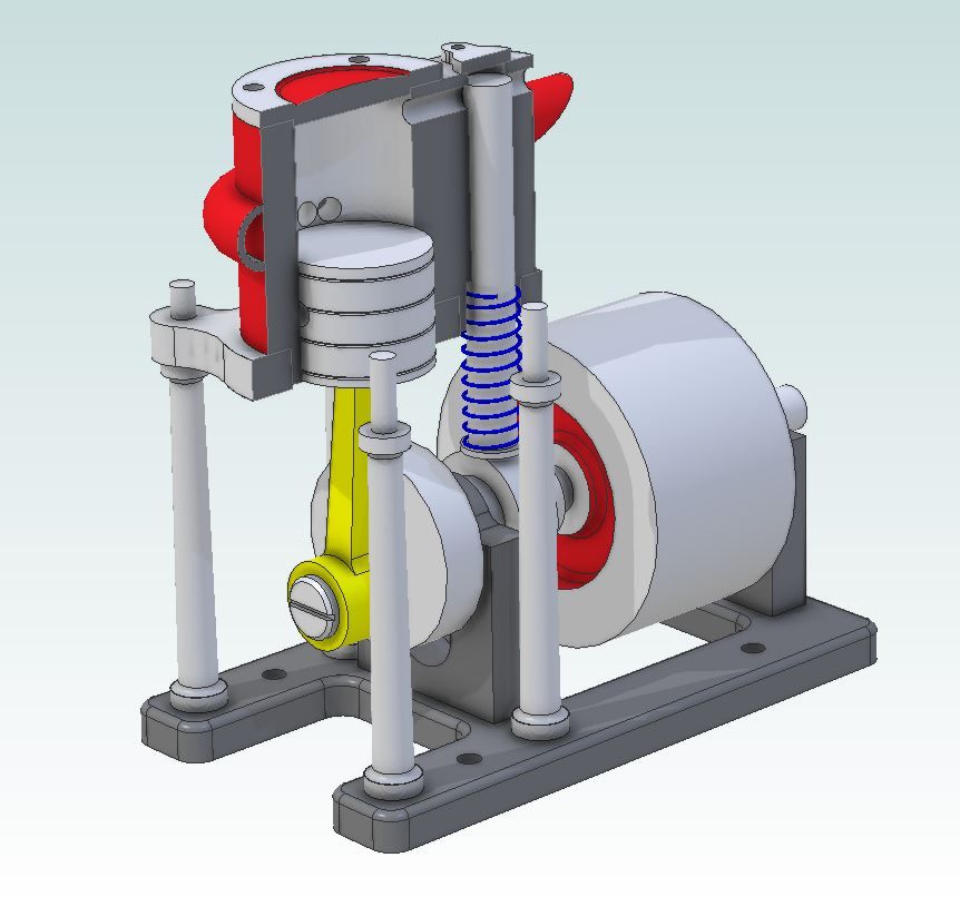
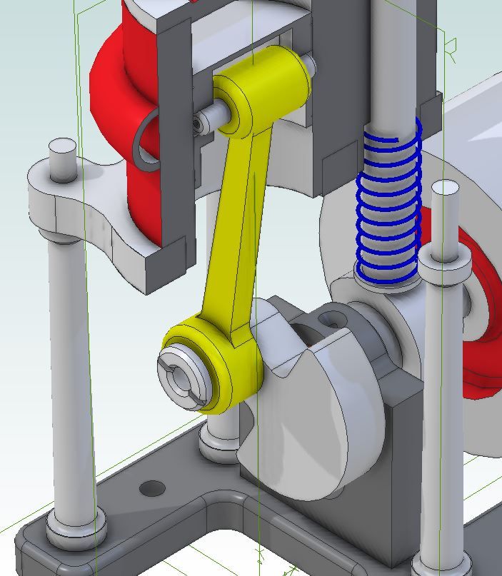
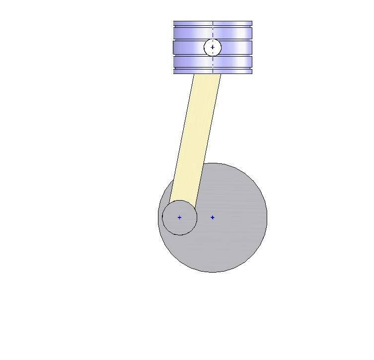
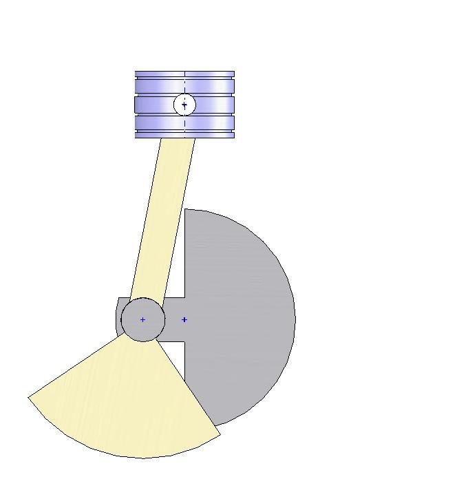
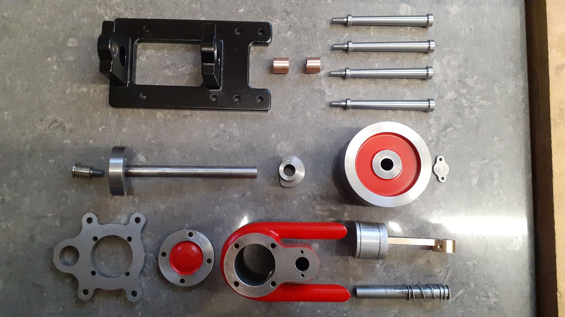
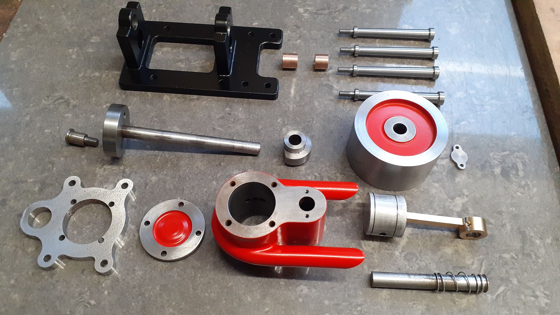
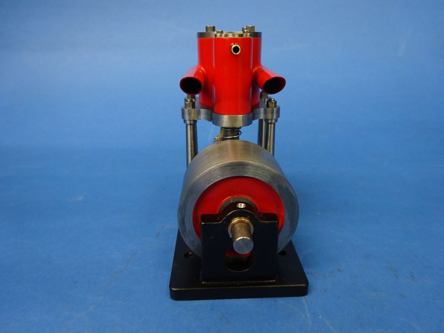
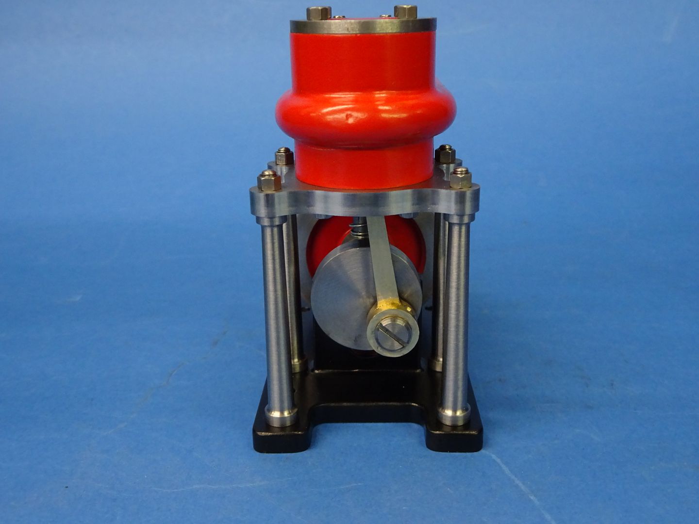
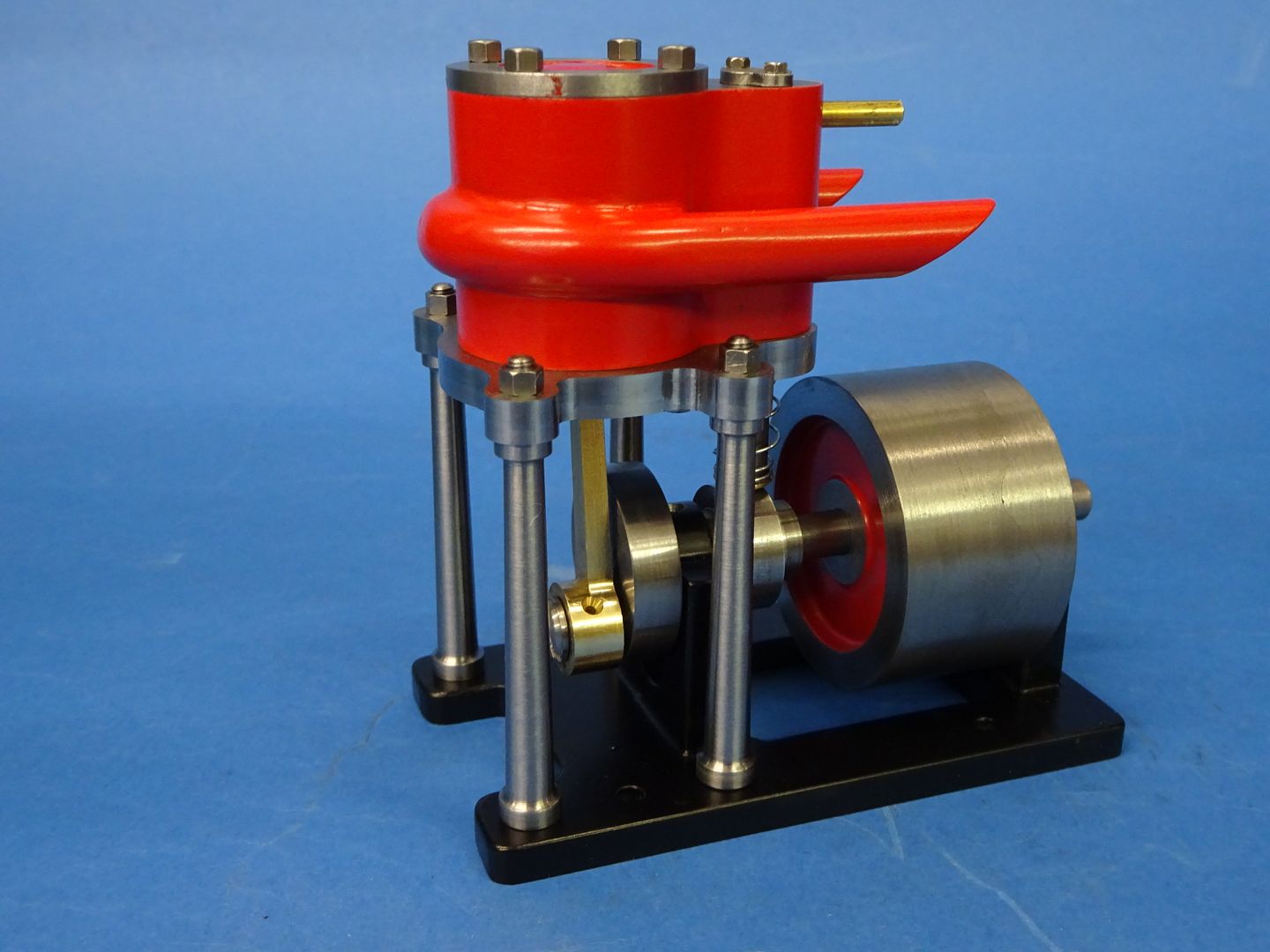
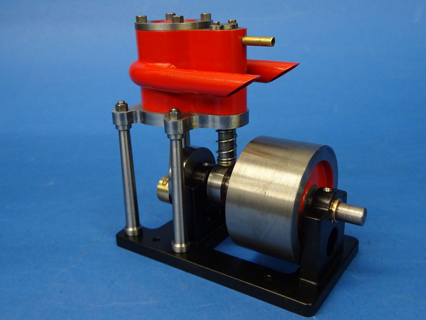
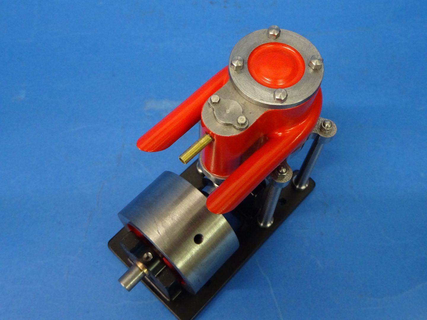
All interesting stuff, I may have a play with the moving bits at some time to see if I can tame it's down a bit but as I have just got some measurements of the next one in the series will probably concentrate on that instead.
I was in two minds as to what to make the cylinder from. Cast iron would have been nice but not so easy to solder the exhaust to it, Bronze and brass would have been easy to solder but it's a bit of a lump and I did not have much suitable in stock (at least that I wanted to cut into) so I ended up going for 230M07 (EN1A) as it's not really any more likely to rust than iron particularly as I'm mostly going to run on air.
So a piece was sliced off a 2" bar with the trusty Femi band saw, faced each end and then mounted on the CNC. The two ctr drilled holes are to make it easier to locate the bores for machining on the manual machines.
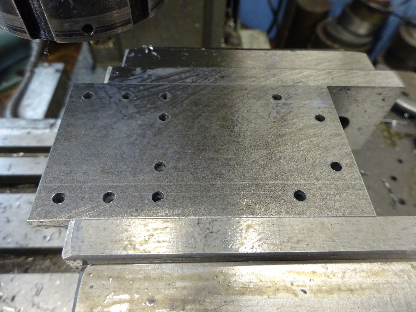
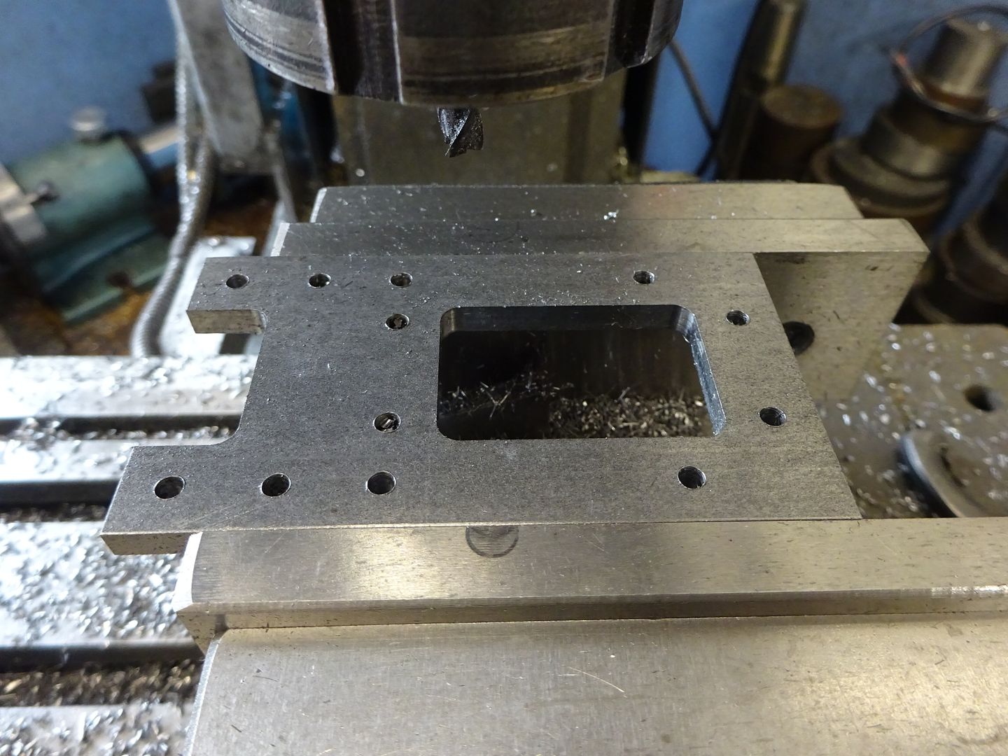
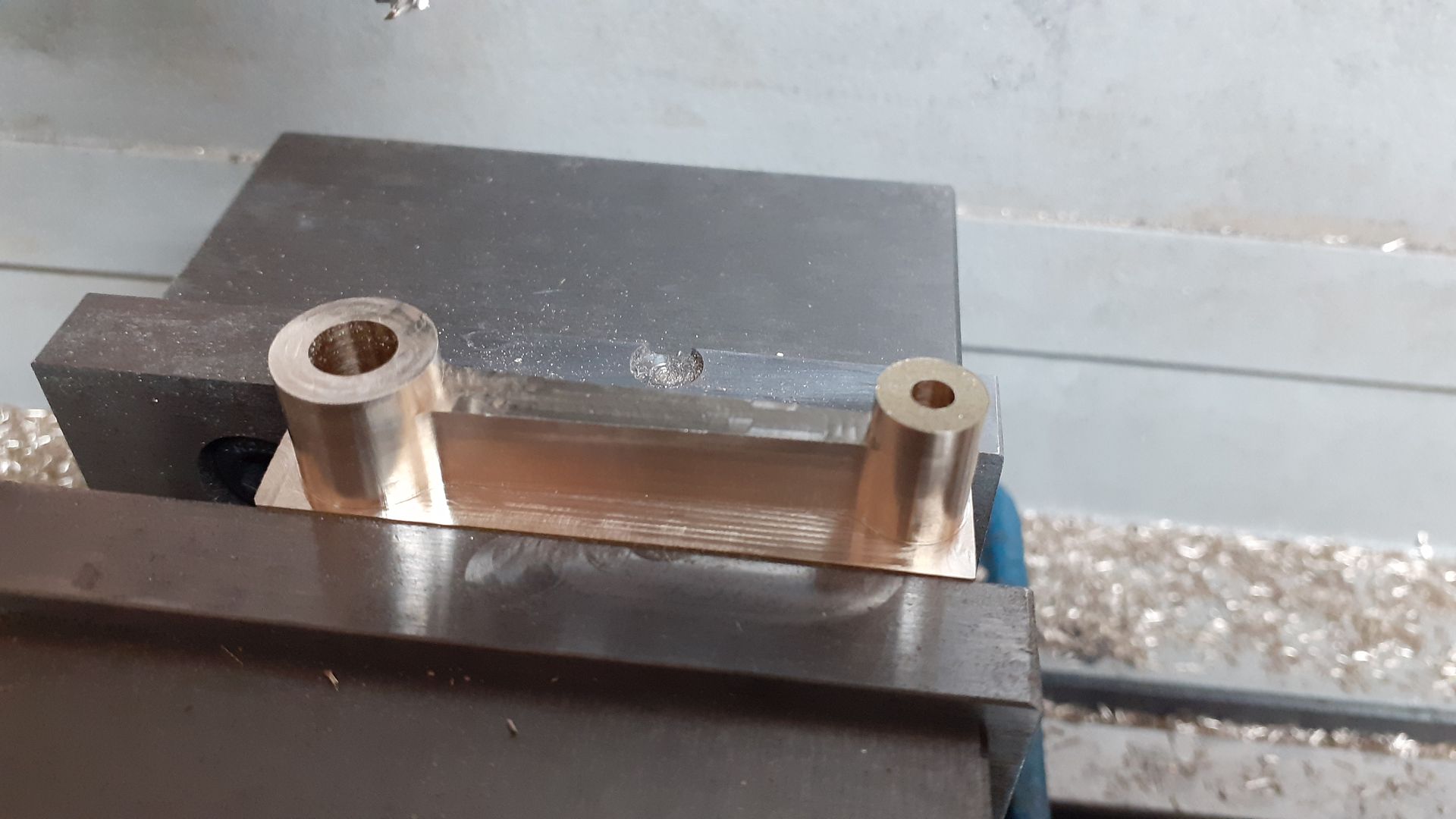
While the mill was switched on I also did the entablature. The fit of the cylinder's spigots was very good into the holes and would have been a good press fit but that was a bit tighter than I wanted so a quick adjustment of the tool diameter in F360 and an extra 0.01mm was taken off the bores which gave a firm push fit.
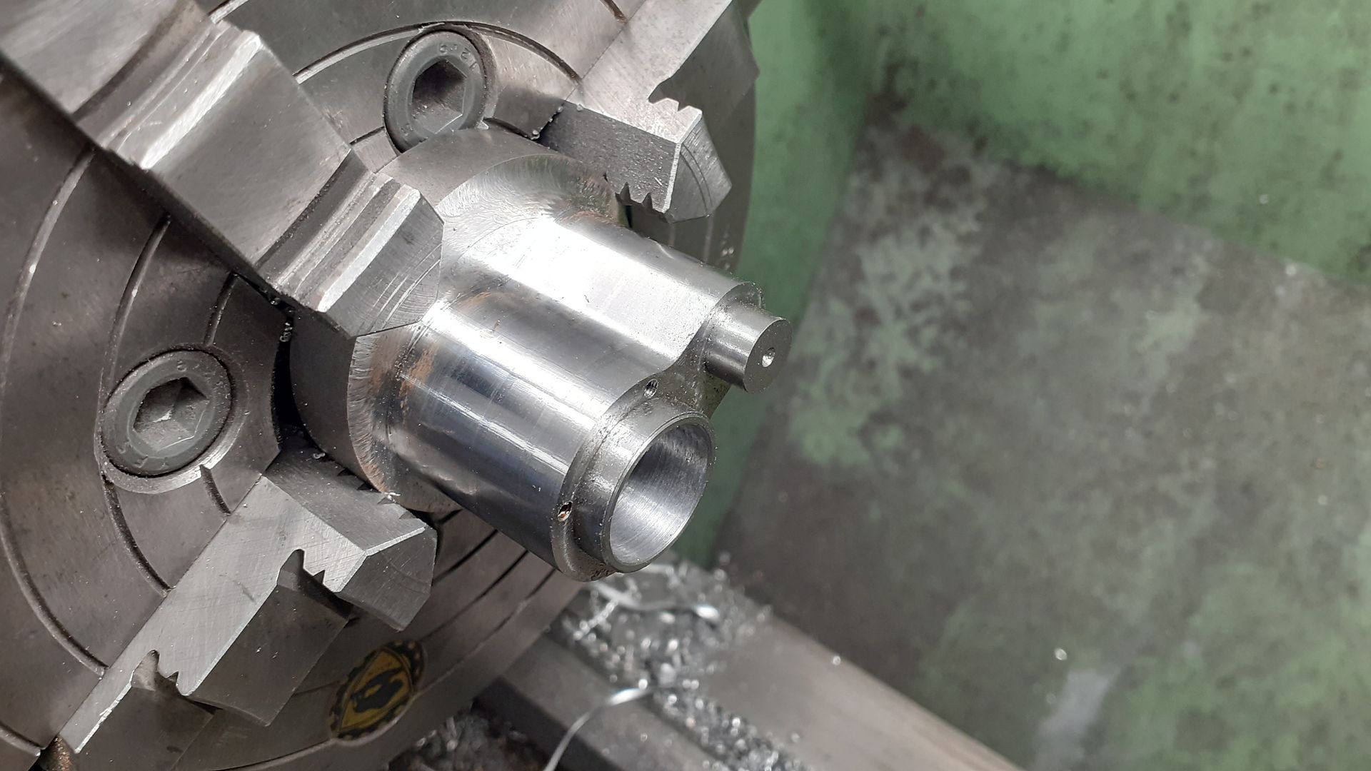
I then held the cylinder in the 4-jaw, clocked the ctr drilled hole true and then drilled and finally bored it out to 18mm

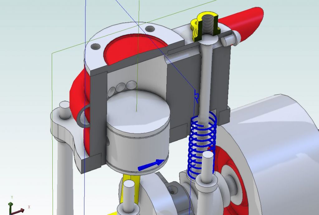
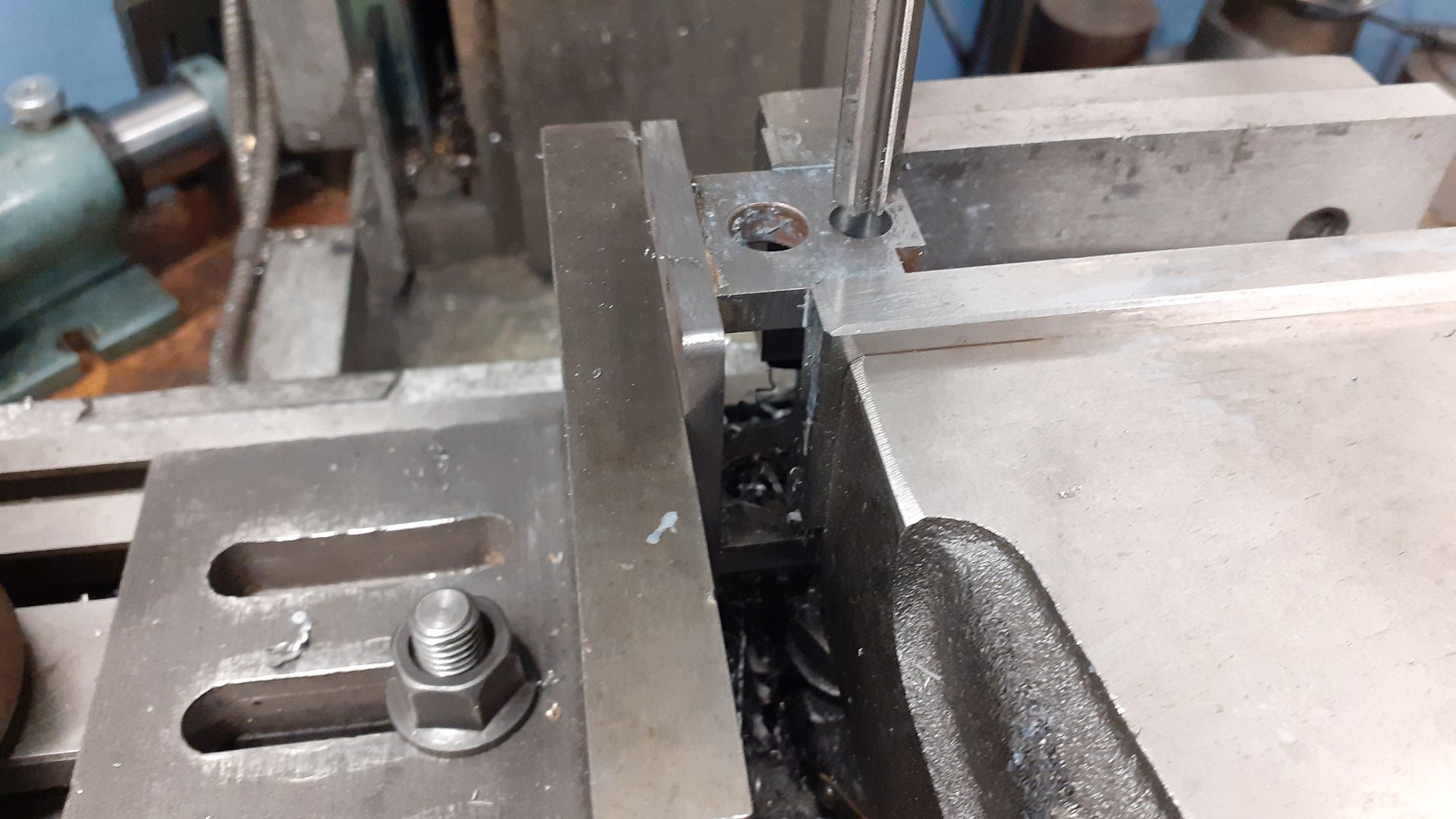
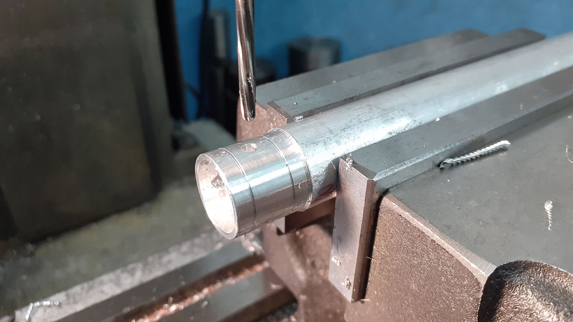
The valve hole was a bit too far off central to make holding in the 4-jaw easy so I used the mill to drill and ream the hole out to 6mm with a machine reamer

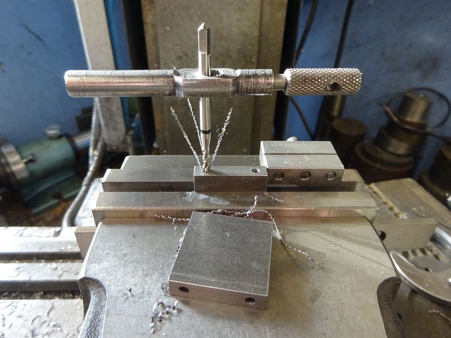
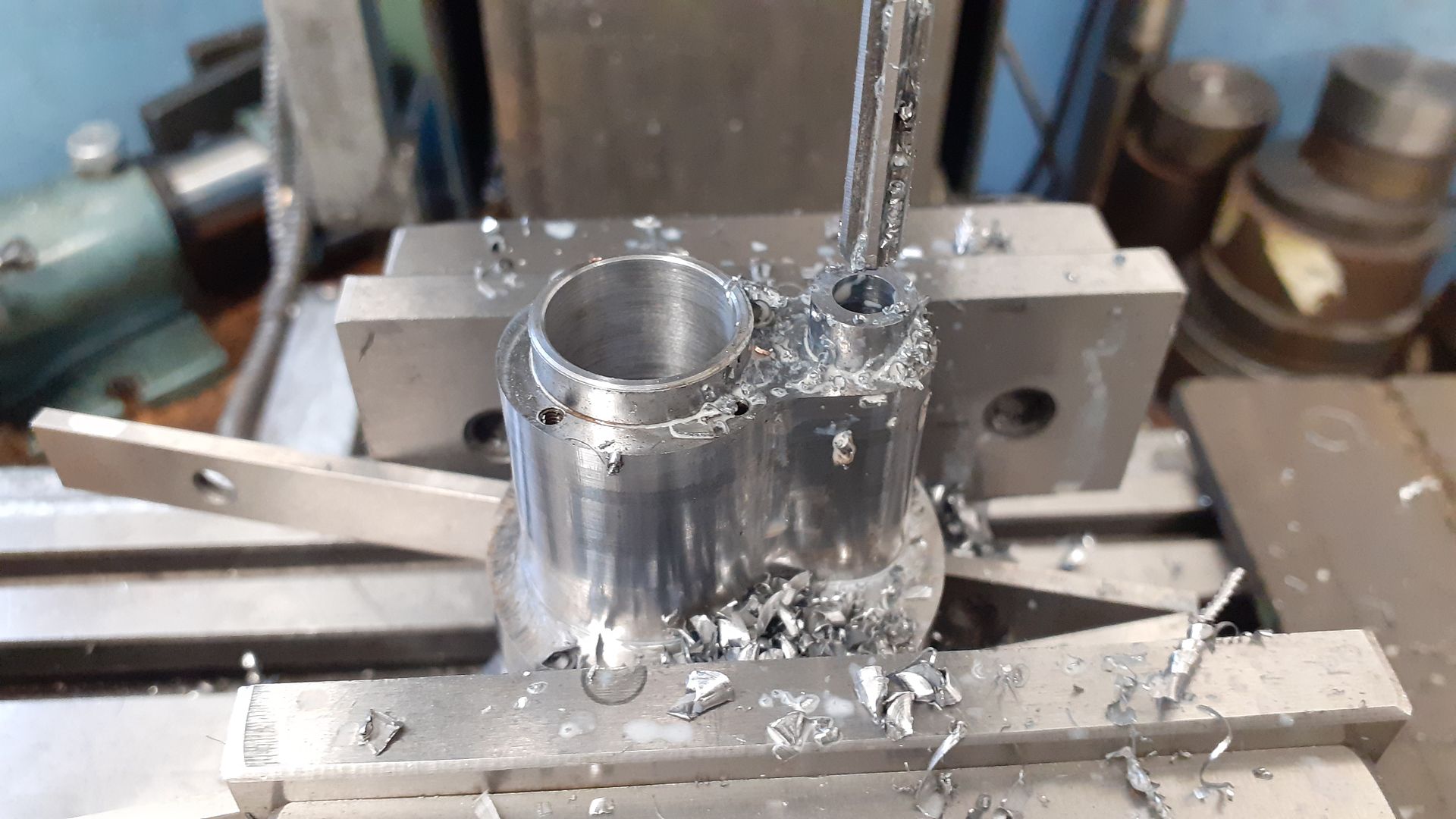
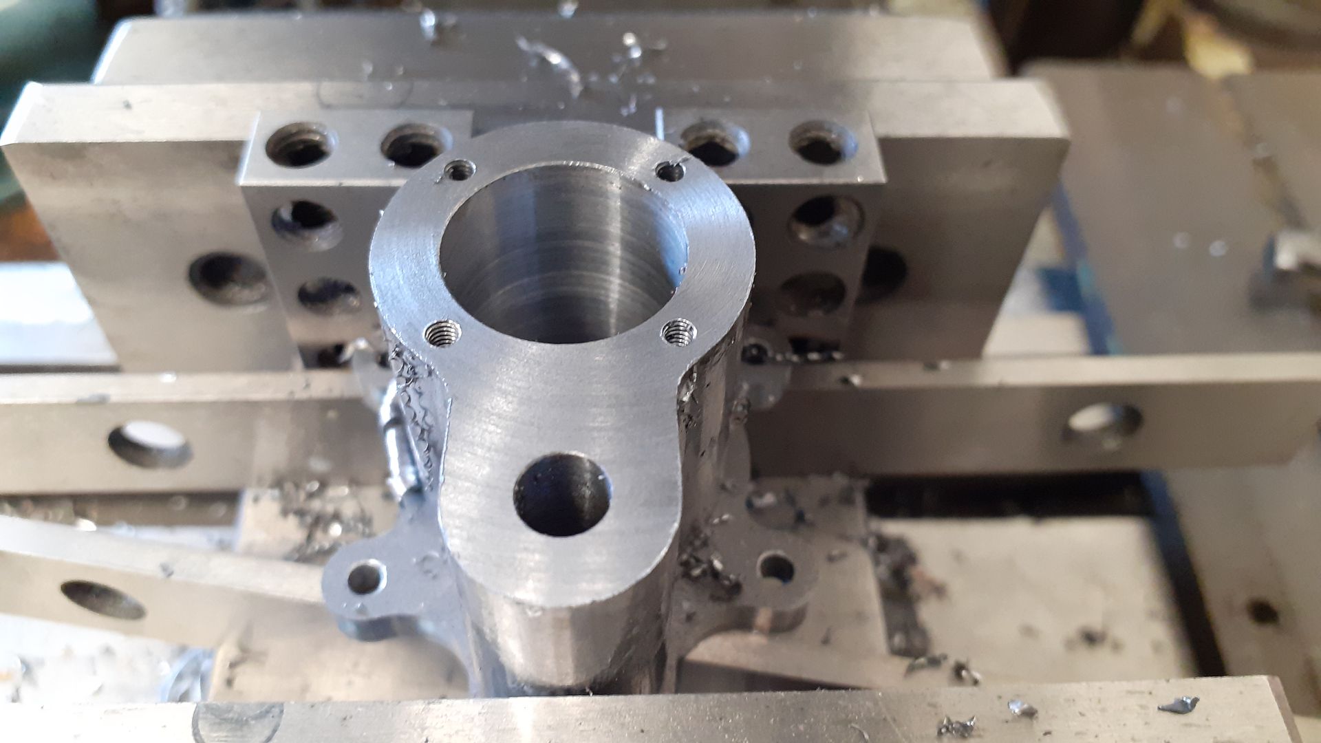
To make sure the cylinder cover holes were lined up correctly I screwed the cylinder to it's entablature and with a couple of 10-20-40 blocks between that and the fixed vice jaw was able to hold it true, locate bore and then drill and tap the four M2.5 holes and later the two M1.6 holes to retain the valve cover plate.

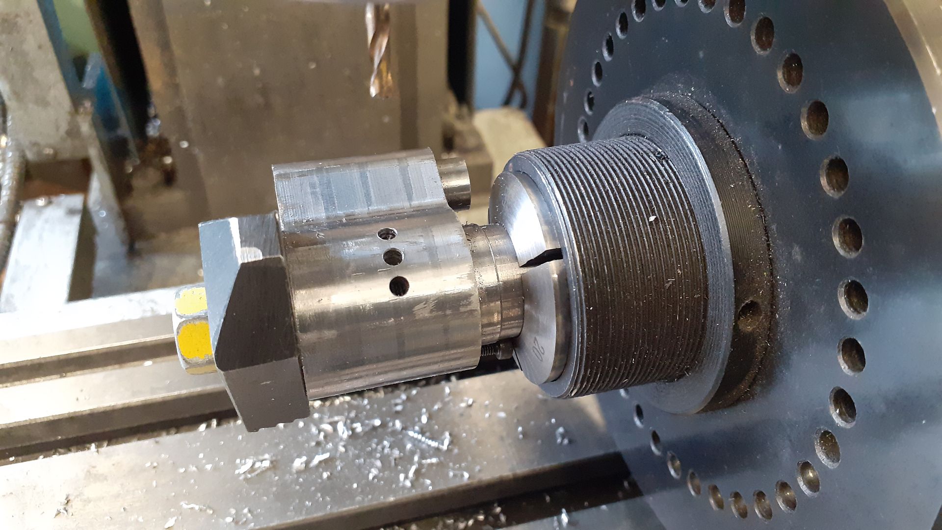
An existing mandrel was quickly altered so the cylinder could be held horizontally in the 5C indexer firstly to drill the inlet passage and then the three exhaust holes each side which are at 20deg spacings.

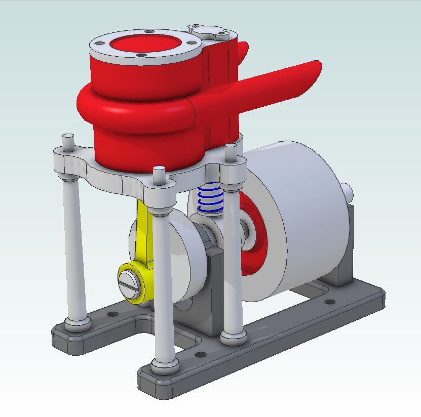
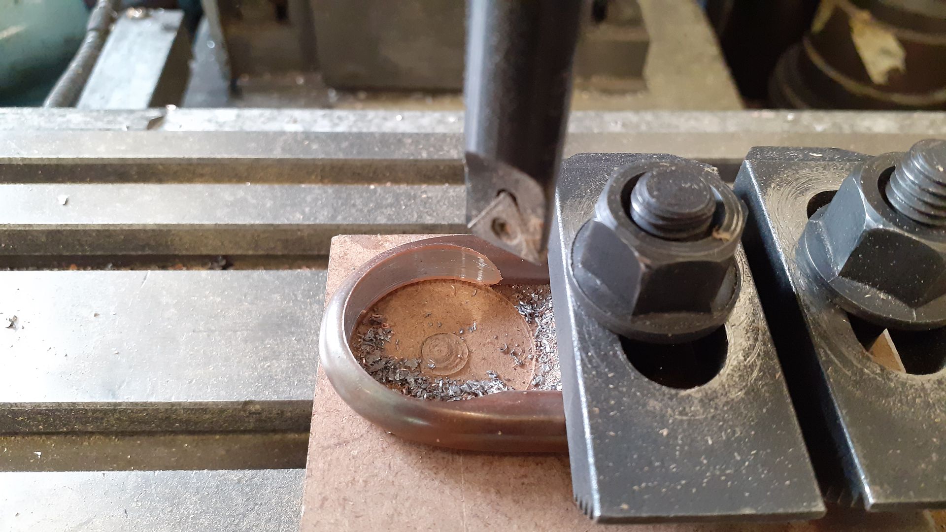
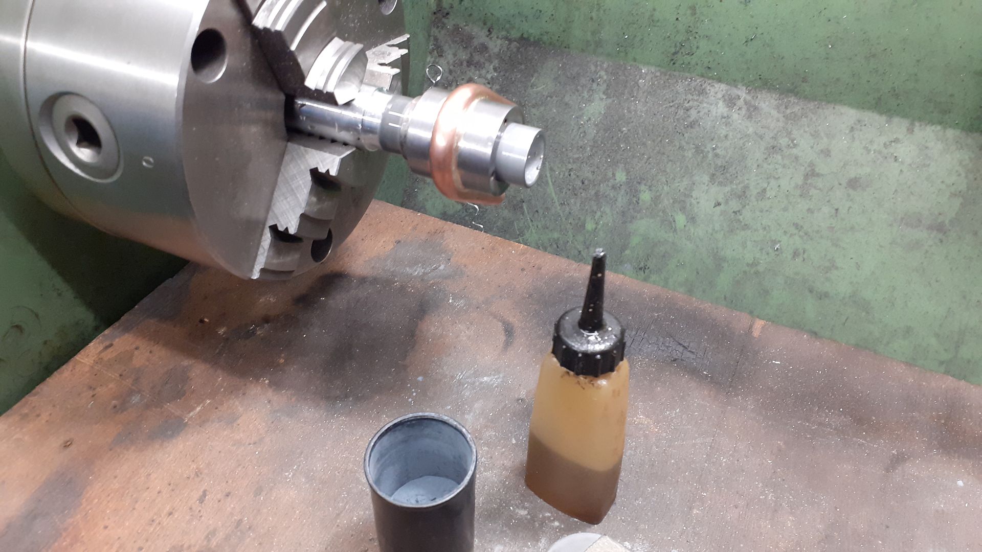
A suitable former was turned from delrin, the 8mm copper tube filled with lead and then bent around the former. I then clamped the "U" shape to a bit of MDF and used the boring head to cut the circular profile so it would slide over the cylinder.

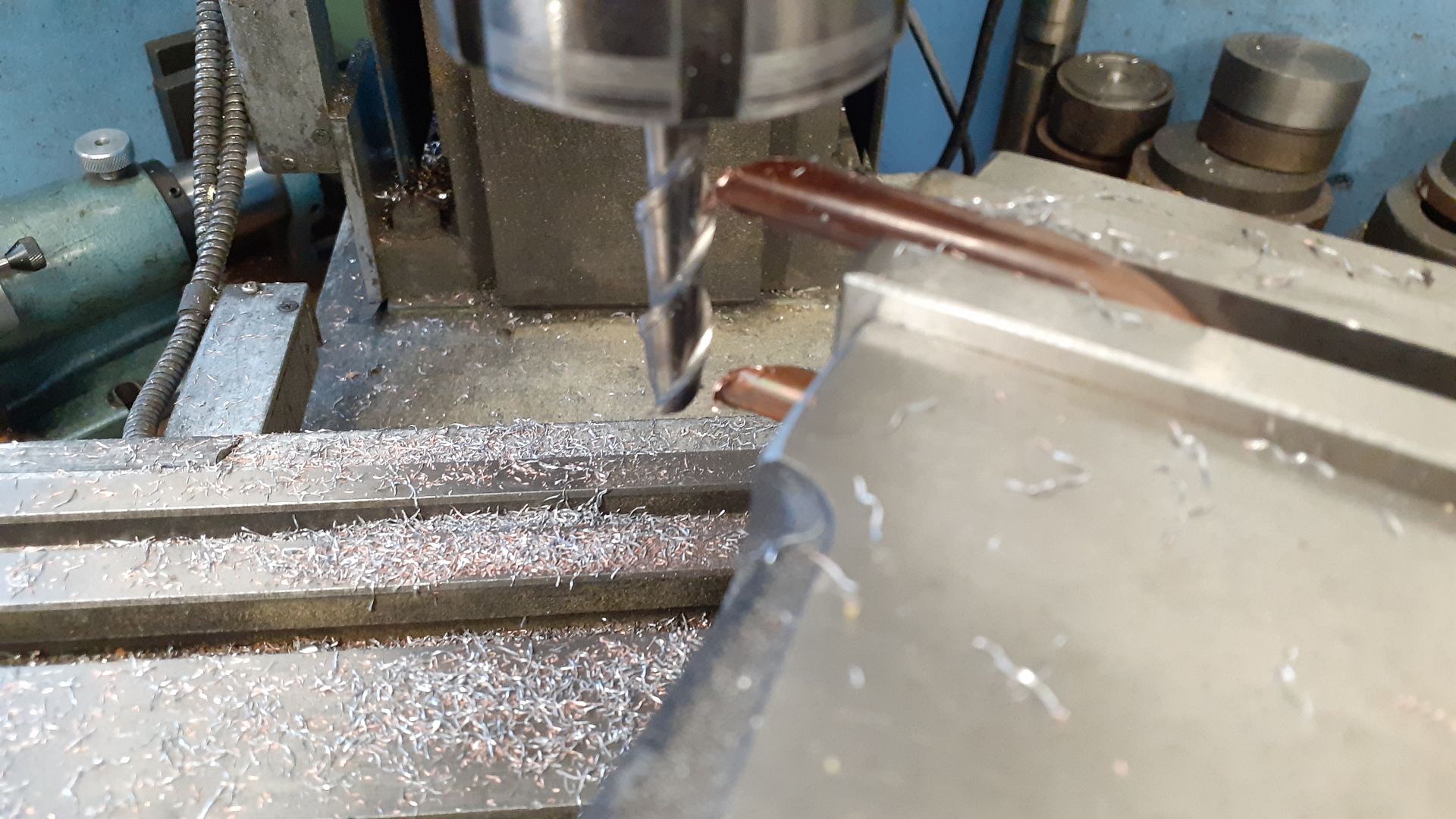
Next the vice was swung round to a pleasing angle and using a long series milling cutter for non-ferrous material both ends were milled to the angle. After this the lead was melted out and the exhaust soldered to the cylinder, I had intended to have the slash cut facing upwards but changed the way I held things for soldering but forgot to turn the pipe up the other way. Still it saved having to paint the inside of the exhaust as it is now just in dark shadow.

After cleaning up the outside the last thing to do was lap the cylinder on a make shift lap turned from a scrap length of thick wall aluminium tube.

duncan webster 1.


